1
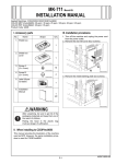
7. Install the cover (six screw B’s furnished with the
kit).
10. Remove the metal blanking plate (four screws).
A02EIXC067DA
4037IXC082DC
11. Mount the plate spring at four positions as illustrated (three screw C’s each, furnished with the
kit).
8. Set the modular cover to the modular jack (TEL).
4037IXC296DA
A02EIXC068DA
9. Remove the shield box cover (four screws).
12. Mount the Fax multi line unit to the rear side of
the machine.
(1) Insert the claw (one position) on the Fax multi
line unit to the mounting hole on the machine.
(2) Attach the connector on the PCI expansion
board (2nd) with the connector on the PCI
expansion board.
(3) Fix the Fax multi line unit to the machine (six
screw B’s furnished with the kit).
A0DCIXC007DA
A02EIXC069DB
E-3