1
6HUYLFH0DQXDO
02'(/
*$1$*95*$*$*95
*$1$*95*$*$*95
5HIULJHUDQW5$
7DEOHRI&RQWHQWV
Content
6XPPDU\DQGFHDWXUHV
6DIHW\3UHFDXWLRQV
6SHFL¿FDWLRQ
8QLW6SHFL¿FDWLRQ
2SHUDWLRQ&KDUDFWHULVWLF&XUYH
&DSDFLW\9DULDWLRQ5DWLR$FFRUGLQJWR7HPSHUDWXUH
2SHUDWLRQ'DWa
1RLVHFULWHULDFXUYHWDEOHVIRUERWKPRGHOV
&RQVWUXFWLRQ9LHZV
,QGRRU8QLW
2XWGRRU8QLW
5HIULJHUDQW6\VWHP'LDJUDP
.
.
6FKHPDWLF'LDJUDP
(OHFWULFDO'DWa
(OHFWULFDOZLULQJ
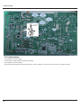
3ULQWHG&LUFXLW%RDUG
)XQFWLRQDQG&RQWURO
5HPRWH&RQWUROOHU'HVFULSWLRQ
&KDQJLQJEDWWHULHVDQGQRWLFHV
8QLWLQGLFDWLRQVHFWLRQ
8QLW212))EXWWRQ
'HVFULSWLRQRI(DFK&RQWURO2SHUDWLRQ
7DEOHRI&RQWHQWV
,QVWDOODWLRQ0DQXDO
7RROV5HTXLUHGIRU,QVWDOODWLRQ
QRWVXSSOLHG
,QVWDOODWLRQ3RVLWLRQ6HOHFWLRQ
,QVWDOODWLRQRI,QGRRU8QLW
,QVWDOODWLRQRI2XWGRRU8QLW
7HVW2SHUDWLRQ
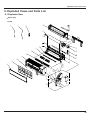
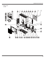
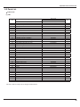
([SORGHG9LHZVDQG3DUWV/LVW
([SORGHG9LHZ
3DUWV/LVW
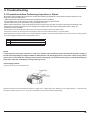
7URXEOHVKRRWLQJ
3UHFDXWLRQVEHIRUH3HUIRUPLQJ,QVSHFWLRQRU5HSDLU
&RQ¿UPDWLRQ
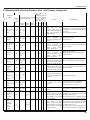
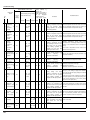
)ODVKLQJ/('RI,QGRRU2XWGRRU8QLWDQG3ULPDU\-XGJHPHQW
+RZWR&KHFNVLPSO\WKHPDLQSDUW
ZD\ZD\9DOYH$SSHDUDQFH
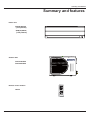
6XPPDU\DQGIHDWXUHV
6XPPDU\DQGIHDWXUHV
,QGRRU8QLW
*$1$*95
FROGSODVPD
*$1$*95
FROGSODVPD
212))
2XWGRRU8QLW
*$*$*95
*$*$*95
5HPRWHFRQWUROZLQGRZ
)$1 $872
23(5
$,5 +($/7+ ;)$1
+80,',7<
),/7(5
785%2
+285
212))
<%)
212))
02'(
)$1
;)$1
7(03
7,0(5
785%2
6/((3
/,*+7
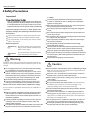
6DIHW\3UHFDXWLRQV
2.Safety Precautions
Important!
or rubbish.
The unit should be installed according to the instructions
This air conditioning system meets strict safety and
operating standards. As for the installer or service person,
in order to minimize the risk of damage from earthquake,
typhoon or strong wind.
it is an important part of your job to install or service the
system and then the unit can operate safely and efficiently.
When the refrigerant touches the fire etc., it was decomposed
and poisonous gas is will be generated.
To prevent injury to the user or other people and
property damage, the following instructions must
Use only the specified refrigerant to charge the refrigerant
circuit.
be followed.
Do not mix it with any other refrigerant and do not allow air to
remain in the circuit.
Follow each installation or repair step exactly as shown.
Observe all local, state, and national electrical codes.
Pay close attention to all warning and caution notices
given in this manual.
About the pictures:
Warning
Erroneous handing gives a high possibility to induce serious results such as
death or heavy injury.
Caution
Erroneous handing may induce serious
injury depending on the situation.
Warning
All electric work must be performed by licensed technician according to local regulations and the instructions given in this
manual.
After completing installation work, make sure that refrigerant gas has not leaked.
The limit density can not be exceeded even if the refrigerant leaks by any chance.
Turn the power off at the main power box (mains) before opening the unit to check or repair electrical parts and wiring.
Keep your fingers and clothes away from any moving parts.
Clean up the site after you've finished, remember to check that
no metal scraps or bits of wiring have been left inside the unit
being serviced.
The unit must be properly earth connected.
Caution
Do not supply power to the unit until all wiring and tubing
Never install the unit at the place where a combustible gas might
are completed or reconnected and checked.
Highly dangerous electrical voltages are used in this
leak. The gas may ignite or explode when the gas leaks and
collects in surround of the unit.
system. Carefully refer to the wiring diagram and these
instructions when wiring. Improper connections and inad-
When the unit is installed at telecommunication centers or
hospitals, take a proper provision against noise.
equate grounding can cause accidental injury or death.
Ground the unit by following local electrical codes.
When installing the unit at a watery place, provide an electric
leak breaker.
Connect all wires tightly. Loose wires may cause overheating at connection points and a possible fire hazard.
Do not wash the unit with water.
Be very careful about unit transportation. The unit should not
There is risk of fire, electric shock, explosion or injury.
Ask your dealer or specialized subcontractor for installation or
repair work.
Make sure that the ceiling/wall is strong enough to hold the
unit’s weight. The outdoor unit should be installed in a
location where air and noise emitted by the unit will not
disturb the neighbors.
Properly insulate any tubing run inside a room to prevent
"sweating" that can cause dripping and the water may
damage walls and floors.
The outdoor unit must be installed on stable, level surface and
the place where there is no accumulation of snow, leaves
Air enclosed in the circuit can cause high pressure and result
in a rupture and other hazards.
be carried by only one person if it is more than 20kg. It may
cause the damage of the unit and personnel injury.
Do not touch the heat exchanger fins with your hands, otherwise
your hands may be hurt.
Do not touch the compressor or refrigerant piping without
wearing glove on your hands. Touching directly such part can
cause a burn or frostbite as it becomes high or low temperature
according to the refrigerant state.
Do not operate the air conditioner without the air filter set
place. Dust may accumulate and a failure may be incurred.
At emergency status(if you smell something burning), stop
the operation and turn off the power immediately.
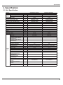
6SHFL¿FDWLRQV
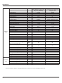
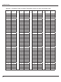
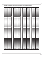
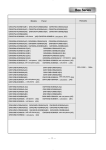
6SHFL¿FDWLRQ
8QLW6SHFL¿FDWLRQ
Model
Product Code
Power Rated Voltage
Rated Frequency
Supply Phases
Power Supply Mode
Cooling Capacity (Min~Max)
Heating Capacity (Min~Max)
Cooling Power Input (Min~Max)
Heating Power Input (Min~Max)
Cooling Power Current
Heating Power Current
Rated Input
Rated Current
Air Flow Volume(SH/H/M/L/SL)
Dehumidifying Volume
EER
COP
SEER
HSPF
Application Area
Model of indoor unit
Fan Type
Diameter Length(DXL)
Fan Motor Cooling Speed
(SH/H/M/L/SL)
Fan Motor Heating Speed
(SH/H/M/L/SL)
Output of Fan Motor
Fan Motor RLA
Fan Motor Capacitor
Input of Heater
Evaporator Form
Pipe Diameter
Row-fin Gap
Indoor Coil Length (LXDXW)
Swing Motor Model
Unit
Output of Swing Motor
Fuse
Sound Pressure Level
(SH/H/M/L/SL)
Sound Power Level
(SH/H/M/L/SL)
Dimension (WXHXD)
Dimension of Carton Box
(L/W/H)
Dimension of Package
(L/W/H)
Net Weight
Gross Weight
ǂ
ǂ
V~
Hz
ǂ
ǂ
W
W
W
W
A
A
W
A
m3/h
L/h
W/W
W/W
W/W
W/W
m2
G
ǂ
mm
GAN/GAG-A180GVR
CB14600360
220-240
50
1
Indoor
5300(1050~6500)
5800(1000~7100)
1600(360~2500)
1600(350~2600)
7.42
7.42
2600
11.60
800/680/560/460
1.8
3.31
3.62
23-34
GAN A180GVR
Cross-flow
ĭ98X650
r/min
1350/1100/950/800/-
1350/1150/1000/850/-
r/min
1400/1200/1050/900/-
1350/1150/1000/900/-
W
A
ȝF
W
ǂ
mm
mm
mm
ǂ
W
A
20
0.31
1.5
Aluminum Fin-copper Tube
ĭ7
2-1.4
657X25.4X304.8
MP28VB
2.0
PCB 3.15A
35
0.31
2.5
Aluminum Fin-copper Tube
ĭ7
2-1.5
765X342.9X25.4
MP35XX
2.5
PCB 3.15A
dB (A)
46/40/37/32/-
48/44/39/34/-
dB (A)
56/50/47/42/-
58/54/49/44/-
mm
865X305X215
1008X319X221
mm
945X380X295
1073X395X313
mm
948X383X310
1076X398X328
kg
kg
12
16
15
20
GAN/GAG-A240GVR
CB14600370
220-240
50
1
Indoor
6450(1400~7000)
6700(1200~8000)
2000(350~2600)
1850(350~2700)
8.87
8.21
2700
11.98
1000/800/700/550/2
3.22
3.62
27-42
GAN A240GVR
Cross-flow
ĭ98X765
Specifications
Outdoor
Unit
Connection
Pipe
Model of Outdoor Unit
ǂA
Compressor Manufacturer/Trademark
ǂ
Compressor Model
Compressor Oil
Compressor Type
L.R.A.
Compressor RLA
Compressor Power Input
Overload Protector
Throttling Method
Operation temp
Ambient temp (cooling)
Ambient temp (heating)
Condenser Form
Pipe Diameter
Rows-fin Gap
Coil Length (LXDXW)
Fan Motor Speed
Output of Fan Motor
Fan Motor RLA
Fan Motor Capacitor
Air Flow Volume of Outdoor Unit
Fan Type
Fan Diameter
Defrosting Method
Climate Type
Isolation
Moisture Protection
Permissible Excessive Operating Pressure for the Discharge Side
Permissible Excessive Operating Pressure for the Suction Side
Sound Pressure Level (H/M/L)
Sound Power Level (H/M/L)
Dimension (WXHXD)
Dimension of Carton Box (L/W/H)
Dimension of Package (L/W/H)
Net Weight
Gross Weight
Refrigerant
Refrigerant Charge
Length
Gas Additional Charge
Outer Diameter Liquid Pipe
Outer Diameter Gas Pipe
Max Distance Height
Max Distance Length
ǂ
ǂ
ǂ
A
A
W
ǂ
ǂ
ć
ć
ć
ǂ
mm
mm
mm
rpm
W
A
ȝF
m3/h
ǂ
mm
ǂ
ǂ
ǂ
ǂ
GAG-A180GVR
China Resources (Shenyang)
Sanyo CO.,LTD/Sanyo
C-6RZ146H1A
FV50S
Rotary
41
8.40
1640
1NT11L-3979
Capillary
16~30
10~48
-15~24
Aluminum Fin-copper Tube
ĭ7
2-1.4
853X660X38.1
690
60
0.58
3.5
3200
Axial-flow
ĭ520
Auto defrost
T1
I
IP24
GAG-A240GVR
China Resources (Shenyang)
Sanyo CO.,LTD
C-6RZ146H1A
FV50S
Rotary
41
8.4
1640
1NT11L-3979
Electron eXpansion valve
16~30
10~48
-15~24
Aluminum Fin-copper Tube
ĭ9.52
2-1.4
847X660X44
690
60
0.58
3.5
3200
Axial-flow
ĭ520
Auto defrost
T1
I
IP24
MPa
3.8
3.8
MPa
1.2
1.2
dB (A)
dB (A)
mm
mm
mm
kg
kg
ǂ
kg
m
g/m
mm
mm
m
m
56/-/66/-/955X700X396
1026X455X735
1029X458X750
52
57
R410A
1.16
5
20
ĭ6
ĭ12
10
25
56/-/66/-/955X700X396
1026X455X735
1029X458X750
55
60
R410A
1.7
5
20
ĭ6
ĭ12
10
25
The above data is subject to change without notice. Please refer to the nameplate of the unit.
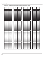
6SHFL¿FDWLRQV
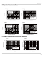
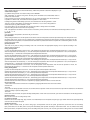
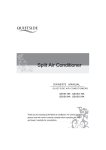
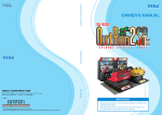
2SHUDWLRQ&KDUDFWHULVWLF&XUYH
.
<Cooling>
<Heating>
11
Current (A)
8
9
8
7
6
230V
5
4
3
7
230V
6
5
240V
4
3
240V
2
220V
10
Current (A)
9
11
220V
• Conditions
Indoor : DB27˚C/WB19˚C
Outdoor : DB35˚C/WB24˚C
Indoor air flow : High
Pipe length : 5m
10
• Conditions
Indoor : DB20˚C/WB15˚C
Outdoor : DB7˚C/WB6˚C
Indoor air flow : High
Pipe length : 5m
2
1
1
0
0
0
10
20
30
40
50
60
80
70
90
0
10 20 30 40 50 60 70 80 90 100 110 120
Compressor speed (rps)
Compressor speed (rps)
.
<Cooling>
<Heating>
11
11
• Conditions
Indoor : DB27˚C/WB19˚C
Outdoor : DB35˚C/WB24˚C
Indoor air flow : High
Pipe length : 5m
9
Current (A)
8
220V
10
220V
9
8
Current (A)
10
7
6
230V
5
4
7
230V
6
5
240V
4
3
3
240V
2
• Conditions
Indoor : DB20˚C/WB15˚C
Outdoor : DB7˚C/WB6˚C
Indoor air flow : High
Pipe length : 5m
2
1
1
0
0
0
10
20
30
40
50
60
70
80
90
0
10 20 30 40 50 60 70 80 90 100 110 120
Compressor speed (rps)
Compressor speed (rps)
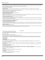
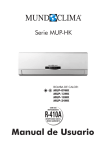
&DSDFLW\9DULDWLRQ5DWLR$FFRUGLQJWR7HPSHUDWXUH
<Cooling>
<Heating>
105
110
100
100
Capacity ratio (%)
Capacity ratio (%)
95
90
85
80
75
70
• Conditions
Indoor : DB27˚C/WB19˚C
Indoor air flow : High
Pipe length : 5m
65
60
55
50
32
33
34
35
36
37
38
39
40
Outdoor temp. (˚C)
41
42
90
80
70
60
• Conditions
Indoor : DB20˚C/WB15˚C
Indoor air flow : High
Pipe length : 5m
50
43
40
–15
–10
–5
0
5
7
10
Outdoor temp. (˚C)
6SHFL¿FDWLRQV
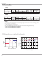
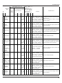
2SHUDWLRQ'DWa
Cooling
Temperature condition
(°C)
Indoor
Outdoor
27/19
35/-
Model name
18K
24K
Standard
pressure
P (MPa)
0.9 to 1.1
0.8 to 1.0
Heat exchanger pipe
temp.
T1 (°C)
T2 (°C)
12 to 14
70 to 40
10 to 12
72 to 40
Standard
pressure
P (MPa)
2.2 to 2.4
2.5 to 2.7
Heat exchanger pipe
temp.
T1 (°C)
T2 (°C)
70 to 35
2 to 4
70 to 35
0 to 3
Indoor fan Outdoor fan
mode
mode
Super High
Super High
Compressor
revolution (rps)
High
High
72
83
Heating
Temperature condition
(°C)
Indoor
Outdoor
20/–
7/6
Model name
18K
24K
Indoor fan Outdoor fan
mode
mode
Super High
Super High
Compressor
revolution (rps)
High
High
66
75
NOTES :
(1) Measure surface temperature of heat exchanger pipe around center of heat exchanger path U
bent. (Thermistor thermometer)
(2) Connecting piping condition : 5 m
(3) P: pressure of air pipe connected to the indoor and outdoor units (gas valve side)
T1: Inlet and outlet temperature for evaporator
T2: Inlet and outlet temperature for condenser
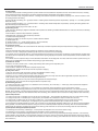
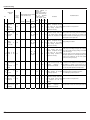
1RLVHFULWHULDFXUYHWDEOHVIRUERWKPRGHOV
Indoor side noise when blowing
54
Heating
50
52
24K
48
40
18K
Noise dB(A)
Noise/dB(A)
50
Cooling
46
44
42
30
Low
Middle
High
40
Indoor fan motor rotating speed
20
30
40
50
60
Compressor frequency(Hz)
70
80
90
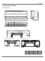
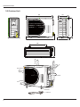
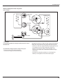
&RQVWUXFWLRQYLHZV
&RQVWUXFWLRQ9LHZV
,QGRRU8QLW
+
ON/OFF
W
'
2YHUPP
2YHU
PP
2YHU
PP
.:DOO0RXQWLQJ)UDPH
.:DOO0RXQWLQJ)UDPH
865
540
175
1008
685
130
150
193
319
298
φ55
φ55
φ55
φ55
40
40
50
50
100
124
0RGHO
.
.
:PP
+PP
'PP
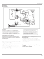
&RQVWUXFWLRQYLHZV
2XWGRRU8QLW
2YHUFP
P
F
HU
Y
2
2YHUFP
2YHUFP
FP
2YHU
%ROW
1XW
:UHQFK
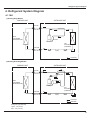
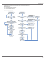
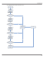
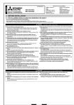
5HIULJHUDQW6\VWHP'LDJUDP
5HIULJHUDQW6\VWHP'LDJUDP
.
&RROLQJ2QO\0RGHOV
INDOOR UNIT
OUTDOOR UNIT
GAS SIDE
3-WAY VALVE
Muffler
Discharge
HEAT
EXCHANGE
(EVAPORATOR)
Suction
Accumlator
COMPRESSOR
HEAT
EXCHANGE
(CONDENSER)
LIQUID SIDE
2-WAY VALVE
Strainer
Capillary
Strainer
COOLING
&RROLQJ+HDWLQJ0RGHOV
INDOOR UNIT
OUTDOOR UNIT
GAS SIDE
3-WAY VALVE
4-Way valve
Muffler
Discharge
HEAT
EXCHANGE
(EVAPORATOR)
Suction
Accumlator
COMPRESSOR
HEAT
EXCHANGE
(CONDENSER)
LIQUID SIDE
2-WAY VALVE
Strainer
Capillary
Strainer
COOLING
HEATING
5HIULJHUDQWSLSHGLDPHWHU
/LTXLGPP
*DVPP
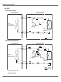
5HIULJHUDQW6\VWHP'LDJUDP
.
&RROLQJ2QO\0RGHOV
INDOOR UNIT
OUTDOOR UNIT
GAS SIDE
3-WAY VALVE
Muffler
Discharge
HEAT
EXCHANGE
(EVAPORATOR)
Suction
Accumlator
COMPRESSOR
HEAT
EXCHANGE
(CONDENSER)
LIQUID SIDE
2-WAY VALVE
Strainer
Expansion valve
Strainer
COOLING
&RROLQJ+HDWLQJ0RGHOV
INDOOR UNIT
OUTDOOR UNIT
GAS SIDE
3-WAY VALVE
4-Way valve
Muffler
Discharge
HEAT
EXCHANGE
(EVAPORATOR)
Suction
Accumlator
COMPRESSOR
HEAT
EXCHANGE
(CONDENSER)
LIQUID SIDE
2-WAY VALVE
Strainer
Expansion valve
Strainer
COOLING
HEATING
5HIULJHUDQWSLSHGLDPHWHU
/LTXLGPP
*DVPP
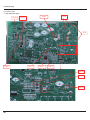
6FKHPDWLF'LDJUDP
6FKHPDWLF'LDJUDP
(OHFWULFDO'DWa
0HDQLQJRIPDUNV
,QGRRU8QLW
6\PERO
%8
<(
5'
<(*1
&RORUV\PERO
%/8(
<(//2:
5('
<(//2:*5((1
6\PERO
%1
%/
%.
&RORUV\PERO
%52:1
%/8(
%/$&.
3527(&7,9(($57+
2XWGRRU8QLW
6\PERO
&
&
6$7
&203
3DUWVQDPH
&%%
&%%
29(5/2$'
&2035(6625
3527(&7,9(($57+
6\PERO
%1
%8
%.
2*
:+
&RORUV\PERO
%52:1
%/8(
%/$&.
25$1*(
:+,7(
6\PERO
:+
<(
5'
<(*1
&RORUV\PERO
:+,7(
<(//2:
5('
<(//2:*5((1
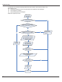
(OHFWULFDOZLULQJ
7KHVHFLUFXLWGLDJUDPVDUHVXEMHFWWRFKDQJHZLWKRXWQRWLFHSOHDVHUHIHUWRWKHRQHVXSSOLHGZLWKWKHXQLW
,QGRRU8QLW
TUBE
TEM. SENSOR
RECEIVER AND
DISPLAY BOARD
AP2
ROOM
TEM. SENSOR
BU
BN
0
RT1
0
RT2
YEGN
ROOM
DISP1
CAP
M2
SWING
MOTOR
N
COM-OUT
AP1
JUMP
SWING-UD
DISP2
AC-L
PGF
NO
L-OUT
COM
HEALTH-L
HEALTH-N
PG
M1
FAN
MOTOR
RD
IONIZER
1BU
2BK
3BN
L
L
4YEGN
L
TERMINAL
BLOCK
BU
N(1)
BK
2
BN
3
YEGN
XT
OUTDOOR UNIT
TUBE
N
PE
EARTH-PLATE
BU PE
EVAPORATOR
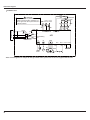
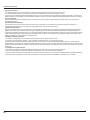
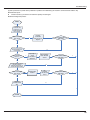
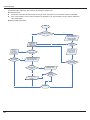
6FKHPDWLF'LDJUDP
2XWGRRU8QLW
4WH
5WH SAT
WARNING
Please don't touch any terminal when the
voltage of terminal P(DC+) and N(DC-) at
AP1 is higher than 30V to prevent the risk
of electrical shock!
R(M,V)
S(W,X)
OUTTUBE OUTROOM EXHAUST
TEM.SENSOR TEM.SENSOR TEM.SENSOR
RT1
0
RT2
0
COMPRESSOR
COMP E 6YEGN
1YE 2BU
RT3
0
C(T,U)
3RD
PE
X1
INDOOR UNIT
WH
YEGN
PE
XT
BU
N(1)
YEGN
BK
2
BK
BN
3
BN
YE
PE
BU
RD
COMP-U COMP-V COMP-W
PE
BU
BK
T-SENSOR
OVC-COMP
N
AP1
COM-INNER(1)
AC-L
TERMINAL BLOCK
4V
OFAN
FA
INDC1
INDC2
OG
WH
4YV
RD
EKV
4-WAY
VALVE
C1
M
YEGN
BN
FAN MOTOR
PE
PFCC1 PFCC2
YE
YE
C2
L
7KHVHFLUFXLWGLDJUDPVDUHVXEMHFWWRFKDQJHZLWKRXWQRWLFHSOHDVHUHIHUWRWKHRQHVXSSOLHGZLWKWKHXQLW
)XQFWLRQDQG&RQWURO
)XQFWLRQDQG&RQWURO
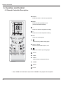
5HPRWH&RQWUROOHU'HVFULSWLRQ
1
ON/OFF
Press this button to start or stop operation.
2
FAN
AUTO
MODE
Press it to select operation mode
OPER
(AUTO/COOL/DRY/FAN/HEAT).
AIR HEALTH X-FAN
HUMIDITY
3
FILTER
-:
Press it to decrease temperature setting.
TURBO
HOUR
ON/OFF
4
+:
Press it to increase temperature setting.
5
FAN
2
1
ON/OFF
Press it to set fan speed.
MODE
6
3
4
Press it to set up &down swing angle.
6
5
7
FAN
HEALTH SAVE
Press it to select health mode on or off.
8
7
8
9
10
X-FAN
12 TURBO13
TEMP
TIMER
SLEEP
LIGHT
Press it to set left & right swing angle.
11
14
9
X-FAN
10
TEMP
11
TIMER
Press it set auto-on timer/auto-off timer.
12
TURBO
13
SLEEP
14
LIGHT
※ Note: X-FAN is the alternative expression of BLOW for the purpose of acceptance.
)XQFWLRQDQG&RQWURO
1
ON/OFF :
Press this button to turn on the unit. Press this button again to turn off the unit.
MODE :
2
Each time you press this button, a mode is selected in a sequence that goes from AUTO, COOL, DRY, FAN,and
HEAT *, as the following:
AUTO
COOL
DRY
FAN
HAET *
*Note:Only for models with heating function.
After energization, AUTO mode is defaulted. In AUTO mode, the set temperature will not be displayed on the
LCD, and the unit will automatically select the suitable operation mode in accordance with the room temperature
to make indoor room comfortable.
3
Press this button to decrease set temperature. Holding it down above 2 seconds rapidly decreases set temperature.
In AUTO mode, set temperature is not adjustable.
4
Press this button to increase set temperature.
. Holding it down above 2 seconds rapidly increases set temperature.
In AUTO mode, set temperature is not adjustable.
5
FAN
This button is used for setting fan speed in the sequence that goes from AUTO,
Auto.
,
, to
, then back to
Auto
Low speed
Medium speed
High speed
:
6
● Press
button to start or stop up & down swing function.The remote controller defaults to simple swing condition.
Press + button and
● blinking 2 seconds.
button at the same time at unit OFF to switch between simple swing and static swing,
In static swing condition, press
button, the swing angle of up & down horizontal louver changes as below:
●
OFF
● If the unit is turned off during swing operation,the louver will stop at present position.
7
HEALTH SAVE:
Press HEALTH part of this button to turn on or off HEALTH function.
Pressing SAVE part of this button,
is displayed and the unit goes into SAVE operation mode. Press SAVE
part of the button again to cancel SAVE function. During SAVE operation, the temperature and fan speed is not
adjustable.
8
:
● Press
button to start or stop left & right swing function.The remote controller defaults to simple swing
condition.
)XQFWLRQDQG&RQWURO
● Press + button and
button at the same time at unit OFF to switch between simple swing and static swing,
blinking 2 seconds.
● In static swing condition, press
button, the swing angle of left & right louver changes as below:
● If the unit is turned off during swing operation,the louver will stop at present position.
9 X-FAN:
Pressing X -FAN button in COOL or DRY mode, the icon "X-FAN" is displayed and the indoor fan will continue
operation for 10 minutes in order to dry the indoor unit even though you have turned off the unit.
After energization, X-FAN OFF is defaulted. X-FAN is not available in AUTO,FAN or HEAT mode.
10 TEMP:
Press this button, could select displaying the indoor setting temperature or indoor ambient temperature.When the
indoor unit firstly power on, it will display the setting temperature, if the temperature's displaying status is changed
from other status to "
", displays the ambient temperature, 5s later or within 5s, it receives other remote control
signal that will return to display the setting temperature. if the users haven't set up the temperature displaying
status,that will display the setting temperature.
11 TIMER:
Press TIMER button at unit ON to set TIMER OFF, HOUR OFF blinking. Press TIMER button at unit OFF to set TIMER
ON, HOUR ON blinking. In this case, pressing + or - button changes time setting.
Holding down either button rapidly changes time setting (time setting range 0.5-24hours). Press TIMER button again to
confirm setting, HOUR ON/OFF stopping blink. If there is not any operation of button within 5 seconds during HOUR
ON/OFF blinking, TIMER setting will be canceled.
12 TURBO:
Press this button to activate / deactivate the Turbo function which enables the unit to reach the preset
temperature in the shortest time. In COOL mode, the unit will blow strong cooling air at super high fan speed.
In HEAT mode, the unit will blow strong heating air at super high fan speed. (This function is not applicable for
some models).
13 SLEEP :
Press this button to go into the SLEEP operation mode. Press it again to cancel SLEEP operation. This function is
available in COOL , HEAT (Only for models with heating function) or DRY mode to maintain the most comfortable
temperature
14 LIGHT:
Press LIGHT button to turn on the display's light and press this button again to turn off the display's light. If the light
is tunrned on ,
is displayed. If the light is tunrned off,
disappears.
4 and 3
About lock:
Press "+ " and "-" buttons simultaneously to lock or unlock the keypad. If the remote controller is locked,
displayed. In this case, pressing any button,
blinks three times.
3 and 2
About switch between fahrenheit and cenrigrade
At unit OFF, press "MODE" and "- " buttons simultaneously to switch between ℃ and ℉.
is
)XQFWLRQDQG&RQWURO
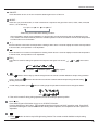
&KDQJLQJBDWWHULHVDQG NRWLFHV
Remove the battery cover plate from the rear of the remote controller. (As shown in the figure)
1. 2 Take out the old batteries.
3. Insert two new AAA1.5V dry batteries and pay attention to the polarity.
4 Reinstall the battery cover plate.
ƾ NOTE:
ƽ When replacing the batteries, do not use old or different batteries,
otherwise, it may cause malfunction.
ƽ If the wireless remote controller will not be used for a long time, please
remove batteries to prevent damage from leaking batteries.
ƽ The operation should be performed in its receiving range.
ƽ It should be kept 1m away from the TV set or stereo sound sets.
ƽ If the wireless remote controller does not operate normally, please take
the batteries out and replace them after 30 seconds. If it still can't operate
properly, replace the batteries.
Sketch map for
changing batteries
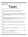
8QLWLQGLFDWLRQSHFWLRQ
:KHQWKHXQLWLVHQHUJL]HGDOOWKHGLVSOD\PDUNVZLOOEHVKRZQDQGRQO\
WKHSRZHU/('OLJKWV
:KHQWKHXQLWLVWXUQHGRQUHPRWHO\WKHSRZHU/('JRHVRXWZKLOHWKH
FXUUHQWVHWWLQJUXQQLQJPRGHLVGLVSOD\HG
'XULQJGHIURVWLQJ³+´LVGLVSOD\HGLQ³GXDO´
,QQRUPDOVLWXDWLRQWKHVHWWLQJWHPSHUDWXUHLVGLVSOD\HGLQ³GXDO´SODFH
:KHQ WKH VLJQDO RI GLVSOD\LQJ LQGRRU WHPSHUDWXUH RU RXWGRRU WHPSHUD
WXUH LV UHFHLYHG IURPWKH FRQWUROOHUWKH FRUUHVSRQGLQJ WHPSHUDWXUH ZLOO EH
VKRZQLQ³GXDO´SODFH,WUHVXPHVGLVSOD\LQJVHWWLQJWHPSHUDWXUHVODWHU
COOL light (blue)
DRY light (green)
RUN light (red)
HEAT light (orange)
ON/OFF
Unit ON/OFF button
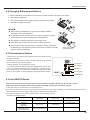
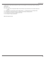
8QLW212)) BXWWRQ
,IWKHUHPRWHFRQWUROlerLVORVWRUEURNHQSOHDVHXVHWKHPDQXDOVZLWFKEXWWRQ$WWKLVWLPHWKHXQLWZLOOUXQDWWKH
$XWRPRGHEXWWKHWHPSHUDWXUHDQGIDQVSHHGFDQQRWEHFKDQJHG7KHRSHUDWLRQZDVVKRZQDVEHORZ
7RRSHQWKHSDQHOWKHPDQXDOVZLWFKLVRQWKHGLVSOD\HUER[
7XUQRQWKHXQLW$fter XQLWis WXUQHGRIISUHVVWKHEXWWRQWKHXQLWZLOOUXQDW$XWRPRGHLPPHGLDWHO\7KHPLFURFRPSXWHUZLOODFFRUGWRWKH
LQGRRUWHPSHUDWXUHWRVHOHFW&RROLQJ+HDWLQJ)DQDQGREWDLQWKHFRPIRUWDEOHHIIHFW
7XUQRIIWKHXQLW$fterXQLW is WXUQHGRQSUHVVWKHEXWWRQWKHXQLWZLOOVWRSZRUNLQJ
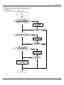
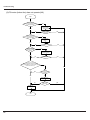
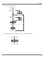
2SHUDWLRQRIDXWRPDWLFEXWWRQV
less than 5s
operation
during stop
start running
operation
during running
stop running
operation during stop
˄communication error˅
(after running, abnormal)
keep 5 ~ 10 s
start compulsory running
keep more than 10s
stop compulsory running
(avoid button lock)
stop running
)XQFWLRQDQG&RQWURO
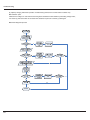
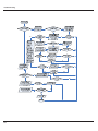
'HVFULSWLRQRI(DFK&RQWURO2SHUDWLRQ
Indoor Unit
Temperature Parameter
ƹ Room setting temperature (Tpreset)
ƹ Room ambient temperature (Tamb.) (temperature sensor :15K, partial pressure resistance:15K)
ƹ Surface temperature of copper pipe for indoor heat exchanger (Tindoor tube) (temperature sensor: 20K, partial pressure resistance: 20K)
1. Basic Functions of System
(1) Cooling Mode
1. In this mode, indoor fan and swing will operate according to the setting status. The temperature setting range is 16~30ć.(Fahrenheit: 61~86̧).
2. When the unit stop operation due to malfunction of outdoor unit or protection, indoor unit will keep original operating status. Malfunction code will be
displayed.
3. When 0(Tpreset-Tamb.), if the indoor unit is operating at high fan speed, the speed of fan will change to medium fan speed; if the indoor unit is
operating at medium or low fan speed, the speed of fan will keep the same; (This condition can only be carried out after the compressor is started up);
There’s no change for super-high fan speed; when (Tamb.-Tpreset)1ć, the fan speed will resume setting fan speed;
(2) Dry Mode
1. In this mode, fan will operate at low fan speed and swing will operate at setting status. The temperature setting range is 16~30ć.(Fahrenheit:
61~86̧).
2. When the unit stop operation due to malfunction of outdoor unit or protection, indoor unit will keep original operating status. Malfunction code will be
displayed.
(3) Fan Mode
1. In this mode, indoor fan will operate at high, medium, low or auto fan speed. Compressor, indoor fan and the four-way valve will all stop operation.
2. In this mode, the temperature setting range is 16~30ć.(Fahrenheit: 61~86̧).
(4) Heating Mode
1. In this mode, the temperature setting range is 16~30ć. (Fahrenheit: 61~86̧).
2. Working condition and process of heating: when the unit is turned on in heating mode, indoor unit enters into anti-cold air condition; when the unit is
tuned off, the unit will enter into the condition of blowing residual heat.
3. Protection function: in heating mode, when the compressor is stopped due to malfunction, indoor fan will operate at the condition of blowing residual
heat.
4. Defrosting control: after receiving the defrosting signal from outdoor unit, the defrosting code H1 will be displayed.
5. Anti-cold function
6. Blowing residual heat function;
a. During heating operation, when the stopping condition for the compressor is reached, the compressor and the outdoor fan motor stop operation. The
upper& down horizontal louver will rotate to the horizontal position L. The indoor fan will be stopped after operating for 60s at setting speed.
b. Due to the blockage of PG motor, horizontal louver will keep the stop position when the unit is turned off. (In other modes) When the unit is stopped
due to other malfunctions, up&down horizontal louver will rotate to horizontal position L. The indoor fan will be stopped after operating for 60s at setting
speed.
c. If the unit is turned off when the compressor is operating in heating mode or auto heating mode, up&down horizontal louver will rotate to horizontal
position L. The indoor fan will be stopped after operating for 60s at setting speed.
(5) Auto Mode
1. When Tamb.26ć, the unit will operate in cooling mode. The implied setting temperature is 25ć. ((Fahrenheit: 77̧).
2. Heat pump type: when Tamb22ć, the unit will operate in heating mode. The implied setting temperature is 20ć. ((Fahrenheit: 68̧).
3. Cooling only unit: when Tamb25ć, the unit will operate in auto mode. The implied setting temperature is 25ć. ((Fahrenheit: 77̧).
4. When 23ćTindoor amb. 25ć, the unit will operate in auto fan mode if the unit is turned on and enters into the auto mode for the fist time. If the
unit is switched to auto mode from other mode, it will keep the previous operation mode (if the unit is switched to auto mode from dry mode, the unit will
operate at auto fan mode).
2. Display Status of Indoor Indicator
(1) Status of Indoor Display Board
1. After energization, all the icons will be displayed and then only the power indicator is bright. When the unit is turned on by remote controller, the
operation indicator will be bright. Meanwhile, the current setting operation mode will be displayed.
2. During defrosting, “dual-8” will display “H”.
3. “Dual-8” displays setting temperature.
¾
Display of Operation Icon and Mode Icon
After energization, all the icons will be displayed for once. In standby status, the operation indicator will be in red. If turn on the unit by remote controller,
the operating indication icon will be bright. Meanwhile, the current setting operation mode will be displayed (mode indicator: cooling indicator, heating
indicator, dry indicator). If turn off the light button, all displays will be turned off.
¾
Temperature display control mode for split type unit
1. When user set the remote controller as the setting temperature display status, the current setting temperature will be displayed on remote
controller.
2. Only when the remote control signal is switched to indoor ambient temperature display status from other display status, controller will display the
indoor ambient temperature for 5s and then turn back to display the setting temperature.
3. When user hasn’t set the temperature displaying status, it will be displayed according to the setting temperature.
(2)Malfunction Display of Indoor Unit
)XQFWLRQDQG&RQWURO
When multiple malfunctions occurred simultaneously, malfunction protection codes will be displayed in cycle.
3.Other Control Target
(1) Up&down swing function: the mode for swing motor is MP28EA
After energization, up & down swing motor will firstly let the horizontal louver anticlockwise rotate to
position 0 to close air outlet.
If swing function has not been set after startup of the unit, up & down horizontal louver will clockwise turn
to position D in HEAT mode, or clockwise turn to level position L in other modes.
If setting swing function while starting up the unit, the horizontal louver will swing between L and D.
There are 7 kinds of swing status of horizontal louver: Positions L, A, B, C and D, swing between L
and D and stop at any position between L and D.
Upon turning off the unit, the horizontal louver will close at position 0. Swing function is available
only when swing function set and indoor fan is operating.
Note: If the position is set between L and B, A and C or B and D by remote controller, the horizontal louver will swing between L and D.
L----A----B----C----D
(2) Buzzer
Upon energization and operation, the buzzer will give out sound.
(3) Auto Button
After pressing this button, the unit will operate in auto mode. Indoor fan will operate at auto fan speed and swing motor will operate. Press
this button again to turn off the unit. The complete unit is energized when pressing the button and the complete unit will enter into fast
testing status. After energization, if it’s detected that the auto button is pressed down and the complete unit is at fast testing status, the fast
testing status will be exited.
(4) Sleep Function
This mode is only valid in cooling and heating mode. The unit will select the appropriate sleeping curve to operate according to the
different setting temperature.
During cooling mode:
(1) When the initial temperature is set as 16~23ć, after starting up the sleep function, the temperature will increase by1ć every one hour.
After the temperature has increased by 3ć, the unit will keep this temperature. When the unit has operated for 7 hours, the temperature
will decrease by 1ć and then the unit will operate at this temperature all the time;
(2) When the initial temperature is set as 24~27ć, after starting up the sleep function, the temperature will increase by1ć every one hour.
After the temperature has increased by 2ć, the unit will keep this temperature. When the unit has operated for 7 hours, the temperature
will decrease by 1ć and then the unit will operate at this temperature all the time;
(3) When the initial temperature is set as 28~29ć, after starting up the sleep function, the temperature will increase by1ć every one hour.
After the temperature has increased by 1ć, the unit will keep this temperature. When the unit has operated for 7 hours, the temperature
will decrease by 1ć and then the unit will operate at this temperature all the time;
(4) When the initial temperature is set as 30ć, the unit will operate at this temperature. After the unit has operate for 7hours, the
temperature will decrease by 1ć and then the unit will operate at this temperature all the time.
During Heating Mode:
(1) When the initial temperature is set at 16ć, the unit will operate at this temperature all the time;
(2)When the initial temperature is set as 17~20ć, after starting up the sleep function, the temperature will decrease by1ć every one hour.
After the temperature is decreased by 1ć, the unit will operate at this temperature;
(3)When the initial temperature is set as 21~27ć, after starting up the sleep function, the temperature will decrease by1ć every one hour.
After the temperature is decreased by 2ć, the unit will operate at this temperature;
(3)When the initial temperature is set as 28~30ć, after starting up the sleep function, the temperature will decrease by1ć every one hour.
After the temperature is decreased by 3ć, the unit will operate at this temperature;
General timer and clock timer functions are compatible by equipping different functions of remote controller.
(5) Timer Function
General timer and clock timer functions are compatible by equipping different functions of remote controller.
General timer:
Timer ON
If timer ON is set during operation of the unit, the unit will continue to operate. If timer ON is set at unit OFF, upon ON time reaches the unit will start to
operate according to previous setting status.
Timer OFF
If timer OFF is set at unit OFF, the system will keep standby status. If timer OFF is set at unit ON, upon OFF time reaches the unit will stop operation.
(6) Blow Function
Blow function can be set in cooling and dry mode.
(7) Indoor Fan Control
Indoor fan can be set at super-high, high, medium or low. Meanwhile, the fan will operate at super-high, high, medium and low fan speed respectively
and it can also set at auto fan speed.
(8) Memory Function
Memory content includes mode, up & down swing, light, set temperature and set fan speed, general timer (clock timer can’t be memorized),
Upon power failure, the unit after power recovery will automatically start operation according to memorized content. The unit, without timer setting
before power failure, will operate according to the last setting after power recovery. The unit, with general timer setting which has not been fulfilled
)XQFWLRQDQG&RQWURO
before power failure, will memorize the time setting and re-calculate the time after power recovery. If there is timer function in the last remote controller
command but setting time has reached, the system will act as timer on/off setting before power failure. After power failure, the system memorizes the
operation states before power failure without timer action. Clock timer can not be memorized.
(9) Locked protection to PG motor
If the indoor fan motor’s rotational speed after startup keeps slow for a continuous period of time, the unit will stop operation and display “H6”.
(10)Turbo Function
This function can be set in cooling or heating mode to quickly cool or heat the room˄Turbo function is not available in auto, dry and fan mode˅. After
pressing the turbo button, indoor fan will operate at super-high fan speed.
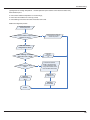
5. Malfunction Detection for Temperature sensor
(1) Indoor ambient temperature sensor:
Malfunction of temperature sensor will be detected at any time;
(2) Indoor tube temperature sensor
Malfunction of temperature sensor won’t be detected during defrosting period. It starts detecting the malfunction of temperature sensor after defrosting
is finished for 5 mins. Malfunction of temperature sensor will be detected at any other time.
(3) Protection of temperature sensor
1. When the temperature sensor is detected short circuit for 30s successively:
The detected temperature by the temperature sensor is too high and the complete unit will stop operation, meanwhile, the protection and malfunction of
temperature sensor will be displayed accordingly.
2. When the temperature sensor is detected open circuit for 30s successively: The unit will stop operation due to protection and the corresponding
malfunction of temperature sensor will be displayed directly.
6. Compulsory operating function of indoor unit
(1) Enter into compulsory operation control
After the unit is energized for 5mins, press the light button on remote controller for 3 times in 3s successively to enter into Freon recovery mode. Fo will
be displayed. When Freon recovery mode operated for 25mins, all loads will operate in cooling mode. (The setting fan speed is high fan speed and the
setting temperature is 16ć)
(2) Exit the compulsory operation control
Freon recovery mode will be exited after receiving any signal from remote controller or button and then the unit will operate at the current setting
command; Freon mode will also be exited after operating for 25mins and then the unit will be turned off.
Outdoor Units
1. Input Parameter Compensation and Calibration
(1) Check the input parameter compensation function
As the instruction feature of split unit, concerning the comfortable, in heating mode, the indoor ambient temperature of compressor stopping time is higher
than preset temperature.
(2) Check effective judgment controls of parameters
Effective judgment function of the outdoor exhaust temperature thermo-bulb
When conditions a and b are satisfied, the outdoor exhaust temperature thermo-bulb is judged not to be connected into place, the mainboard of outer
units will display failure of the outdoor exhaust temperature thermo-bulb (not connected into place), stop the unit for repairing, and resume it by remote
controls of ON/OFF.
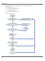
2. Basic Functions
(1) Cooling Mode
1. Conditions and processes of cooling operation:
(1) If the compressor is stop, and [Tpreset – (Tindoor ambient – ¨Tcooling indoor ambient temperature compensation)] 0.5ć, start up the unit for
cooling, and start to cooling operation;
(2) During operations of cooling, if 0ć [Tpreset – (Tindoor ambient –¨Tcooling indoor ambient temperature compensation)] < 2ć, the cooling operation
will be still running;
(3) During operations of cooling, if 2ć [Tpreset – (Tindoor ambient –¨Tcooling indoor ambient temperature compensation)], the cooling operation will
stop after reaching to the temperature point.
2. Temperature setting range
(1) If Toutdoor ambient [Tlow-temperature cooling], the temperature can be set at: 16~30ć (Cooling at room temperature);
(2) If Toutdoor ambient < [Tlow-temperature cooling], the temperature can be set at: 25~30ć (Cooling at low temperature), that is, the minimum setting
temperature for outdoor unit judgment is 25ć.
(2) Dry Mode
1. Conditions and processes of dry operations: Same as the cooling mode;
2. The temperature setting range is: 16~30ć;
(3) Fan Mode
1. The compressor, outdoor fan and four-way valve are switched off;
2. The temperature setting range is: 16~30ć.
)XQFWLRQDQG&RQWURO
(4) Heating Mode
1. Conditions and processes of heating operations: (Tindoor ambient is the actual detection temperature of indoor environment thermo-bulb, ¨Theating
indoor ambient temperature compensation is the indoor ambient temperature compensation during heating operations)
(1) If the compressor is stop, and [(Tindoor ambient –¨Theating indoor ambient temperature compensation) –Tpreset] 0.5ć, start the machine to enter
into heating operations for heating;
(2) During operations of heating, if 0ć [(Tindoor ambient –¨Theating indoor ambient temperature compensation) –Tpreset] < 2ć, the heating operation
will be still running;
(3) During operations of heating, if 2ć [(Tindoor ambient –¨Theating indoor ambient temperature compensation) –Tpreset], the heating operation will
stop after reaching the temperature point.
2. The temperature setting range in this mode is: 16~30ć.
(5) Defrosting Control
1. After the time for defrosting is judged to be satisfied, if the temperature for defrosting is satisfied after detections for continuous 3minutes, the defrosting
operation will start.
2. Start to defrost: Compressor stops and starts up 55S later;
3. Defrosting finish: Compressor stops and starts up 55S later;
4. Conditions of finishing defrosting
The defrosting operation can exit when any of the conditions below is satisfied:
(1) Toutdoor pipe 12ć;
(2) Toutdoor ambient⧞-5ć, and the Toutdoor pipe 6ć last more than 80S;
(3) The continuous running time of defrosting reaches to 8min.
(6) Compressor Control
1. The frequency of compressor will be controlled with the relationship of ambient temperature and preset temperature and changing speed of ambient
temperature;
2. Start the compressor after starting cooling, heating, dry operations, and the outdoor fan start for 5s;
3. When the unit is off, in safety stops and switching to fan mode, the compressor will stop immediately;
4. In all modes: once the compressor starts up, it will not be allowed to stop until having run for the [tmin. Compressor running time] (Note: including cases
of shutdown when the temperature point is reached; except the cases requiring stopping the compressor such as fault protection, remote shutdown, mode
switching etc.);
5. In all modes: once the compressor stops, it will be allowed be restart after 3-minute delay (Note: The indoor units have a function of power memory, the
machine can be restarted after remote shutdown and powering up again without delay).
(7) Outdoor Fan Control
1. When the unit is off by remote controlʙin safety stops and stop after reaching to the temperature point.
2. In fan mode: The outdoor fan stops;
3. Start to defrost: Outdoor fan will stop after compressor stops for 50S;
4. Defrosting finish: Outdoor fan will start up when the compressor is stopping.
(8) 4-way valve control
1. The 4-way valve control under the modes of Cooling, dehumidification and fan: closing;
2. When the unit is on in heating mode, the 4-way valve is energized;
3. When the unit is on in heating mode and heating mode shift to other modes, the 4-way valve will be de-energized after compressor stops for 2min;
4. After protection stops, the 4-way valve will be de-energized after 4min;
5. Start to defrost: The power of 4-way valve will be de-energized after the compressor stops;
6. Defrosting finish: The 4-way valve will be energized after the compressor stops.
(9) Anti-freezing protection
1. In cooling and dry mode, if Tindoor pipe˘0 is detected for 3min continuously, the unit will stop; if ˘Tindoor pipe, and compressor has stopped for
3min, the unit will resume running;
2. In cooling and dry mode, if Tindoor pipe˘6, running frequency of compressor will be decreased or stop to increase will be occurred;
3. If the unit stops as anti-freezing protection for 6 times, it can not resume running automatically and display malfunction, it can resume by pressing
ON/OFF. During operation, if the time exceeds compressor running time, the time of anti-freezing protection stop will zero clearing. When the unit is off/
fan/ heating mode, the malfunction and malfunction times will zero clearing. (If the malfunction can not resume, the shifting mode can clear malfunction.)
(10) Overload protection
1. In cooling and dry mode: if Toutdoor pipe, the unit will stop; if Toutdoor pipe˘, and compressor has stopped for 3min, the unit will resume running;
2. In cooling and dry mode: if Toutdoor pipe, running frequency of compressor will be decreased or stop to increase will be occurred;
3. In heating mode: if Tindoor pipe, the unit will stop; if Tindoor pipe˘, and compressor has stopped for 3min, the unit will resume running;
4. In cooling and dry mode: if Tindoor pipe, running frequency of compressor will be decreased or stop to increase will be occurred;
5. If the unit stops as overload protection for 6 times, it can not resume running automatically and display malfunction, it can resume by pressing ON/OFF.
During operation, if the time exceeds compressor running time, the time of overload protection stop will zero clearing. When the unit is off/ fan/ shifts to
heating mode, the malfunction and malfunction times will zero clearing. (If the malfunction can not resume, the shifting mode can clear malfunction.)
(11) Compressor discharge temperature protection
1. If Tdischarge, the unit will stop; if Tdischarge˘, and compressor has stopped for 3min, the unit will resume running;
2. If Tdischarge, running frequency of compressor will be decreased or stop to increase will be occurred;
3. If the unit stops as compressor discharge temperature for 6 times, it can not resume running automatically and display malfunction, it can resume by
pressing ON/OFF. During operation, if the time exceeds compressor running time, the time of compressor discharge temperature stop will zero clearing.
When the unit is off/ shifts to fan mode, the malfunction and malfunction times will zero clearing. (If the malfunction can not resume, the shifting mode can
clear malfunction.)
)XQFWLRQDQG&RQWURO
(12) Current protection
1. If 12AI alternating-current, running frequency of compressor will be decreased or stop to increase will be occurred;
2. If 17AI alternating-current, the unit will stop; and compressor has stopped for 3min, the unit will resume running;
3. If the unit stops as compressor discharge temperature for 6 times, it can not resume running automatically and display malfunction, it can resume by
pressing ON/OFF. During operation, if the time exceeds compressor running time, the time of compressor discharge temperature stop will zero clearing.
(13) Drop off voltage
During compressor operation, the system will stop and malfunction of drop off voltage if voltage downward fluctuates rapidly, and it will re-start up
automatically 3min later.
(14) Communication malfunction
If the unit does not receive correct signal from indoor unit for 3min continuously, the unit will stop as communication malfunction protection; if
communication malfunction resume and compressor has stopped for 3min, the unit will resume running.
(15) IPM module protection
When the compressor starts, if there is overcurrent or control voltage low for IPM module as some abnormal results, IPM will detect module protection
signal as the unit is on. Once the module protective signal is detected, stop the unit with module protection immediately. If the module protection is
resumed and compressor has stopped for 3min, the unit will be allowed to operate. If the module protection continuously occurs for three times, it should
not be resumed automatically, and you should press the ON/OFF button to resume. If the running time of compressor exceeds the [t Protection times
clearing of module], the module protection is cleared to recount.
(16) Module overheating protection
1. If Tmodule, running frequency of compressor will be decreased or stop to increase will be occurred;
2. If Tmodule, the unit will stop; if Tmodule˘, and compressor has stopped for 3min, the unit will resume running;
3. If the unit stops as module overheating protection for 6 times, it can not resume running automatically and display malfunction, it can resume by
pressing ON/OFF. During operation, if the time exceeds compressor running time, the time of module overheating protection stop will zero clearing. When
the unit is off/ shifts to fan mode, the malfunction and malfunction times will zero clearing. (If the malfunction can not resume, the shifting mode can clear
malfunction.)
(17) Compressor overload protection
1. If the switch of compressor overload de-energized is detected for 3S continuously, the system will stop as protection;
2. If the overload protection is resumed and compressor has stopped for 3min, the unit will be allowed to operate.
3. If the unit stops as compressor overload protection occurred for 3 times continuously, it can not resume running automatically and display malfunction,
it can resume by pressing ON/OFF; and the times of compressor overload protection will be cleared after the compressor has run for 30min.
,QVWDOODWLRQ0DQXDO
,QVWDOODWLRQ0DQXDO
,PSRUWDQW1RWLFHV
7KHXQLWLQVWDOODWLRQZRUNPXVWEHGRQHE\TXDOL¿HG
SHUVRQQHODFFRUGLQJWRWKHORFDOUXOHVDQGWKLV
PDQXDO
% H I R U H L Q V W D O O L Q J S O H D V H F R Q W D F W Z L W K O R F D O
DXWKRUL]HGPDLQWHQDQFHFHQWHULIXQLWLVQRWLQVWDOOHG
E\WKHDXWKRUL]HGPDLQWHQDQFHFHQWHUWKHPDOIXQFWLRQ
PD\QRWVROYHGGXHWRGLVFRPPRGLRXVFRQWDFWV
:KHQ UHPRYLQJ WKH XQLW WR WKH RWKHU SODFH SOHDVH
¿UVWO\FRQWDFWZLWKWKHDXWKRUL]HG0DLQWHQDQFH
&HQWHULQWKHORFDODUHD
%DVLF5HTXLUHPHQWV)RU,QVWDOODWLRQ
3RVLWLRQ
,QVWDOO LQ WKH IROORZLQJ SODFH PD\ FDXVH PDOIXQFWLRQ ,I LW LV
XQDYRLGDEOHFRQWDFWZLWKVHUYLFHFHQWHUSOHDVH
3ODFH ZKHUH VWURQJ KHDW VRXUFHV YDSRUV IODPPDEOH JDV RU
YRODWLOHREMHFWDUHHPLWWHG
3ODFH ZKHUH KLJKIUHTXHQF\ ZDYHV DUH JHQHUDWHG E\ UDGLR
HTXLSPHQWZHOGHUVDQGPHGLFDOHTXLSPHQW
3ODFHZKHUHDORWRIVDOLQLWLHVVXFKDVFRDVWH[LVWV
3ODFHZKHUHWKHRLOPDFKLQHRLOLVFRQWDLQHGLQWKHDLU
3ODFHZKHUHDVXOIDWHGJDVVXFKDVWKHKRWVSULQJ]RQHVLVJHQ
HUDWHG
2WKHUSODFHZLWKVSHFLDOFLUFXPVWDQFH
7RROV5HTXLUHGIRU,QVWDOODWLRQ
QRWVXSSOLHG
*DXJHPDQLIROG
(OHFWURQLFEDODQFHIRUUHIULJHUDQWFKDUJLQJ
3KLOOLSVKHDGVFUHZGULYHU
.QLIHRUZLUHVWULSSHU
&DUSHQWHU¶VOHYHO
,QVWDOODWLRQ3RVLWLRQ6HOHFWLRQ
,QGRRU8QLW
7KH DLU LQOHW DQG RXWOHW YHQW VKRXOG EH IDU IURP WKH REVWUXFWLRQ
and PDNHVXUHWKDWWKHDLUFDQEHEORZQWKURXJKWKHZKROHURRP
6HOHFW D SRVLWLRQ ZKHUH WKH FRQGHQVLQJ ZDWHU FDQ EH HDVLO\
GUDLQHGRXWDQGWKHSODFHLVHDVLO\FRQQHFWHGIRURXWGRRUXQLW
6HOHFWDORFDWLRQZKHUHWKHFKLOGUHQFDQQRWUHDFK
&DQVHOHFWWKHSODFHZKHUHLVVWURQJHQRXJKWRZLWKVWDQGWKHIXOO
ZHLJKWDQGYLEUDWLRQRIWKHXQLW
%HVXUHWROHDYHHQRXJKVSDFHWRDOORZDFFHVVIRUURXWLQHPDLQ
WHQDQFH 7KH KHLJKW RI WKH LQVWDOOHG ORFDWLRQ VKRXOG EH FP RU
PRUHIURPWKHÀRRU
6HOHFWDSODFHDERXWPRUPRUHDZD\IURP79VHWRUDQ\RWKHU
HOHFWULFDSSOLDQFHV
6HOHFWDSODFHZKHUHWKH¿OWHUFDQEHHDVLO\WDNHQRXW
0DNHVXUHWKDWWKHLQGRRUXQLWLQVWDOODWLRQVKRXOGDFFRUGZLWKLQ
VWDOODWLRQGLPHQVLRQGLDJUDPUHTXLUHPHQWV
'RQRWXVHWKHXQLWLQWKHLPPHGLDWHVXUURXQGLQJVRIDODXQGU\D
EDWKDVKRZHURUDVZLPPLQJSRRO
2XWGRRU8QLW
6HOHFWDORFDWLRQIURPZKLFKQRLVHDQGRXWÀRZDLUHPLWWHGE\XQLW
ZLOOQRWannoyQHLJKERUVDQLPDOVSODQWV
6HOHFWDORFDWLRQZKHUHWKHUHVKRXOGEHVXI¿FLHQWYHQWLODWLRQ
6HOHFWDORFDWLRQZKHUHWKHUHVKRXOGEHQRREVWUXFWLRQVFRYHUWKH
LQOHWDQGRXWOHWYHQW
7KHORFDWLRQVKRXOGEHDEOHWRZLWKVWDQGWKHIXOOZHLJKWDQGYLEUD
WLRQRIWKHRXWGRRUXQLWDQGSHUPLWVDIHLQVWDOODWLRQ
6HOHFWDGU\SODFHEXWGRQRWH[SRVHthe unit XQGHUWKHGLUHFW
sunlight or VWURQJZLQG
0DNH VXUH WKDW WKH RXWGRRU XQLW LQVWDOODWLRQ GLPHQVLRQ VKRXOG
DFFRUG ZLWK LQVWDOODWLRQ GLPHQVLRQ GLDJUDP FRQYHQLHQW IRU PDLQWH
QDQFHUHSDLU
7KH KHLJKW GLIIHUHQFH RI FRQQHFWLQJ WKH WXELQJ ZLWKLQ P WKH
OHQJWKRIFRQQHFWLQJWKHWXELQJZLWKLQP
6HOHFWDSODFHZKHUHLWLVRXWRIthe UHDFKIRUFKLOGUHQ
6HOHFWDSODFHZKHUHZLOOQRWEORFNWKHSDVVDJHDQGGRQRWLQÀX
HQFHWKHFLW\DSSHDUDQFH
,QVWDOODWLRQRI,QGRRU8QLW
+DPPHU
'ULOO
7XEHFXWWHU
7XEHÀDULQJWRRO
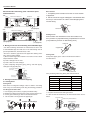
,QVWDOOLQJWKHPRXQWLQJSODWH
7RUTXHZUHQFK
$GMXVWDEOHZUHQFK
5HDPHUIRUGHEXUULQJ
WKDWWKHSDQHOLVFRPSOHWHO\OHYHODQGPDUNWKHERULQJSRLQWVRQWKH
ZDOO
6HFXUHWKHPRXQWLQJSODWHWRWKHZDOOZLWKVFUHZV
7KHPRXQWLQJSODWHVKRXOGEHLQVWDOOHGRQDZDOOZKLFKFDQVXSSRUW
WKHZHLJKWRIWKHLQGRRUXQLW
7HPSRUDULO\ VHFXUH WKH PRXQWLQJ SODWH WR WKH ZDOO PDNH VXUH
9DFXXPSXPS)RU5$
*DVOHDNDJHGHWHFWRU
,QVWDOODWLRQ0DQXDO
5HFRPPHQGHG PRXQWLQJ SODWH UHWHQWLRQ VSRWV
%XUUUHPRYDO
DQGGLPHQVLRQV
&RPSOHWHO\UHPRYHDOOEXUUVIURPWKHFXWFURVVVHFWLRQ
.
Wall
Mark on the middle of it
Space
to the
wall
150mm
above
RISLSHWXEH
3XWWKHHQGRIWKHFRSSHUWXEHSLSHLQDGRZQZDUGGLUHF
Wall
Gradienter
Space
to the
wall
150mm
above
WLRQDV\RXUHPRYHEXUUVLQRUGHUWRDYRLGGURSSLQJEXUUV
LQWRWKHWXELQJ
Pipe
Reamer
Left ¶PP
(Rear piping hole)
Right ¶PP
(Rear piping hole)
.
Mark on the middle of it
Wall
Gradienter
Space
to the
wall
150mm
above
Point down
Wall
Space
to the
wall
150mm
above
Left ¶PP
(Rear piping hole)
Right ¶PP
3XWWLQJQXWRQ
5HPRYHÀDUHQXWVDWWDFKHGWRLQGRRUDQGRXWGRRUXQLW
WKHQSXWWKHPRQSLSHWXEHKDYLQJFRPSOHWHGEXUUUHPRYDO
QRWSRVVLEOHWRSXWWKHPRQDIWHUÀDULQJZRUN
(Rear piping hole)
Flare nut
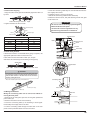
%RULQJDZDOOKROHDQGLQVWDOOLQJZDOOHPEHGGHGSLSH
)RUZDOOVFRQWDLQLQJPHWDOIUDPHRUPHWDOERDUGEHVXUHWRXVH
DZDOOHPEHGGHGSLSHDQGZDOOFRYHULQWKHIHHGWKURXJKKROHWR
)ODULQJZRUN
)LUPO\KROGFRSSHUSLSHLQDGLHLQWKHGLPHQVLRQVKRZQLQ
WKHWDEOHDERYH
,QVHUWDZDOOSLSHLQWRWKHKROH
,QVHUWDZDOOFRYHULQWRZDOOSLSH
Handle
"A"
SUHYHQWSRVVLEOHKHDWHOHFWULFDOVKRFNRU¿UH
%HVXUHWRFDXONWKHJDSVDURXQGWKHSLSHVZLWKFDXONLQJPDWH
ULDOWRSUHYHQWZDWHUOHDNDJH
%RUHDIHHGWKURXJKKROHRIPPLQWKHZDOOVRLWKDVDGRZQ
VORSHWRZDUGWKHRXWVLGH
Copper tube
Bar
Bar
Yoke
$IWHU FRPSOHWLQJ UHIULJHUDQW SLSLQJ ZLULQJ DQG GUDLQ SLSLQJ
FDXONSLSHKROHJDSZLWKSXWW\
Inside
Wall embedded pipe
(field supply)
Cone
Outside
Copper pipe
Clamp handle
Caulking
¶65
Red arrow mark
&DUU\RXWÀDULQJZRUNXVLQJÀDULQJWRRODVVKRZQEHORZ
Wall hole cover
(field supply)
Outside diameter
mm
inch
Wall embedded pipe
(field supply)
A
mm
)ODULQJZRUNDQGFRQQHFWLRQRISLSLQJ
)ODULQJZRUN
Ø6.35
1/4
0~0.5
Ø9.52
3/8
0~0.5
)ODULQJZRUN
0DLQ FDXVH IRU UHIULJHUDQW OHDNDJH LV GXH WR GHIHFW LQ WKH ÀDULQJ
Ø12.7
1/2
0~0.5
Ø15.88
5/8
0~1.0
Ø19.05
3/4
1.0~1.3
ZRUN&DUU\RXWFRUUHFWÀDULQJZRUNXVLQJWKHIROORZLQJSURFHGXUH
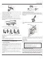
&XWWKHSLSHVDQGWKHFDEOH
8VHWKHSLSLQJNLWDFFHVVRU\RUSLSHVSXUFKDVHGORFDOO\
0HDVXUHWKHGLVWDQFHEHWZHHQWKHLQGRRUDQGWKHRXWGRRUXQLW
&XWWKHSLSHVDOLWWOHORQJHUWKDQWKHPHDVXUHGGLVWDQFH
&XWWKHFDEOHPORQJHUWKDQWKHSLSHOHQJWK
&KHFN
&RPSDUHWKHÀDUHGZRUNZLWK¿JXUHEHORZ
,IÀDUHLVQRWHGWREHGHIHFWLYHFXWRIIWKHÀDUHGVHFWLRQDQGUH
ÀDUHLW
Smooth all round
Inside is shiny without scratches
Copper
pipe
90e
= Improper flaring =
Slanted Uneven Rough
Even length
all round
Inclined Surface Cracked Uneven
damaged
thickness
,QVWDOODWLRQ0DQXDO
&RQQHFWLRQRISLSLQJ
$OLJQWKHFHQWHURIWKHSLSHVDQGVXI¿FLHQWO\WLJKWHQWKHÀDUHQXW
E\KDQG
,QVHUWWKHFRQQHFWLQJFDEOHIXOO\LQWRWKHWHUPLQDOEORFNDQGVH
FXUHLWWLJKWO\ZLWKVFUHZV
7LJKWHQLQJWRUTXH1PNJIP
6HFXUHWKHFRQQHFWLQJFDEOHZLWKWKHFRUGFODPS
$WWDFKWKHWHUPLQDOFRYHUUHDUSODWHEXVKLQJDQGDLULQOHWJULOOH
RQWKHLQGRRUXQLW
Indoor unit tubing
Flare nut
Pipes
&$87,21
7LJKWHQWKHÀDUHQXWZLWKDZUHQFK
%HVXUHWRUHIHUWRWKHZLULQJV\VWHPGLDJUDP
Open-end wrench (fixed)
&KHFNORFDOHOHFWULFDOUHJXODWLRQVIRUDQ\
VSHFL¿FZLULQJLQVWUXFWLRQVRUOLPLWDWLRQV
Flare nut
Wrench
ODEHOHGLQVLGHWKHIURQWSDQHO
Connection pipe
Indoor unit tubing
Terminal block
Outside diameter
mm
inch
Ø6.35
1/4
Ø9.52
3/8
Ø12.7
1/2
Ø15.88
5/8
Ø19.05
3/4
Torque
kg.m
1.8
4.2
5.5
6.6
6.6
Earth wire
Terminal cover
Screw
Screw
Cord clamp
'UDLQKRVHMXQFWLRQ
Connecting cable
,IGUDLQKRVHH[WHQVLRQRUHPEHGGHGGUDLQSLSLQJLVUHTXLUHGXVH
DSSURSULDWHSDUWVWKDWPDWFKWKHKRVHIURQWHQG
,QVHUWGUDLQKRVHLQWRWKHKDQGOHRIGUDLQSDQDQGMRLQ
GUDLQKRVHDQGFRQQHFWLQJKRVHDFFRUGLQJWRWKH¿JXUHE\
Shield pipe
Terminal block
Drain hose Inside the room
Extension drain hose
CAUTION
CAUTION
Insert the drain hose and drain cap into the drain port, making sure that it comes in contact with the back of the drain
port, and then mount it. If the drain hose is not connected
properly, leaking will occur.
• Attach the Insulation (Drain hose) to the drain hose.
Insulation (Drain hose)
Connecting cable
About 15 cm
Drain hose
70 mm
:LULQJ&RQQHFWLRQ
:LULQJ WKH FRQQHFWLQJ FDEOH FDQ EH FDUULHG RXW ZLWKRXW UH
10 mm
Earth line
PRYLQJWKHIURQWSDQHO
5HPRYHWKHDLULQOHWJULOOH2SHQWKHDLULQOHWJULOOHXSZDUGDQG
SXOOLWWRZDUG\RX
5HPRYHWKHWHUPLQDOFRYHUDQGFRUGFODPS
,QVHUW WKH FRQQHFWLQJ FDEOH RU DV DFFRUGLQJ WR ORFDO UHJXOD
WLRQVFRGHVLQWRWKHSLSHKROHRQWKHZDOO
3XOO WKH FRQQHFWLQJ FDEOH WKURXJK WKH FDEOH VORW RQ WKH UHDU
10 mm
50 mm
SDQHOVRWKDWLWSURWUXGHVDERXWFPRXWRIWKHIURQW
,QVWDOODWLRQ0DQXDO
,QVWDOOLQJLQGRRUXQLW
+RZWRUHSODFHWKHGUDLQSOXJDQGGUDLQKRVH
,QWKHFDVHRIEHQGLQJRUFXULQJUHIULJHUDQWSLSHVNHHSWKHIROORZ
LQJSUHFDXWLRQVLQPLQG
+RZWRUHPRYHWKHGUDLQFDS
&ODPSGUDLQFDSZLWKQHHGOHQRVHSOLHUVDQGSXOOit RXW
$EQRUPDOVRXQGPD\EHJHQHUDWHGLILPSURSHUZRUNLVFRQGXFWHG
'R QRW VWURQJO\ SUHVV WKH UHIULJHUDQW SLSHV RQWR WKH ERWWRP
IUDPH
'R QRW VWURQJO\ SUHVV WKH UHIULJHUDQW SLSHV RQ WKH IURQW JULOOH
HLWKHU
+RZWRUHPRYHWKHGUDLQKRVH
7KHGUDLQKRVHLVVHFXUHGLQSODFHE\DVFUHZ
Insulation
fixing screw
5HPRYHWKHVFUHZVHFXULQJWKHGUDLQKRVHWKHQ
SXOORXWWKHGUDLQKRVH
Drain hose
+RZWRDWWDFKWKHGUDLQFDS
,QVHUWKH[DJRQDOZUHQFKPP
No gap
Do not apply lubricating oil
(refrigerant machine oil) when
inserting the drain cap. If applied,
deterioration and leakage of the
drain plug may occur.
)LUPO\LQVHUWGUDLQFDS
+RZWRDWWDFKWKHGUDLQKRVH
7KHSLSLQJFDQEHOHDGRXWIURPULJKWULJKWUHDUOHIW andOHIWUHDU
5LJKWVLGHULJKWEDFNRUULJKWERWWRPSLSLQJ
$IWHUPDNLQJVOLWVRQWKHIURQWSDQHOZLWKDNQLIHRUVLPLODUWRRO
FXWWKHPRXWZLWKDSDLURIQLSSHUVRUDQHTXLYDOHQWWRRO
Insert a hexagon wrench
(4 mm)
,QVHUW WKH GUDLQ KRVH ¿UPO\ XQWLO WKH FRQQHFWRU FRQWDFWV WKH LQVXODWLRQ WKHQ
VHFXUHLWLQSODFHXVLQJWKHRULJLQDOVFUHZ
$IWHUPDNLQJVOLWVRQWKHIURQWSDQHOZLWKDNQLIHRUVLPLODUWRRO
FXWWKHPRXWZLWKDSDLURIQLSSHUVRUDQHTXLYDOHQWWRRO
$WWDFK WKH GUDLQ KRVH WR WKH XQGHUVLGH RI WKH UHIULJHUDQW SLSHV
ZLWKDQDGKHVLYHYLQ\OWDSH
:UDSWKHUHIULJHUDQWSLSHVDQGGUDLQKRVHWRJHWKHUZLWKDQ
inVXODWLRQWDSH
Slit
2YHUODSWKHFRQQHFWLRQSLSHLQVXODWLRQPDWHULDODQGWKHLQGRRU
Bind with vinyl tape
XQLWSLSHLQVXODWLRQPDWHULDO%LQGWKHPWRJHWKHUZLWKYLQ\OWDSHVR
WKDWWKHUHLVQRJDS
Plastic bands Insulation material
Right piping
Bottom
piping
Pipe (top)
Rear piping
Indoor unit drain hose
(bottom)
/HIWVLGHOHIWEDFNRUOHIWERWWRPSLSLQJ
,QWHUFKDQJHWKHGUDLQFDSDQGWKHGUDLQKRVH
(1)
(2)
(3)
(4)
CAUTION
In order to align the drain hose and drain cap, be
sure to insert securely and vertically. Incline insertion will cause water leakage.
When inserting, be sure not to attach any material
besides water. If any other material is attached, it
will cause deterioration and water leakage.
After removing drain hose, be sure not to forget
mounting drain cap.
Be sure to fix the drain hose with tape to the bottom
of piping.
:UDSWKHDUHDZKLFKDFFRPPRGDWHVWKHUHDUSLSLQJKRXVLQJ
VHFWLRQZLWKYLQ\OWDSH
Vinyl tape
(wide)
For left outlet piping, cut off the
piping outlet cutting groove
with a hacksaw.
Indoor unit
drain hose
Drain cap
Remove the drain cap by pulling
at the projection at the end of
the cap with pliers, etc.
Wrap with vinyl tape
Wrap with vinyl tape
Pipe
Vinyl tape(wide)
Drain hose
(5) Prevent drain water frozen under low temperature environment.
When installing indoor unit's drain hose outdoors, necessary
measure for frost protection should be taken to prevent drain
water frozen.
• Under low temperature environment (when outdoor temperature under 32 °F), after cooling operation is executed,
water in the drain hose could be frozen.
Once drain water is frozen, the drain hose will be blocked
and water leakage may be resulted for indoor unit.
Indoor
unit pipe
Connection
pipe
Indoor unit
Auxiliary pipes
Connecting
cable
Installation
plate
%XQGOH WKH SLSLQJ DQG GUDLQ KRVH WRJHWKHU E\ ZUDSSLQJ WKHP
ZLWKYLQ\OWDSHIRUHQRXJKWRFRYHUZKHUHWKH\¿WLQWRWKHUHDUSLS
LQJKRXVLQJVHFWLRQ
,QGRRUXQLWLQVWDOODWLRQ
3DVVWKHGUDLQKRVHDQGUHIULJHUDQWSLSHVWKURXJKWKHZDOOKROH
WKHQVHWWKHLQGRRUXQLWRQWKHPRXQWLQJSODWHKRRNVE\XVLQJWKH
PDUNLQJVDWWKHWRSRIWKHLQGRRUXQLWDVDJXLGH
,QVWDOODWLRQ0DQXDO
A Mounting plate
Drain-water hole
Bottom frame
Marking
Drain plug
Drain connecter
Hose (available commercially,
inner dia. 16mm)
6ZLQJWKHLQGRRUXQLWWRULJKWDQGOHIWWRFRQ¿UPWKDWLWLV¿UPO\
KRRNHGRQWKHLQVWDOODWLRQSODWH
5HIULJHUDQW3LSLQJ&RQQHFWLRQ
:KLOHSUHVVLQJWKHLQGRRUXQLWRQWRWKHZDOOKRRNLWDWWKHORZHU
SDUWRQWKHLQVWDOODWLRQSODWH
$OLJQWKHFHQWHURIWKHSLSLQJVDQGVXI¿FLHQWO\WLJKWHQWKHÀDUH
QXWE\KDQG
5HPRYHWKH9DOYHFRYHUIURPWKHXQLWE\ORRVHQLQJWKHVFUHZ
3XOOWKHLQGRRUXQLWWRZDUG\RXWRFRQ¿UPWKDWLWLV¿UPO\
KRRNHGRQWKHLQVWDOODWLRQSODWH
)RUGHWDFKLQJWKHLQGRRUXQLWIURPWKHLQVWDOODWLRQSODWHSXOOWKH
LQGRRUXQLWWRZDUG\RXZKLOHSXVKLQJWKHERWWRPXSDWWKHVSHFL
¿HGSODFHV
)LQDOO\WLJKWHQWKHÀDUHQXWZLWKWRUTXHZUHQFKXQWLOWKHZUHQFK
FOLFNV
Outdoor unit
Push
Liquid side piping
(Smaller diameter)
Push
5XQWKHGUDLQKRVHDWDGRZQZDUGVORSHGDQJOH
Do not rise the drain hose.
Do not form the drain hose
into the waved shape.
50 mm
or more
Torque wrench
Gas side piping
(Bigger diameter)
Do not put the
drain hose end
into water.
Do not put the drain
hose end in the
drainage ditch.
3XWZDWHULQWKHGUDLQSDQDQGPDNHVXUHWKDWWKHZDWHULVEHLQJ
GUDLQHGRXWVLGH
&DXWLRQ
,QVWDOOWKHGUDLQSLSHIRUSURSHUGUDLQDJH,PSURSHUGUDLQDJHFDQ
UHVXOWLQZDWHUGULSSLQJLQVLGHWKHURRP
2YHUODSWKHFRQQHFWLRQSLSHLQVXODWLRQPDWHULDODQGWKHLQGRRUXQLW
SLSH LQVXODWLRQ PDWHULDO %LQG WKHP WRJHWKHU ZLWK YLQ\O WDSH VR WKDW
WKHUHLVQRJDS
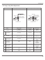
(YDFXDWLRQ
,QVWDOODWLRQRI2XWGRRU8QLW
'UDLQLQJWKH:DWHU
$IWHU WKH SLSLQJ KDV EHHQ FRQQHFWHG WR WKH LQGRRU XQLW SHUIRUP WKH
DLUSXUJH
+ROHVDUHSURYLGHGRQWKHEDVHSODWHRIWKHRXWGRRUXQLWWRHQ
VXUHWKDWWKHGHIURVWZDWHUSURGXFHGGXULQJKHDWLQJRSHUDWLRQVLV
$,5385*(
GUDLQHGRIIHI¿FLHQWO\
,IDFHQWUDOL]HGGUDLQLVUHTXLUHGZKHQLQVWDOOLQJWKHXQLWRQDEDO
XQLWXVLQJDYDFXXPSXPS
'RQRWXVHWKHUHIULJHUDQWLQWKHRXWGRRUXQLW
)RUGHWDLOVVHHWKHYDFXXPSXPSPDQXDO
FRQ\RUZDOO
,IWKHGUDLQSRUWLVFRYHUHGE\DPRXQWLQJEDVHRUÀRRUVXUIDFH
SODFH DGGLWLRQDO IRRW EDVHV RI DW OHDVW PP LQ KHLJKW XQGHU WKH
RXWGRRUXQLW¶VIHHW
,QFROGDUHDVGRQRWXVHDGUDLQKRVHZLWKWKHRXWGRRUXQLW
2WKHUZLVH GUDLQ ZDWHU PD\ IUHH]H LPSDLULQJ KHDWLQJ SHUIRU
PDQFH
(YDFXDWHWKHDLULQWKHFRQQHFWLQJSLSHVDQGLQWKHLQGRRU
$LUSXUJLQJZLWKYDFXXPSXPS
%H VXUH WR XVH D YDFXXP SXPS ZLWK FRXQWHUIORZ SUHYHQWLRQ
IXQFWLRQVRWKDWRLOLQVLGHWKHSXPSGRHVQRWÀRZEDFNLQWRWKH
DLU FRQGLWLRQHU SLSHV ZKHQ WKH SXPS VWRSV ,I RLO LQVLGH WKH
YDFXXPSXPSHQWHUVLQWRWKHDLUFRQGLWLRQHUFLUFXLWZKLFKXVHV
5$WURXEOHZLWKWKHUHIULJHUDWLRQV\VWHPPD\GHYHORS
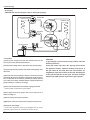
,QVWDOODWLRQ0DQXDO
&RQQHFWWKHFKDUJHKRVHIURPWKHPDQLIROGYDOYHWRWKHVHUYLFH
SRUWRIWKHJDVVLGHSDFNHGYDOYH
:LULQJ&RQQHFWLRQ
&RQQHFWWKHFKDUJHKRVHWRWKHSRUWRIWKHYDFXXPSXPS
2SHQIXOO\WKHORZSUHVVXUHVLGHKDQGOHRIWKHJDXJHPDQLIROG
YDOYH
&RQQHFWWKHFRQQHFWLRQZLUHVEHWZHHQWKHLQGRRUDQGRXWGRRU
XQLWV VR WKDW WKH WHUPLQDO QXPEHUV PDWFK 7LJKWHQ WKH WHUPLQDO
VFUHZVVHFXUHO\
2SHUDWHWKHYDFXXPSXPSWREHJLQHYDFXDWLQJ3HUIRUPHYDF
7KHVFUHZVDUHSDFNHGZLWKWKHWHUPLQDOERDUG
6WULSWKHLQVXODWLRQIURPWKHZLUHPP
XDWLQJ IRU DERXW PLQXWHV LI WKH SLSLQJ OHQJWK LV PHWHUV PLQXWHVIRUPHWHUVDVVXPLQJDSXPSFDSDFLW\RIOLWHUV
Terminal block
SHUPLQXWH&RQ¿UPWKDWWKHFRPSRXQGSUHVVXUHJDXJHUHDGLQJ
LV±N3D±FP+J
&ORVHWKHORZSUHVVXU