1
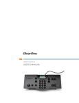
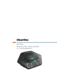
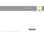
AccuMic™ User Manual
ClearOne Communications Inc. ~ 1825 Research Way, Salt Lake City, UT 84119 ~ tel 1-800-945-7730 ~ fax 1-800-933-5107
ii
AccuMic Microphone — Table of Contents
AccuMic Microphone — Introduction
Table of Contents
Introduction
Introduction . . . . . . . . . . . . . . . . . . . . . . . . . . . . . . . . . . . . . . . . . . . . . . . . . . . .1
The AccuMic™ VC and the AccuMic PC are highly-advanced microphones that provide high
quality, hands free audio. The AccuMic VC connects to video codecs to improve audio in
videoconferencing applications. The AccuMic PC connects to a computer to improve audio in
webconferencing applications. Each mic element features noise cancellation, automatic
gating control, PA adaptive mode, adaptive ambient mode and Gentner® Distributed Echo
Cancellation® to make communication between several people a natural, seamless experience.
Service and support . . . . . . . . . . . . . . . . . . . . . . . . . . . . . . . . . . . . . . . . . . . . . . . . . . . . . .1
Product returns . . . . . . . . . . . . . . . . . . . . . . . . . . . . . . . . . . . . . . . . . . . . . . . . . . . . . . . . .1
Unpacking . . . . . . . . . . . . . . . . . . . . . . . . . . . . . . . . . . . . . . . . . . . . . . . . . . . . . . . . . . . . .2
Product overview . . . . . . . . . . . . . . . . . . . . . . . . . . . . . . . . . . . . . . . . . . . . . . . . . . . . . . .3
AccuMic PC . . . . . . . . . . . . . . . . . . . . . . . . . . . . . . . . . . . . . . . . . . . . . . . . . . .4
Connecting the AccuMic PC . . . . . . . . . . . . . . . . . . . . . . . . . . . . . . . . . . . . . . . . . . . . . . .4
Configuring volume control settings . . . . . . . . . . . . . . . . . . . . . . . . . . . . . . . . . . . . . . . . .6
AccuMic VC . . . . . . . . . . . . . . . . . . . . . . . . . . . . . . . . . . . . . . . . . . . . . . . . . . . .9
Connecting the AccuMic VC . . . . . . . . . . . . . . . . . . . . . . . . . . . . . . . . . . . . . . . . . . . . . . .9
Operation . . . . . . . . . . . . . . . . . . . . . . . . . . . . . . . . . . . . . . . . . . . . . . . . . . . . .11
Using the AccuMic . . . . . . . . . . . . . . . . . . . . . . . . . . . . . . . . . . . . . . . . . . . . . . . . . . . . . .11
•
Push-button muting facilitates private discussions.
•
First-mic priority eliminates hollow "tunnel" sound by activating only the microphone
closest to the person speaking.
•
360-degree microphone coverage, adaptive noise cancellation and proprietary Gentner
Distributed Echo Cancellation provide clean, clear audio.
•
Expansion capability extends audio pick-up range to accommodate larger conferencing
rooms.
Troubleshooting . . . . . . . . . . . . . . . . . . . . . . . . . . . . . . . . . . . . . . . . . . . . . . . . .11
Service and support
Appendix . . . . . . . . . . . . . . . . . . . . . . . . . . . . . . . . . . . . . . . . . . . . . . . . . . . . . .12
If you need additional information on how to install, set up or operate your AccuMic VC or
AccuMic PC, please contact us. We welcome and encourage your comments so we can
continue to improve our products and better meet your needs.
Specifications . . . . . . . . . . . . . . . . . . . . . . . . . . . . . . . . . . . . . . . . . . . . . . . . . . . . . . . . . .12
Video codec compatibility . . . . . . . . . . . . . . . . . . . . . . . . . . . . . . . . . . . . . . . . . . . . . . . . .13
Warranty . . . . . . . . . . . . . . . . . . . . . . . . . . . . . . . . . . . . . . . . . . . . . . . . . . . . . . . . . . . . . .14
FCC Part 15 Compliance . . . . . . . . . . . . . . . . . . . . . . . . . . . . . . . . . . . . . . . . . . . . . . . . .16
Technical services
Telephone:
Fax:
E-mail:
Web site:
1-800-283-5936 (USA) or 1-801-974-3760
1-801-977-0087
[email protected]
www.clearone.com
Sales and customer service
Telephone:
Fax:
E-mail:
1-800-945-7730 (USA) or 1-801-975-7200
1-800-933-5107 (USA) or 1-801-977-0087
[email protected]
Product returns
AccuMic Installation and Operation Manual
ClearOne Part No. 800-157-001 May 2004 (Rev. 1.0)
All product returns require a return materials authorization (RMA) number. Please
contact ClearOne Technical Support before attempting to return your product. Make sure
you return all the items that shipped with your product.
© 2004 ClearOne Communications, Inc. All rights reserved. No part of this document may be reproduced in any
form or by any means without written permission from ClearOne Communications. Printed in the United States
of America. ClearOne Communications reserves specific privileges. Information in this document is subject to
change without notice.
Technical Services Group ~ 1-800-283-5936 (USA) ~ 1-801-974-3760
Technical Services Group ~ 1-800-283-5936 (USA) ~ 1-801-974-3760
1
2
AccuMic Microphone — Introduction
3
AccuMic Microphone — Introduction
Unpacking
Product overview
Carefully remove the AccuMic, cables and power supply from the packaging. Ensure that
you received the following parts:
Microphone pad
B
AccuMic VC
A
AccuMic VC
910-156-115
4 Plug RCA Cable with Breakout Power
830-156-003
Figure 3. Microphone pad
A. LEDs. Indicates when the microphones are activated.
B. Mute button. Mutes or unmutes the microphones.
AccuMic VC cable
100-240V In Line Power Supply with Power Cord
551-153-001
AccuMic PC cable
Manual
800-157-001
Figure 1. Unpacking the AccuMic VC
A
B
C
A
D
B
C
D
AccuMic PC
AccuMic PC
910-157-001
3.5 mm Cable with Breakout Power
830-157-001
E
E
Figure 4. AccuMic VC connector cable
100-240V In Line Power Supply with Power Cord
551-153-001
Manual
800-157-001
Figure 2. Unpacking the AccuMic PC
Note: ClearOne Communications is not responsible for product damage incurred during
shipment. You must make claims directly with the carrier. Inspect your shipment carefully for
obvious signs of damage. If the shipment appears damaged, retain the original boxes and
packing material for inspection by the carrier. Contact your carrier immediately.
Figure 5. AccuMic PC connector cable
A. Speaker Reference In.This plug provides an echo cancellation reference for the AccuMic,
ensuring audio is clear and echo-free.
B. Speaker Reference Out.This audio jack sends the far-side audio to the computer loud
speakers.
C. Mic Out.This audio jack sends local audio to the computer or codec for transmission to the
far-side participants.
D. Power supply. 12VDC.
E. 10-Pin Connector.This connector connects to the microphone pad.
Technical Services Group ~ 1-800-283-5936 (USA) ~ 1-801-974-3760
Technical Services Group ~ 1-800-283-5936 (USA) ~ 1-801-974-3760
4
AccuMic Microphone — AccuMic PC
5
AccuMic Microphone — AccuMic PC
To connect the AccuMic PC
AccuMic PC
1. Connect the 10-pin plug to the 10-pin connector on the AccuMic PC.
Connecting the AccuMic PC
2. Connect the Speaker Ref In (green) to the Line Out connector on the PC soundcard.
The AccuMic PC provides the highest quality audio to any desktop webconferencing system.
Featuring Distributed Echo Cancellation, automated gain control, gating control and
adaptive ambient mode, the AccuMic PC flawlessly picks up audio within a full 360 degree
coverage area. You can connect an AccuMic PC Extension Mic (part no. 910-157-010) to
expand the audio pick-up capabilities of the conferencing system.
3. Connect the Mic Out (red) to the Mic In on the PC soundcard.
4. Connect the Speaker Ref Out (green) to the Speaker jack cable from the speakers.
Note: Your speakers connect directly to the AccuMic PC to allow the echo cancellation to
work properly.
5. Connect the power connector to the power supply and plug the power supply into an outlet.
To connect an AccuMic PC Extension Mic
Line In
Note: Do not connect an AccuMic PC Extension Mic to an AccuMic VC. The AccuMic PC is
not compatible with the AccuMic VC and will not work properly.
1. Disconnect the first AccuMic PC from the power source.
2. Connect one end of the 10' (3 meter) mini-DIN cable to the 8-pin connector on the first
AccuMic PC.
PC Soundcard
3. Connect the other end of the cable to the 8-pin connector on the extension AccuMic PC.
4. Reconnect the first AccuMic PC to the power source.
Speaker
Line In/
Spkr In
Line Out/
Spkr Out
Mic In
5. Place the mic pads a suitable distance apart on the conference table to accommodate
meeting participants.
PC or Laptop
To Mic In
To Line Out
Speaker Ref In
(Green)
To Speaker Jack
Speaker Ref Out
(Green)
Mic Out
(Red)
To
Computer
To Power
First AccuMic
Power Connector
(Black)
Power Supply
8-Pin Connector
10' (3-meter) Mini-DIN Cable
20' Cable
10-Pin
Connector
8-Pin Connector
AccuMic PC
Figure 6. AccuMic PC connections
Extension AccuMic
Figure 7. Connecting an AccuMic PC Extension Mic
Technical Services Group ~ 1-800-283-5936 (USA) ~ 1-801-974-3760
Technical Services Group ~ 1-800-283-5936 (USA) ~ 1-801-974-3760
6
AccuMic Microphone — AccuMic PC
Configuring volume control settings
To ensure audio is heard clearly on both ends, you must configure the Volume Control
settings on your computer. You need to mute the near-end microphone balance to prevent
local audio feedback. (Note: This does not mute the AccuMic Microphone). You also need
to select and adjust the far-end microphone balance to ensure audio is being sent at a
proper level and far-end participants can hear you.
7
AccuMic Microphone — AccuMic PC
To mute near-end microphone balance
Note:You must mute the microphone balance to prevent local audio from looping back through
your loudspeakers and causing feedback problems.
1. Open Volume Control panel.
2. On the Options menu, click Properties.
To open the volume control panel
1. From the Start Menu, go to Settings, then Control Panel.
2. Double click the Sounds and Multimedia icon to open Sounds and Multimedia Properties.
3. Select the Audio tab and click Volume in the Sound Playback section.
Figure 10. Options menu
Figure 11. Playback
3. In the Properties window, click Playback.
4. Scroll down and select the Microphone check box.
5. Click OK.
The volume control window now displays the settings for Microphone Balance.
Figure 8. Sounds and multimedia properties
The Volume Control panel will open.
Figure 12. Mute microphone balance
6. Select the Mute check box for Microphone Balance.
Figure 9. Volume control
Technical Services Group ~ 1-800-283-5936 (USA) ~ 1-801-974-3760
Technical Services Group ~ 1-800-283-5936 (USA) ~ 1-801-974-3760
8
AccuMic Microphone — AccuMic PC
To select and adjust far-end microphone balance
Note: You must select Microphone in the Recording Control window to ensure audio is being
sent to the far end.
1. Open Volume Control panel.
2. On the Options menu, click Properties.
3. In the Properties window, click Recording.
9
AccuMic Microphone — AccuMic VC
AccuMic VC
Connecting the AccuMic VC
The AccuMic VC easily connects to most video codecs at the line level audio input and
output. Please refer to the table in the appendix for a list of video codecs that are
compatible. You can connect an optional AccuMic VC Extension Mic (kit part no.
910-156-117) to expand the sound pick-up capabilities of the conferencing system.
4. Select the Microphone check box.
To connect to a video codec
1. Connect the 10-pin end of the mini-DIN cable to the 10-pin connector on the AccuMic VC.
2. Connect the Speaker Ref In plug (white) to the video codec’s Audio Out jack.
3. Connect the Mic Out plug (red) to the video codec’s Audio In jack.
4. Using an RCA audio cable or an adapter (not included), connect the Speaker Ref Out
(white) plug to the television’s Audio In jack.
5. Connect the power connector to the power supply and plug the power supply into an outlet.
Figure 13. Recording
5. Click OK to open the Recording Control window.
6. Click the Select check box for Microphone Balance.
AUDIO
MIC
(PLUG IN POWER)
POWER
DC12V
100BASE-TX/
AUDIO OUT
10BASE-T
(MIXED)
IN
ISDN B
VIDEO
AUX2
ISDN C
AUX1
IN
1
ISDN A
1
2
IR OUT1
2
OUT
AUX OUT
IR OUT2
MONITOR OUT
Video Codec
TV or Video Monitor
To Audio In
To Audio
In
To Audio
Out
To Adapter
Speaker Ref In
(White)
Speaker Ref Out
(White)
To Power
Mic Out
(Red)
Figure 14. Recording control
Power Connector
(Black)
Power Supply
7. Use the volume slider to adjust the volume of the audio being sent to the far end.
10-Pin Connecter
AccuMic VC
Figure 15. AccuMic VC connections
Technical Services Group ~ 1-800-283-5936 (USA) ~ 1-801-974-3760
Technical Services Group ~ 1-800-283-5936 (USA) ~ 1-801-974-3760
10
AccuMic Microphone — AccuMic VC
To connect an AccuMic VC Extension Mic
Note: Do not connect an AccuMic VC extension to an AccuMic PC. The AccuMic VC is not
compatible with the AccuMic PC and will not work properly.
1. Disconnect the first AccuMic VC from the power source.
2. Connect one end of the 10' (3 meter) mini-DIN cable to the 8-pin connector on the first
AccuMic VC.
AccuMic Microphone — Operation
Operation
Using the AccuMic
The AccuMic is a plug-and-play microphone; the only function that is controlled manually is
Mute.
3. Connect the other end of the cable to the 8-pin connector on the extension AccuMic VC.
To mute the AccuMic
4. Reconnect the first AccuMic VC to the power source.
1. Press the Mute button (on top of the mic pad) to mute the AccuMic’s mic elements.The
LEDs will turn red.
5. Place the mic pads a suitable distance apart on the conference table to accommodate
meeting participants.
11
2. Press Mute again to unmute the mics.The LEDs will turn green.
Note: When using two connected AccuMics, pressing the Mute button on either unit will
mute/unmute both AccuMic mic pads.
To
Video Codec
Troubleshooting
First AccuMic
8-Pin Connector
If you have trouble with your AccuMic, the unit might not be properly connected or other
equipment might be malfunctioning. To begin, check the following:
•
The AccuMic power supply is plugged into a 100-240-volt electrical outlet.
•
The base connector cable from the power supply to the AccuMic is securely connected.
•
Connections to the video codec, television and PC are secure.
•
The LEDs on the top of the AccuMic illuminate in the direction of the participant
speaking. Participants need to be within 10 feet of the AccuMic.
10' (3-meter) Mini-DIN Cable
If you have trouble with the audio quality, ensure that:
8-Pin Connector
•
The Playback microphone balance mute option is selected. See page 7.
•
The Recording microphone balance is selected. See page 8.
If problems persist, please contact our Technical Services Group.
Extension AccuMic
Figure 16. Connecting an AccuMic VC Extension Mic
Technical Services Group ~ 1-800-283-5936 (USA) ~ 1-801-974-3760
Technical Services Group ~ 1-800-283-5936 (USA) ~ 1-801-974-3760
12
AccuMic Microphone — Appendix
AccuMic VC only
Specifications
8" x 6.5" x 1"
(20.3 x 16.5 x 2.5 cm)
13
Video codec compatibility
Appendix
Dimensions (L x W x H)
AccuMic Microphone — Appendix
Speaker Reference Out
AEC Tail Time
RCA jack
Nominal level -10dBu
130ms
Noise Cancellation
6dB attenuation
Weight
1 lb (.45 kg)
Operation
Temperature: 41–104° F
(5–40° C)
Humidity: 50–80%
Storage
Temperature: 41–158° F
(5–70° C)
Humidity: 10–90%
Power
12 VDC, 2.5A, 25W, center
positive
AccuMic VC Cables
(1) 35' (10.7 m) four plug
RCA cable
(1) Power In 12VDC, 2.5A,
25W
(1) Microphone Out
(1) Speaker Reference In
(1) Speaker Reference Out
AccuMic PC Cables
(1) 20' (6.1 m) four plug 3.5
mm plug
(1) Power In 12VDC, 2.5A,
25W
(1) Microphone Out
(1) Speaker Reference In
(1) Speaker Reference Out
Auto Mixer and Input
Configuration
Automatic gating control
PA adaptive mode
Adaptive ambient mode
Echo cancellation
Noise cancellation
First mic priority
NOM
Regulatory and Standards
FCC, CE, IC
Part Numbers
AccuMic VC 910-156-115
AccuMic PC 910-157-001
Microphones
AccuMic VC
Microphone Out
RCA jack
Nominal level: -10 dBu
Impedance: 100 ohm
AccuMic PC
Microphone Out
3.5 mm
Nominal level: -23 dBu
Impedance:100 ohm
3 elements, each with 120degree pickup range
Visual Feedback Indication
3 LEDs that indicate direction of audio pickup
Mute Button
Mutes all mic elements
A/D Conversion
Speaker Reference In
RCA plug
Nominal level: -10 dBu
Impedance: 200 ohm
24 bit, 16kHz
Optional AccuMic VC
Extension Mic Kit
Includes AccuMic VC
microphone and 10' (3 m)
extension cable.
910-156-117
Optional AccuMic PC
Extension Mic Kit
Includes AccuMic PC
microphone and 10' (3 m)
extension cable.
910-157-010
Figure 17. Video codec compatibility with AccuMic VC
Frequency Response
50Hz–7kHz
Technical Services Group ~ 1-800-283-5936 (USA) ~ 1-801-974-3760
Technical Services Group ~ 1-800-283-5936 (USA) ~ 1-801-974-3760
14
AccuMic Microphone — Appendix
Warranty
ClearOne Communications, Inc. (Manufacturer) warrants that this product is free of defects in both
materials and workmanship. Should any part of this product be defective, the Manufacturer agrees,
at its option, to:
A. Repair or replace any defective part free of charge (except transportation charges) for a period
of one year from the date the end user is invoiced for the product, provided the end user returns
the product to ClearOne Communications or an authorized ClearOne dealer according to the
Product Return and Repair Policy set forth below;
B. Furnish replacement for any defective parts in the product for a period of one year from the date
the end user is invoiced for the product, provided the end user provides proof of purchase that
demonstrates that the product is still within the warranty period. Replacement parts shall be
furnished without charge, except labor and transportation.
This warranty excludes assembled products not manufactured by the Manufacturer whether or not
they are incorporated in a Manufacturer product or sold under a Manufacturer part or model
number.
Product Return and Repair Policy
1. Return to Seller if Purchased Through an Authorized Dealer
AccuMic Microphone — Appendix
15
NO OTHER WARRANTY, EXPRESS OR IMPLIED, INCLUDING WARRANTIES OF
MERCHANTABILITY OR FITNESS FOR ANY PARTICULAR USE, APPLIES TO THE
PRODUCT. MANUFACTURER’S MAXIMUM LIABILITY HEREUNDER SHALL BE THE
AMOUNT PAID BY THE END USER FOR THE PRODUCT. No person or entity authorized to
assume any obligation or other liability in connection with the products. No action, regardless of
form, arising out of or relating to the product or this warranty, may be brought by end user more
than one (1) year after the cause of action has accrued.
Manufacturer shall not be liable for punitive, consequential, or incidental damages, expenses, or loss
of revenue or property, inconvenience, or interruption in operation experienced by the end user due to
a malfunction in the purchased product. No warranty service performed on any product shall extend
the applicable warranty period.
In case of unsatisfactory operation, the end user shall promptly notify the Manufacturer at the
address set forth below in writing, giving full particulars as to the defects or unsatisfactory
operation. Upon receipt of such notice, the Manufacturer will give instructions respecting the
shipment of the product, or such other matters as it elects to honor this warranty as above provided.
This warranty does not cover damage to the product during shipping and the Manufacturer assumes
no responsibility for such damage. All shipping costs shall be paid by the customer.
This warranty extends only to the original end user and is not assignable or transferable.This
warranty is governed by the laws of the State of Utah, without regard to the conflicts of interests
provisions thereof.
a. Proof of purchase date from reseller within warranty period must be provided by the end user.
b. Seller may, at its discretion, provide an immediate exchange or repair or may return the unit to
the Manufacturer for repair.
2. Return to Manufacturer
ClearOne Communications, Inc.
1825 Research Way
Salt Lake City, UT 84119
a. An RMA (return merchandise authorization) number must be issued to the end user from
ClearOne technical support.
b. The end user must return the product to ClearOne with proof of purchase (showing purchase
date) for a warranty claim, and display the RMA number on the outside of the shipping
package.
THIS WARRANTY IS VOID IF:
A. The product has been damaged by negligence, accident, act of God, or mishandling, or has not
been operated in accordance with the procedures described in the operating and technical
instructions; or,
B. The product has been altered or repaired by other than the Manufacturer or an authorized
service representative of the Manufacturer; or,
C. Adaptations or accessories other than those manufactured or provided by the Manufacturer have
been made or attached to the product which, in the determination of the Manufacturer, shall have
affected the performance, safety or reliability of the product; or,
D. The product’s original serial number has been modified or removed.
Technical Services Group ~ 1-800-283-5936 (USA) ~ 1-801-974-3760
Technical Services Group ~ 1-800-283-5936 (USA) ~ 1-801-974-3760
16
AccuMic Microphone — Appendix
17
AccuMic Microphone — Appendix
FCC Part 15 Compliance
Standard(s) to which Conformity is declared:
This equipment has been tested and found to comply with the limits for a Class A digital device,
pursuant to Part 15 of the FCC rules.These limits are designed to provide reasonable protection
against harmful interference when the equipment is operated in a commercial environment.This
equipment generates, uses, and can radiate radio frequency energy and, if not installed and used in
accordance with the instruction manual, may cause harmful interference to radio communications.
Operation of this equipment in a residential area is likely to cause harmful interference, in which case
the user will be required to correct the interference at his/her own expense.
89/336/EEC "Electromagnetic Compatibility (EMC) Directive":
EN 55022: 1994 (Emissions)
Specification for limits and methods of measure
ment of radio interference characteristics of
information technology equipment.
EN 61000-3-2:1995/A1/A2:1998
Part 3: Limits – Section 2: Limits for harmonic
current emissions.
EN 61000-3-3:1995
Section 3: Limitation of voltage fluctuations and
flicker in low voltage supply systems for equip
ment with rated current up to and including 16 A.
EN 55024: 1998 (Immunity)
Information technology equipment –
Immunity characteristics – Limits and methods of
measurement.Salt Lake City, Utah 84119
EN 61000-4-2: 1995/A1:1998
Electrostatic Discharge
EN 61000-4-3: 1996/A1:1998
Radiated RF Immunity
EN 61000-4-4: 1995
Electrical Fast Transients
EN 61000-4-5: 1995
Lightning Surge
1999/5/EC Radio equipment and
Telecommunications Terminal Equipment
(R&TTE) Directive
EN 61000-4-6: 1996
Conducted RF Immunity
EN 61000-4-8: 1993
Radiated Magnetic Field Immunity
Manufacturer’s Name:
ClearOne Communications, Inc.
EN 61000-4-11: 1994
Voltage Dips and Voltage Interruptions
Manufacturer’s Address:
1825 West Research Way
Salt Lake City, Utah 84119 U.S.A.
73/23/EEC "Low Voltage Directive (LVD)":
Model No.:
AccuMic VC
AccuMic PC
Changes or modifications not expressly approved by ClearOne Communications, Inc. could void the
user’s authority to operate the equipment.
European Compliance
This equipment has been approved in accordance with Council Directive 1999/5/EC "Radio
Equipment and Telecommunications Equipment."
Conformity of the equipment with the guidelines below is attested by the CE mark.
EC Declaration of Conformity
Application of Council Directive(s):
EN 60950: 1992
910-156-115
910-157-001
Technical Services Group ~ 1-800-283-5936 (USA) ~ 1-801-974-3760
Safety of Information Technology Equipment,
Including A1, A2, A3, A4 and A11 Electrical
Business Equipment.
Manufacturer
Legal Representative in Europe
Signature
Signature
Roger J. Midgley
Martin Offwood
Full Name
Full Name
Project Manager
Managing Director EMEA North
Position
Position
Technical Services Group ~ 1-800-283-5936 (USA) ~ 1-801-974-3760