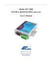
1
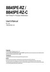
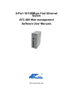
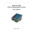
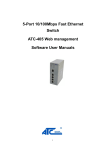
SHENZHEN ATC TECHNOLOGY CO., LTD. MODEL: ATC-3000 TCP/IP TO RS232/422/485 CONVERTER (Serial Device Server) User Manual Document name: Firmware : Updated Date : Version: ATC-3000 User Manual V6.1.0SP1050125R August 2014 Rev 2.0 Important Announcement The information contained in this document is the property of SHENZHEN ATC TECHNOLOGYCO., LTD. And is supplied for the sole purpose of the operation and maintenance of products of SHENZHEN ATC TECHNOLOGY CO.,LTD. No part of this publication is to be used for any other purposes, and it is not tobe reproduced, copied, disclosed, transmitted, stored in a retrieval system, or translated into any human or computer language, in any form, by any means, in whole or in part, without the prior express written consent of SHENZHEN ATC TECHNOLOGY CO., LTD. Published by SHENZHEN ATC TECHNOLOGYCO., LTD . Room 803, Block B, Building 4 Tian'an Cyber Park, Longgang District Shenzhen,China Latest product info: http://www.szatc.com Tel: +86 755 8345 3318 Fax: +86 755 28998985 E-mail: [email protected] [email protected] Copyright © 2014 SHENZHEN ATC TECHNOLOGY CO., LTD. All rights reserved. All other product names referenced here in are registered trademarks of their respective companies. ATC-3000 TCP/IP To RS-232/422/485 Converter Table of Contents 1 2 Introduction..........................................................................................................................................................................5 1.1 Packaging................................................................................................................................................................5 1.2 Main features.......................................................................................................................................................... 5 1.3 Specification............................................................................................................................................................5 1.4 Application example...............................................................................................................................................6 1.5 Hardware view........................................................................................................................................................ 7 1.6 Serial Connector Pinout........................................................................................................................................ 7 1.6.1 RS-232 Pinout........................................................................................................................................ 7 1.6.2 RS-422/485 Pinout.................................................................................................................................8 1.7 LED Indicator.......................................................................................................................................................... 8 1.8 Hardware Installation.............................................................................................................................................8 1.9 Factory default settings......................................................................................................................................... 8 1.10 Configuration Methods.......................................................................................................................................... 9 Configuration using Device Web Console......................................................................................................................9 2.1 Basic Setting.........................................................................................................................................................10 2.2 Network Setting.................................................................................................................................................... 11 2.3 Server Setting.......................................................................................................................................................13 2.4 HostList Setting.................................................................................................................................................... 13 2.5 Serial Turnnel 0 Setting...................................................................................................................................... 14 2.6 Connection Setting - TCP...................................................................................................................................17 2.7 Connection Setting - UDP.................................................................................................................................. 19 2.8 Password Setting................................................................................................................................................. 20 2.9 Load Default Setting............................................................................................................................................ 20 2.10 Apply Setting.........................................................................................................................................................21 2.11 Log Out.................................................................................................................................................................. 21 3 Configuration using Device Manager............................................................................................................................21 4 Configuration using Telnet..............................................................................................................................................22 4.1 Login the system.................................................................................................................................................. 23 4.2 Basic Settings.......................................................................................................................................................23 4.3 Connection 0 settings..........................................................................................................................................24 4.4 4.3.1 TCP Setting...........................................................................................................................................24 4.3.2 UDP Setting.......................................................................................................................................... 24 Network settings...................................................................................................................................................25 4.4.1 Use static IP address.......................................................................................................................... 25 4.4.2 Obtain IP Automatically.......................................................................................................................25 4.4.3 Ethernet Configuration........................................................................................................................ 26 4.5 Hostlist 0 settings.................................................................................................................................................26 4.6 Serial 0 settings....................................................................................................................................................26 4.7 Load factory default............................................................................................................................................. 26 4.8 User manager.......................................................................................................................................................27 4.9 View settings.........................................................................................................................................................27 4.10 Save and Reboot................................................................................................................................................. 27 4.11 Quit.........................................................................................................................................................................27 ATC-3000 User GuidePage 3 ATC-3000 TCP/IP To RS-232/422/485 Converter 5 How to reset ATC-3000 to default factory....................................................................................................................27 5.1 Reset by software................................................................................................................................................ 27 5.2 Reset by hardware...............................................................................................................................................29 ATC-3000 User GuidePage 4 ATC-3000 TCP/IP To RS-232/422/485 Converter 1 Introduction The Embedded Serial Server ATC-3000 is a gateway between Ethernet (TCP/IP) and serial signal communications. It can be built into any facilities or equipments, and converts any serial port to Ethernet network. By encapsulating serial data and transporting it over Ethernet, ATC-3000 allows bi-directional data transmission to be transparent between serial port and Ethernet. By using this unit, limited distance, point-to-point, direct serial connections can now be extended to the facility or equipment. In the industrial and manufacturing automation, ATC- 3000 can be embedded into most field devices, including PLCs, HMIs, Barcode Scanners, Data Terminals, Electronic Kanbans, UPS, Electronic Meters and Controller Automation Devices. These devices will soon be linked to the network. Existing Windows-based applications can access Serial-Ethernet devices by using Virtual COM software which creates virtual serial ports on the host computer mapping to the remote Serial Server over Ethernet. Flexible configuration options allow the unit to be setup remotely over Ethernet by Telnet, web browser, or other windows utilities. It is not only a transparent, cost-effective, network-enabled serial device, but also it is easy to install.. 1.1 Packaging Please check one package contains the following items: 1.2 ATC-3000 Module x 1 Power Adapter 9 VDC x 1 Product CD contains configuration utility x1 Quick Start Guide x 1 Main features 3-in-1 RS-232/422/485 interface Max.115.2Kbps. Serial interface and 10/100 Mbps Ethernet. Supports 4- and 2-wire RS485 with AUTO-SEND and built-in terminator. Terminal block accessories for easy RS-422/485 serial wiring. Support TCP/UDP Client/Server, Virtual COM mode. Monitor, manage and control industrial field devices remotely. Configuration: Web Server page, Device Manager, Telnet Console. Monitor IP configuration utility for Windows. Supports industrial 24 VDC power input and optional Power over Serial. PWR / ACT / SPEED / LINK indication Leds. 1.3 Specification Serial Interface Data Rates 300 bps to 230,400 bps Characters 5, 6, 7 or 8 data bits Parity Stop Bits Flow Control Connector Odd, Even, None, Space, Mark 1 or 2 None, Software: Xon/Xoff, Hardware: RTS/CTS DB9-DTE (Male), Removable 6 bit Terminal Block Network Interface Interface Connector Protocol Software ATC-3000 User GuidePage 5 Ethernet 10Base-T or 100Base-TX (Auto-Sensing) RJ45 ARP, UDP/IP, TCP/IP, PING/ICMP, DHCP, BOOTP, Auto IP, TFTP, SNTP, TELNET, HTTP, DNS, SMTP, PPP, LCP, PAP, CHAP, IPCP, PPPoE, HTTPS. ATC-3000 TCP/IP To RS-232/422/485 Converter Configuration Web Page,Telnet Virtual Com Windows port redirection software OS support Windows XP, Seven, Server 2003, Server 2008 System CPU Embedded high-performance 32-bit network processor, 32-bit RISC (NP7/9 series) Memory 32MB RAM, 16MB/32MB Code + 32KB Boot. Watchdog ASIC Hardware built-in. Power Input Voltage 9-24 VDC@500mA Power consumption 100mA max Physical Specifications Dimensions Weight Installation Operating temperature 1.4 95 x 66 x 26 mm 0.4 kg Panel/Wall, DIN-Rail mounting -40° to 70° C Application example Serial Turnneling (Peer connection) Using a method called serial tunneling, the ATC-3000 encapsulates serial data into packets and transports them over Ethernet. Using two ATC-3000 units, connected by a network, virtual serial connections can extend across a facility or around the world. Figure 1 - Serial Turnneling (Peer connection) application Direct UDP-TCP/IP or Redirector Configuration The Virtual COM Port software (VCOM) can be found in the CD in the package or download at www.szatc.com simplifies the integration process by extending the functionality of COM-port-based Windows applications. Virtual COM ports, mapped to remote device servers on the network, can replace direct serial connections. ATC-3000 User GuidePage 6 ATC-3000 TCP/IP To RS-232/422/485 Converter Figure 2 - Direct UDP-TCP/IP or Redirector Configuration application 1.5 Hardware view Figure 3 – Hardware view. 1.6 Serial Connector Pinout 1.6.1 RS-232 Pinout RS-232 connector is DB9 DTE Male PIN SIGNAL SIGNAL NAME I/O 1 No connect --- --- 2 RXD Receive Data In 3 TXD Transmit Data Out 4 No connect --- --- 5 GND Ground --- 6 No connect --- --- 7 RTS Request To Send Out 8 CTS Clear To Send In ATC-3000 User GuidePage 7 ATC-3000 TCP/IP To RS-232/422/485 Converter 9 No connect --- --- 1.6.2 RS-422/485 Pinout RS-422/485 Connector is removable 6-bit terminal block. From left of The terminal. RS-422/485 is described as following: 1.7 1.8 Terminal No. 1 2 3 4 5 6 RS-422 T+ T- R+ R- Vin GND RS-485 485+ 485- --- --- Vin GND LED Indicator LINK LED: SPEED LED: ACT LED: PWR LED: OFF – Ethernet disconnected. ON – Ethernet connected. OFF – Ethernet working in 10Mbps. ON – Ethernet working in 100Mbps. Flashes immediately when data is transmitting between Ethernet and Serial port. ON OFF – Power on. – Power off. Hardware Installation There are four basic steps to install one ATC-3000 1. Connect ATC-3000’s serial port to a serial device. 2. Connect ATC-3000 to Ethernet network. Use a standard straight-through Ethernet cable when one connect it to a Hub/Switch, one also can connect it to ones PC’s Ethernet port via a cross-over Ethernet cable for easy set up. However, in this case one need to make sure one PC is in the same network Sub-net as ATC-3000. 3. Connect ATC-3000 to power source using 9~24V DC Jack. 4. Supply the power. Placement options. One can mount ATC-3000 to a Wall/Panel or Din-Rail mounting. 1.9 Factory default settings ATC-3000 is shipped with main default settings shown in the following: IP address: Subnet: Gateway: Preferred DNS Server: Alternate DNS Server: Username: Password: Serial port: Link: 192.168.0.250 255.255.255.0 192.168.0.1 192.168.0.1 192.168.0.1 admin admin 9600 bps, None, 8, 1; None Flow control; Pack Control disabled; All of Buffer disabled. Type: TCP Server ; Local port : 27010 ; Remote Host : 0.0.0.0 ; Remote Port: 0. 1.10 Configuration Methods After installation, the ATC-3000 requires configuration. For the unit to operate correctly on a network, it must have a unique IP address on the network. There are three basic methods for logging into the ATC-3000 and assigning IP addresses and other configurable settings: By Device Web Console: Through a web browser (Google Chrome recommended), configure the ATC-3000 settings by enter the IP address of ATC-3000 in the URL. ATC-3000 User GuidePage 8 ATC-3000 TCP/IP To RS-232/422/485 Converter ( Refer to 2. Configuration using Device Web Console ) By Device Manager: Search IP, Configure the IP address and other network settings on the ATC-3000 using a Graphical User Interface (GUI) on a PC attached to a network. (Refer to 3. Configuration using Device Manager ) By Telnet: Using Telnet utility from Ms-DOS command prompt window to change configuration settings of ATC3000 (Refer to 4. Configuration using Telnet ) 2 Configuration using Device Web Console To access to the ATC-3000 unit’s web page, you have to know its IP address. If the unit is in factory default setting, the IP address will be 192.168.0.250. You need set up your computer to assign it a static IP address of the 192.168.0.X (X must be different 250) with a subnet mask of 255.255.255.0. This is necessary to ensure that your computer can communicate with your ATC-3000. If you forgot IP address of ATC-3000, please run Device Manager software in the CD then click Search button. Device Manager will show all ATC-3000 unit with IP address. From Web browser, enter IP address of the ATC-3000 in URL. A dialog box appears to prompt for a User Name and Password. Figure 4. Web Console login window Type in correct User name and Password then click Log In. Username: admin (default) / Password: admin (default). The Device Web Console displays. ATC-3000 User GuidePage 9 ATC-3000 TCP/IP To RS-232/422/485 Converter Figure 5 - Home Web page The main menu is in the left pane of the Web page window 2.1 Basic Setting The unit’s network values display when you select Basic Setting from the main menu. The following sections describe the configurable parameters on the Basic Setting page. Figure 6 – Basic settings From this page, you can set following parameters: Server name Name of ATC-3000 unit. It can be renamed by user with maximum length of 13 characters Time Include setting for Time Zone, Local Time and Time Sever. Web Console Select Enable to permit configuration the ATC-3000 by Web browser. ATC-3000 User GuidePage 10 ATC-3000 TCP/IP To RS-232/422/485 Converter Enable is the default. 2.2 Telnet Console Select Enable to permit configuration the ATC-3000 by Telnet. Enable is the default. Terminal Type Do not change If you are not necessary. VT100 is the default. Network Setting The unit's network values display when you select Network from the Main menu. The following sections describe the configurable parameters on the Network Settings page. IP configuration Figure 7 – IP configuration, Use the following IP config The IP configuration default setting is Use the following IP config Use the following IP config (Static IP address) You can manually assign an IP address to the unit and enter related network settings. To assign an IP address manually: 1. On the main menu click Network. 2. Select Use the following IP config. 3. Enter the following (as necessary): IP Address If DHCP is not used to assign IP addresses, enter it manually in decimal-dot notation. The IP address must be set to a unique value in the network. Subnet Mask A subnet mask defines the number of bits taken from the IP address that are assigned for the host part. Default Gateway The gateway address, or router, allows communication to other LAN segments. The gateway address should be the IP address of the router connected to the same LAN segment as the unit. The gateway address must be within the local network. Preferred DNS Server The DNS server allows the name of a remote machine to be resolved automatically. Enter the IP address of the DNS server. If the device is DHCP enabled, the DHCP server provides the DNS server IP address, which will override this configured value. Alternate DNS Server As a backup of Preferred DNS Server 4. When you are finished, click the OK button. 5. On the main menu, click Apply Settings. ATC-3000 User GuidePage 11 ATC-3000 TCP/IP To RS-232/422/485 Converter Obtain IP address automatically (Automatic IP address Configuration) An IP address can be assigned automatically. You then enter related network settings. Figure 8 – IP Configuration, Obtain IP address automatically To assign an IP address automatically: 1. On the main menu, click Network. 2. Select Obtain IP address automatically. 3. Enter the following (as necessary): BOOTP Select Enable to permit the Bootstrap Protocol (BOOTP) server to assign the IP address from a pool of addresses automatically. Enable is the default. DHCP Select Enable to permit the Dynamic Host Configuration Protocol (DHCP) to assign a leased IP address to the ATC-3000 unit automatically. Enable is the default. AutoIP Select Enable to permit the ATC-3000 to generate an IP in the 169.254.x.x address range with a Class B subnet. Enable is the default. DHCP Host Name Enter the name of the host on the network providing the IP address. 4. When you are finished, click the OK button. 5. On the main menu, click Apply Settings. Ethernet Configuration Figure 9 – Ethernet Configuration To specify how data will be transmitted: 1. On the main menu, click Network. 2. Enter the following (as necessary): Auto Negotiate ATC-3000 User GuidePage 12 With this option, the Ethernet port auto-negotiates the speed and duplex with the hardware endpoint to which it is connected. Select is the default. ATC-3000 TCP/IP To RS-232/422/485 Converter If this option is not selected, complete the fields that become available: Lock MAC Address 2.3 Speed: The speed of data transmission 10Mbps or 100Mbps. The default setting is 100Mbps. Duplex: The direction of data transmission. The default setting is Full. You can select to lock MAC address or unselect to modify it. Select is the default. 3. When you are finished, click the OK button. 4. On the main menu, click Apply Settings. Server Setting The unit's server values display when you select Server from the main menu. The following sections describe the configurable parameters on the Server Settings page. Figure 10 – Server Settings To configure the ATC-3000 device server settings: 1. On the main menu, click Server. 2. Configure or modify the following fields: ARP Cache Timeout (secs) CPU Performance Mode 2.4 When the unit communicates with another device on the network, it adds an entry into its ARP table. ARP Cache timeout defines the number of seconds (60-255s) before it refreshes this table. The default setting is 255. You can select Regular mode or High mode. The fault setting is Regular. HTTP Server Port This option allows the configuration of the web server port number. The valid range is 1-65535. The default setting is 80. MTU Size The Maximum Transmission Unit (MTU) is the largest physical packet size a network can transmit for TCP and UDP. The default setting is 1024 bytes and you can not change. 3. When you are finished, click the OK button. 4. On the main menu, click Apply Settings. HostList Setting The Hostlist only be used when ATC-3000 operate as a TCP Client. That means Acception InComing have to set to NO. Please refer to 2.6 Connection Setting – TCP for Acception InComing function. The ATC-3000 support up to three connections in the hostlist. The unit scrolls through the Hostlist until it connects to a device listed in the host list table and get three connections. After three connections established, the unit ATC-3000 User GuidePage 13 ATC-3000 TCP/IP To RS-232/422/485 Converter stops trying to connect to any others. If this connection fails, the unit continues to scroll through the table until the next successful connection. The host list supports a minimum of 1 and a maximum of 12 entries. Each entry contains an IP address and a port number. Figure 11 – Hostlist Settings To Setting the Hostlist: 1. On the main menu, click Hostlist. 2. Enter or modify the following fields: Retry Setting Retry Counter Enter the value for the number of times the ATC-3000 should attempt to retry connecting to the host list. Valid values are from 0 to 999. The default setting is 0. Retry Timeout Enter the duration (in milliseconds) the ATC-3000 should abandon attempting a connection to the host list. Valid values are from 0 to 999.The default setting is 0. Host Information 2.5 Host Address Enter or modify the host's IP address. Port Enter the target port number. Backup Link Select Enable to enable multi-connection (Maximum is 3). Select Disable to enable single connection only. The default setting is Disable. 3. When you are finished, click the OK button. 4. On the main menu, click Apply Settings. Serial Turnnel 0 Setting The Channel 0 configuration defines how the serial port responds to network and serial communication. ATC-3000 User GuidePage 14 ATC-3000 TCP/IP To RS-232/422/485 Converter Figure 12 – Serial Settings Serial Setting To configure the channel's serial settings: 1. On the main menu, click Serial Settings (under Channel 0) to display the Serial Settings window. 2. In the available fields, enter the following information: Channel 0 Enable / Disable Serial Port When selected, enables / disables communication through the serial port. The default is Enabled. Port Setting Protocol From the drop-down menu, select the protocol type for the selected channel such as RS232, RS422, RS485. The default setting is RS232. FIFO A FIFO (First In First Out) is a type of buffer, where the first byte to arrive is the first to leave. This drop-down menu can select 14, 8 or 4. The default setting is 8 bytes Flow Control Flow control manages data flow between devices in a network to ensure it is processed efficiently. Too much data arriving before a device is prepared to manage it causes lost or retransmitted data. This drop-down menu can select None, Software, Hardware. The default setting is None. Baud Rate The unit and attached serial device, such as a modem, must agree on a speed or baud rate to use for the serial connection. This drop-down menu can select valid baud rate from 300 to 230,400 bps. The default setting is 9600. Data Bits Indicates the number of bits in a transmitted data package. This drop-down menu can select valid values 5, 6, 7, 8 bits. The default setting is 8. Parity Checks for the parity bit. This drop-down menu can select ATC-3000 User GuidePage 15 ATC-3000 TCP/IP To RS-232/422/485 Converter NONE, ODD, EVEN, MARK, SPACE. The default setting is None. Stop Bits The stop bit follows the data and parity bits in serial communication. It indicates the end of transmission. This dropdown menu can select 1, 1.5, 2. The default setting is 1. Package Control Enable Packing Select to enable packing on the ATC-3000. Two firmware-selectable packing algorithms define how and when packets are sent to the network. The standard algorithm is optimized for applications in which the unit is used in a local environment, allowing for very small delays for single characters, while keeping the packet count low. The alternate packing algorithm minimizes the packet count on the network and is especially useful in applications in a routed Wide Area Network (WAN). Adjusting parameters in this mode can economize the network data stream. The default setting is Disabled. Idle Gap Time It is gap time between the bytes of a message. Select the maximum time for inactivity. This drop-down menu can select 10, 11, 12ms. The default setting is 12 milliseconds. Match 2 Byte Sequence Use to indicate the end of a series of data to be sent as one group. The sequence must occur sequentially to indicate end of the data collection to the ATC-3000. The default setting is No. Match Byte Use to indicate the end of a series of data to be sent as one group. Set this value to 00 if specific functions are not needed or leave blank. Send Frame Only After the detection of the byte sequence, indicates whether to send the data frame or the entire buffer. Select Yes to send only the data frame. The default setting is No. Send Trailing Bytes Select the number of bytes to send after the end-of-sequence characters. The default setting is None. Flush Input Buffer (Serial to Network) With Active Connect Select Yes to clear the input buffer with a connection that is initiated from the device to the network. The default setting is No. With Passive Connect Select Yes to clear the input buffer with a connection initiated from the network to the device. The default setting is No. At Time of Disconnect Select Yes to clear the input buffer when the network connection to or from the device is disconnected. The default setting is No. Flush Output Buffer (Network to Serial) With Active Connect ATC-3000 User GuidePage 16 Select Yes to clear the output buffer with a connection that is initiated from the device to the network. ATC-3000 TCP/IP To RS-232/422/485 Converter The default setting is No. 2.6 With Passive Connect Select Yes to clear the output buffer with a connection initiated from the network to the device. The default setting is No. At Time of Disconnect Select Yes to clear the output buffer when the network connection to or from the device is disconnected. The default setting is No. 3. When you are finished, click the OK button. 4. On the main menu, click Apply Settings. Connection Setting - TCP To configure a channel's TCP settings: 1. On the main menu, click Channel 0 / Connection. The Connection Settings window for the channel displays. Figure 13 – Connection Setting - TCP 2. In the available fields, enter or modify the following information: Connection protocol From the drop-down menu, select TCP Connection mode Passive Connection: Acception Incoming Select Yes to accept incoming connections. ATC-3000 work as a TCP/Server. Select No to don’t accept incoming connection. ATC-3000 work as a TCP/Client. The default setting is Yes. Active Connection: Active Connect Select None (default) to disable Active Connect. Otherwise, indicate the connection type from the drop-down list: With Any Character: Attempts to connect when any character is received from the serial port. ATC-3000 User GuidePage 17 ATC-3000 TCP/IP To RS-232/422/485 Converter With Start Character: Attempts to connect when it receives a specific start character from the serial port. The default start character is carriage return (CR in character or 0x0D in Hex). Auto Start: Automatically connects to the remote IP address and port after booting up. CTS Trigger: Attempts to connect when CTS pin is triggered from serial port. The default setting is NONE Start Character If Active Connect is set to With Start Character, enter the start character in this field (from 00 to FF). The default setting is Blank. Connection Configuration Local Port Enter the local port number, from 1-65535. The fault setting is 27010 Remote Port Enter the remote port number, from 1-65535. The fault setting is 0 Remote Host Enter the IP address of the remote device. DNS Query Period Limit time to queries DNS servers to lookup the name. The default setting is 1800 seconds. Connect Respond A single ‘C’ character is transmitted to the serial port when there is a change in connection state (TCP connection established). The default setting is None. Use Hostlist When Use Hostlist is set to YES, it only works if Acception Incoming is set to YES Please refer to 2.4 Hostlist Setting Select Yes to use Hostlist, select No to not use Hostlist. The default setting is No. Disconnect mode On Mdm_Ctrl_In Drop Set to Yes for the network connection to or from the serial port to disconnect (drop) when Modem Control In transitions from an asserted state to not asserted state. A single ‘D’ character is transmitted to the serial port when there is a change in disconnect state. The default setting is No. Hard Disconnect When set to Yes, the TCP connection closes even if the remote site does not acknowledge the disconnect request. Check EOT (Ctrl-D) Select Yes to drop the connection when Ctrl-D or Hex 04 is only detected going from the serial port to the network.Ctrl-D can be sent by Hyper Terminal The default setting is No. Inactivity Timeout Use this parameter to set an inactivity timeout. The unit drops the connection if there is no activity on the serial line before the set time expires. Enter time in the format mm:ss, where ‘m’ is the number of minutes and ‘s’ is the number of seconds. To disable the inactivity timeout, enter 00:00. The default setting is 4 minutes and 15 seconds 3. When you are finished, click the OK button. 4. On the main menu, click Apply Settings. ATC-3000 User GuidePage 18 ATC-3000 TCP/IP To RS-232/422/485 Converter 2.7 Connection Setting - UDP To configure a channel's UDP settings: 1. On the main menu, click Channel 0 / Connection. The Connection Settings window for the channel displays. 2. In the available fields, enter or modify the following information: Figure 14 – Connection Setting - UDP Connection protocol From the drop-down menu, select UDP Datagram mode Datagram type Select Uni-Cast to communicate directly from one point to another point. When selected Uni-Cast, you have to enter or modify parameters in Device Adress Table. Select Multi-Cast to communicate from one or more points to a set of other points as Broadcast UDP. When selected MultiCast, you have to enter or modify parameters in Endpoint Configuration. The default setting is Uni-Cast. Accept Incoming Select Yes to accept incoming connections. ATC-3000 work as a UDP/Server. Select No to don’t accept incoming connection. ATC-3000 work as a UDP/Client. The default setting is Yes. Endpoint Configuration These parameters use for Multi-Cast type only. Local Port Enter the local port number, from 1-65535. The fault setting is 0 Remote Port Enter the port number of the remote device, from 1-65535. ATC-3000 User GuidePage 19 ATC-3000 TCP/IP To RS-232/422/485 Converter The fault setting is 0 Net Segment Enter the IP address of Net segment. The fault setting is 0.0.0.0 Device Address Table These parameters use for Uni-Cast type only. This table uses similar to Use Hostlist. 2.8 No ATC-3000 support four ranges of IP address of device servers on the network Begin Address Begin IP address of a range of device servers End Address End IP address of a range of device servers Port Enter the port for each range Local port It is UDP Uni-Cast local port. 3. When you are finished, click the OK button. 4. On the main menu, click Apply Settings. Password Setting To set the password for ATC-3000 when access by Telnet or Web Console: 1. On the main menu, click Password Setting. Figure 15 – Password Settings 2.9 2. If you want to change User name, please type in new User name. The default is admin. 3. If you want to change Password, please type in correct Old Password then type in New Password anf Retype Password. 4. When you are finished, click the OK button. 5. On the main menu, click Apply Settings. Load Default Setting To Load Factory Default setting for ATC-3000: 1. On the main menu, click Load Defaults. ATC-3000 User GuidePage 20 ATC-3000 TCP/IP To RS-232/422/485 Converter Figure 16 – Load Factory default. 2. Click submit. Note: this function will rest all ATC-3000 settings to the factory default values. Be aware that previous setting will be lost. 3. When you are finished, click the OK button. 4. On the main menu, click Apply Settings. 2.10 Apply Setting To save and apply the configuration changes to the ATC-3000, from main menu, click the Apply Settings button then click Submit. Note: Clicking OK on each page does not change the configuration on the device. Clicking the OK button tells the ATC-3000 what changes to use; the Apply Settings button makes the changes permanent and reboots the ATC-3000. Figure 17 – Apply Setting 2.11 Log Out From main menu, click Log Out to log out user 3 Configuration using Device Manager Device manager is an utility to search IP address of ATC-3000 modules in the network. Open Device manager in the CD then click Search button physical Address. , it will show all ATC-3000 modules in network with IP Address and Figure 18 – Device manager window ATC-3000 User GuidePage 21 ATC-3000 TCP/IP To RS-232/422/485 Converter You can double-click on one ATC-3000 in the list to access. A dialog box appears to prompt for a User Name and Password. Figure 19 - Login After log-in to the ATC-3000, you can configure the ATC-3000 same as Web Console. Refer to 2 Configuration using Device Web Console Figure 20 - Config 4 Configuration using Telnet You can use Telnet utility to change configuration settings of ATC-3000. Before using telnet, you need to make sure that the Telnet Client on your computer are enabled How to enable Telnet Client in Windows XP? Start (button) > Control Panel > Add / Remove Programs > Turn Windows features on and off > check Telnet Client then press OK. How to enable Telnet Client in Windows 7? Start (button) > Control Panel > Programs and Features > Turn Windows features on or off > check Telnet Client then press OK. Note: You can refer to 2. Configuration by Device Web Console for description of every function of ATC-3000. ATC-3000 User GuidePage 22 ATC-3000 TCP/IP To RS-232/422/485 Converter 4.1 Login the system Open Ms-DOS command prompt window (press Windows key + r, type in “cmd” in the dialog appear then OK). Telnet to ATC-3000 using command "Telnet IP_address". With IP_address is IP address of ATC-3000. For example : Input Telnet 192.168.1.250 in Ms-DOS command prompt window. After telnet to ATC-3000, system prompts for a Username and password. The default Name is admin, Password is admin. Figure 21 - Login menu Note: if you forgot the password, please use Device Manager to find the IP. After verifying the password, the following terminal screen appears. Figure 22 - Main menu Note: Changes to networking parameters will take effect only when one save and reboot the ATC-3000. 4.2 Basic Settings From Main Menu, select “1” and Enter to visit Basic settings page. Figure 23 – Basic Settings This page gives you the general information of ATC-3000. ATC-3000 User GuidePage 23 ATC-3000 TCP/IP To RS-232/422/485 Converter 4.3 Connection 0 settings From Main Menu, select “2” and Enter to visit Connection 0 settings page. Figure 24 – Connection 0 Settings In this page you can change the network mode of ATC-3000. And then you can configuration the parameters of the mode which you choice. 4.3.1 TCP Setting From Connection 0 Setting page, select ‘1’ and enter to configure TCP for ATC-3000. Figure 25 – TCP Settings 4.3.2 UDP Setting From Connection 0 Setting page, select ‘2’ and enter to configure UCP for ATC-3000. Figure 26 – UDP Settings ATC-3000 User GuidePage 24 ATC-3000 TCP/IP To RS-232/422/485 Converter 4.4 Network settings From Main Menu, select “3” and Enter to visit Network settings page. Figure 27 – Network Settings 4.4.1 Use static IP address From Network Settings menu, select “1” and Enter to visit Use static IP address page. Figure 28 – Use static IP address 4.4.2 Obtain IP Automatically From Network Settings nenu, select “2” and Enter to visit Obtain IP Automatically page. Figure 29 – Obtain IP automatically ATC-3000 User GuidePage 25 ATC-3000 TCP/IP To RS-232/422/485 Converter 4.4.3 Ethernet Configuration From Network Settings menu, you can configure network parameters at Ethernet Configuration by select from ‘3’ to ‘8’. 4.5 Hostlist 0 settings From Main Menu, select “4” and Enter to visit Hostlist 0 settings page. Figure 30 – Hostlist Settings 4.6 Serial 0 settings From Main Menu, select “5” and Enter to visit Hostlist 0 settings page. Figure 31 – Serial 0 Settings 4.7 Load factory default From Main Menu, select “6” and Enter to visit Load factory default page. Select ‘y’ or ‘n’ to confirm Yes or No. ATC-3000 User GuidePage 26 ATC-3000 TCP/IP To RS-232/422/485 Converter 4.8 User manager From Main Menu, select “7” and Enter to visit User manager page. Figure 32 – User manage 4.9 View settings From Main Menu, select “8” and Enter to view all your settings for ATC-3000. 4.10 Save and Reboot From Main Menu, select “9” and Enter to save setting parameters and reboot the ATC-3000. After select Save and Reboot, connection to ATC-3000 lose and exit Telnet configuration. 4.11 Quit From Main Menu, select “10” and Enter to exit Telnet configuration. 5 How to reset ATC-3000 to default factory 5.1 Reset by software By Web brower Input ATC-3000’s IP address In URL and login device. And execute following steps: 1. From Main menu, Select Load Defaults 2. Select Submit. Figure 33 – Load factory default by Web Console 3. From new page appears, select Save/Restart to take affect. ATC-3000 will reset to default factory. ATC-3000 User GuidePage 27 ATC-3000 TCP/IP To RS-232/422/485 Converter Figure 34 – Save/Restart By Telnet Input Telnet IP_address with IP_address is IP address of ATC-3000 in Ms-DOS command prompt window and login. And execute following steps: 1. From Main Menu, select ‘6’ and press Enter key. 2. Type in ‘2’ and press Enter key. 3. Press any key to back Main menu. Figure 35 – Load factory default by Telnet 4. From Main menu, type ‘s’ and press Enter key to select Save and Reboot device to take effect. ATC-3000 will reset to default factory. ATC-3000 User GuidePage 28 ATC-3000 TCP/IP To RS-232/422/485 Converter Figure 36 – Save and Reboot 5.2 Reset by hardware If you forgot IP address of ATC-3000 and want to reset ATC-3000 to default factory, you can execute following steps: 1. Turn of the power supply. 2. Open the casing of ATC-3000 by removing two screws at side of ATC-3000. 3. Turn on the power supply. 4. Find the Reset button on the board (refer to below image). Figure 37 – ATC-3000 main board 5. Press and hold the Reset button until Link, Speed, ACT Leds are off (about 5 seconds). 6. Release the Reset button. ATC-3000 will reset to default factory. Warning: When you reset the device by this way, please contact the provider because this can tear warranty stamp is pasted on the ATC-3000. ATC-3000 User GuidePage 29