1
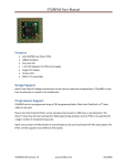
AP32PA3 User Manual Features 8 Bit RISC Processor o Atmel AVR® ISA compatible o 1K Byte Instruction RAM o 128 Byte Flash BIOS (JTAG writeable) o 32 Registers o 4 Level hardware stack o Up to 25MIPS speed Clock manager o 50MHz Crystal Oscillator o NCO for system clock o Dynamic PLL Supported by free AVR Basic Compiler 30 User I/O’s One user LED Single 3.3V Supply Easy solder: SMD or TH mountable Size 22.5x22.5x2 mm Pin Configuration AP32PA3-UM version 1.0 www.trioflex.com 6/4/2009 AP32PA3 User Manual Description AP32PA3 is a low power 8-bit Microcontroller with ISA mostly compatible to Atmel Classic AVR series. The microcontroller is implemented as Soft-Processor in Actel ProASIC3 Family lower Power Flash FPGA A3P060. Block Diagram TODO Pin Descriptions GND Ground pin. There is one extra GND pad close to the JTAG pads. VCC Supply voltage pin, should be connected to 3.3V supply, it is recommended to place an extra bypass capacitor close to the GND-VCC pins. PORT (P2,P4..P32) User port with 30 I/O Pins. All pins are configured as inputs at power on. Most pins have internal pull-up resistor enabled. Some port pins have alternate functions. TCK JTAG TAP TCK input, this pin is readable by the processor so it can optionally used as extra input only port. TDI JTAG TAP TDI input, this pin is readable by the processor so it can optionally used as extra input only port. TDO JTAG TAP TDO input, this pin is writeable by the processor, however the value will not be updated on the output pin unless there is external TAP master supplying TCK, and the TAP is in USER shift DR state. TMS JTAG TAP TMS input, never directly readable by the processor. AP32PA3-UM version 1.0 www.trioflex.com 6/4/2009 AP32PA3 User Manual User I/O There are total 30 I/O pins available. All I/O ports are configured as input at power on. Left Pin 1 2 3 4 5 6 7 8 Name GND P2 VCC P4 P5 P6 P7 P8 Pull Down Up Up Up Up Up Right Pin Name 17 P17 18 P18 19 P19 20 P20 21 P21 22 P22 23 P23 24 P24 Pull Up Up Up Up Up Up Up Up Top Pin 25 26 27 28 29 30 31 32 Name P25 P26 P27 P28 P29 P30 P31 P32 Bottom Pull Pin Name None 9 P9 Up 10 P10 Up 11 P11 Up 12 P12 Up 13 P13 Up 14 P14 Up 15 P15 None 16 P16 Pull Up Up Up Up Up Up Up Up Table 1 Pin to I/O port mapping Note: two additional input pins can be used from JTAG port pads. I/O Alternate Functions Some Ports have alternate functions that can be enabled by setting configuration registers. Port P2 Px Px P25 P32 P9 P16 Function PLL GLA Output PLL GLB Output PLL GLC Output OSCOUT1 OSCOUT2 OSCIO1 OSCIO2 Comment Programmable clock Programmable clock ? maybe use as programmable delay No pull up/down No pull up/down One pin oscillator 1 One pin oscillator 2 Table 2 I/O Alternate Functions The configuration hardware is limited and some resources are shared, so not all options are available at same time. AP32PA3-UM version 1.0 www.trioflex.com 6/4/2009 AP32PA3 User Manual I/O Multiplexer Each I/O pin (32 total) can be accessed by direct I/O Commands. Additionally all 32 pin inputs are connected to another “static” multiplexer. The output of that multiplexer can be connected to several function blocks. The multiplexer output can optionally be inverted. Resource Status Register PLL Timer/Counter Timer/Counter Port I/O Port I/O Input Bit 7 CLK Count Gate P25 (out) P32 (out) Usage As flag in short branches Alternate input clock for PLL Frequency measurement or pulse counting Pulse width measurement Two pin oscillator Two pin oscillator Table 3 I/O Multiplexer connectivity There is only one such static multiplexer so changing the pin index connected to it, will connect that pin to all functions that have selected the multiplexer output as its input. This is normally not desired, so only one function can be used at any one time. Some functions however can be used at same time too, as example when the multiplexer is used to make a two pin oscillator then the output can also be connected to the timer/counter block for frequency measurement. AP32PA3-UM version 1.0 www.trioflex.com 6/4/2009 AP32PA3 User Manual JTAG Pads/Header JTAG pins are routed to row of TH pads, the main purpose of them is factory programming. There is no need to connect anything to them. However two JTAG port pads (TCK and TDI) are readable by the processor and are directly mapped to the IO address space. It is also possible to update the Flash BIOS over the JTAG port by using some JTAG cable and software capable to play back SVF files. AP32PA3-UM version 1.0 www.trioflex.com 6/4/2009 AP32PA3 User Manual I/O Address Map TODO Address 3F 3F 2B 2A 29 28 20 20 1F 1F 1F 1E 00..1D Bit(s) 6..0 7 4..0 7..0 7..0 0 0 0 0 Name SREG PFLAG PFSEL CR3 CR2 CR1 NCO SR1 LED TCK TDO TDI Px R/W R/W R W W W W W R W R W R R/W Processor Status Register (Flags) Port Flag (output of static port input mux) Port Flag selector Control Register Control Register Control Register Clock setting: 0x01 lowest, 0x80 highest (F/2) Status Register Single bit I/O Ports P2..P32 Table 4 I/O Address Map AP32PA3-UM version 1.0 www.trioflex.com 6/4/2009 AP32PA3 User Manual Interrupts Processor master interrupt enable bit is not implemented (core interrupts always enabled). So enabling peripheral interrupts will start the interrupt system also. Currently only timer tick interrupt is available at vector 0x0001. AP32PA3-UM version 1.0 www.trioflex.com 6/4/2009 AP32PA3 User Manual Clock Manager TODO AP32PA3-UM version 1.0 www.trioflex.com 6/4/2009 AP32PA3 User Manual NCO A NCO is used to generated clock for the System. The MSB of the 9-Bit phase accumulator is used as NCO clock output. Phase increment is programmable (8 bit wide), it is mapped to I/O register space. A value of 0x80 yields to max clock output setting, what is input clock divided by 2, at input clock 50MHz the maximum output clock would be 25 MHz. NCO increment register is preloaded with value 0x01 at power up, giving lowest system. Writing 0 to NCO register will yield to minimal clock (not stopped clock). NCO 1 2 3 4 5 6 7 8 9 10 11 12 13 14 15 16 17 18 19 20 21 22 23 24 25 26 27 28 29 30 31 32 MHz 0.1953125 0.390625 0.5859375 0.781250 0.9765625 1.171875 1.3671875 1.5625 1.7578125 1.953125 2.1484375 2.34375 2.5390625 2.734375 2.9296875 3.125 3.3203125 3.515625 3.7109375 3.90625 4.1015625 4.296875 4.4921875 4.6875 4.8828125 5.078125 5.2734375 5.46875 5.6640625 5.859375 6.0546875 6.25 NCO 33 34 35 36 37 38 39 40 41 42 43 44 45 46 47 48 49 50 51 52 53 54 55 56 57 58 59 60 61 62 63 64 MHz 6.4453125 6.640625 6.8359375 7.03125 7.2265625 7.421875 7.6171875 7.8125 8.0078125 8.203125 8.3984375 8.59375 12.5 NCO 65 66 67 68 69 70 71 72 73 74 75 76 77 78 79 80 81 82 83 84 85 86 87 88 89 90 91 92 93 94 95 96 MHz NCO 97 98 99 100 101 102 103 104 105 106 107 108 109 110 111 112 113 114 115 116 117 118 119 120 121 122 123 124 125 126 127 128 MHz 24.609375 24.8046875 25 Table 5 NCO Frequencies Frequencies with no jitter are shown in bold. AP32PA3-UM version 1.0 www.trioflex.com 6/4/2009 AP32PA3 User Manual PLL The PLL Clock input is connected to 50 MHz clock from the on board oscillator at power up. It can be connected to either NCO output or any I/O pin by changing configuration register values. The PLL input frequency range is 1.5 to 350 MHz so some lower NCO frequencies cannot be used as input clock to the PLL. PLL Output Channel A Channel B Channel C Power up setting 100 MHz ? MHz ? MHz Comment P2 P? P? Table 6 PLL Default output frequencies VCO Gear (VCOSEL[2:1]) is set to xx at power on. VCOSEL[2:1] 00 01 10 11 VCO min (MHz) 24 33.75 67.5 135 VCO max (MHz) 43.75 87.5 175 350 Table 7 VCO Gear frequency ranges The PLL dynamic reconfiguration interface is connected to registers in the I/O space so it is possible to change the default values of the PLL parameters. For complete PLL description consult Actel ProASIC3 Handbook. AP32PA3-UM version 1.0 www.trioflex.com 6/4/2009 AP32PA3 User Manual AVR Compatibility The processor core is mostly compatible to Atmel “Classic AVR” RISC Microcontroller. Instructions/Functions not implemented WDR and Watchdog LPM – use LD to access ROM space AVR standard peripherals Differences in core behavior CPU Interrupts are always enabled (not controlled by SREG bit 7) Hardware stack is 4 level deep Instruction ROM is directly mapped to RAM space I/O and Registers are not accessible using LD/ST Instructions CBI/SBI can write Carry or T bit with optional inversion to Port pins SREG bit 7 is can be used as fast I/O flag input AP32PA3-UM version 1.0 www.trioflex.com 6/4/2009 AP32PA3 User Manual Performance AP32PA3 processor core and peripherals have been optimized for best bit-bang software controlled I/O performance, both for code compactness and execution speed. Any port pin can be set to 0 or 1 by using single instruction (CBI/SBI). Any port pin can be set to the value of CARRY or T flag with optional inversion. Those bit copy from any register bit to any I/O port is only two instructions. Status register bit 7 can be connected to any I/O port pin input, those making I/O pin value available for short branches. AP32PA3-UM version 1.0 www.trioflex.com 6/4/2009 AP32PA3 User Manual Special Features The processor has very little dedicated peripherals. There are however special dedicated circuits added that allow different features to be implemented with the assistance of the software. Pulse width Measurement Pulse width can be measured on any pin, minimum measurement step is 10ns. Frequency Measurement Frequency of an signal can be measured on any pin up to 200MHz. Capacitance Measurement Two pins (P9, P16) can be configured as one pin oscillators and the frequency can be measured, the frequency will depend on the extra capacitance added to those pins. Inductance Measurement There are two pins (P25, P32) that can be configured as an oscillator (internal inverted feedback), the frequency of the oscillation can be measured. The oscillator oscillates when external inductor is connected to those pins. Those two pins have no pullup or pulldown resistors enabled. Ambient Light Measurement There are two pins (P25, P32) without resistor pull up/down’s, those pins can be used to connect a normal visible LED to allow ambient (visible) light sensing applications. AP32PA3-UM version 1.0 www.trioflex.com 6/4/2009 AP32PA3 User Manual Bootstrap A small bootstrap code is programmed to the 128 byte Flash ROM, this code will boot the actual application program from some media or interface connected to the I/O Pins. The Flash ROM contents is copied to the MCU Instruction memory at address 0 at cold boot before the system internal reset is released. Because the Flash ROM size is only 64 instructions only one type of Bootstrap can be programmed to it. The bootstrap ROM is not reprogrammable from the application code, it can only be changed by JTAG Programmer. SD Card Boot This loader will load one sector from SD or micro-SD card to memory and execute the loaded code. SDHC and MMC Cards are not supported. The Card is initialized in SPI mode, so it must also be used in SPI mode by the application. UART Boot Simple UART loader can load the instruction memory and execute the loaded code. The code can be loaded to the RAM and executed by simply sending a special ASCII sequence to the UART, no handshaking is used or needed. SPI Master Boot This bootstrap will load code from Microwire EEPROM or SPI Flash serial ROM. Customizing Bootstrap On request customized bootstrap’s can be made, or optionally it is possible to reprogram the bootstrap code using a JTAG cable and tools. The best way to develop a custom bootstrap is to use the FPGA Evaluation package and some supported FPGA evaluation board. Updating the bootstrap with DATA2MEM is faster process than reprogramming the Flash ROM on the board. AP32PA3-UM version 1.0 www.trioflex.com 6/4/2009 AP32PA3 User Manual Programming AP32PA3 Core is mostly compatible to AVR Classic ISA, so any tool able to emit valid code for AVR could potentially be used. The small code space however almost fully excludes all high level language tools except the AVR Basic Compiler. AVR Basic This is the recommended compiler, libraries and examples are provided with the AP32PA3 SDK. // P2 = pin 2, P4 = pin 4, P32 = pin 32 P2 := 1; // set port pin to 1 P2 := 0; // clear port pin to 0 Writing to ports pins. PFSEL := SEL32; // select pin 32 as flag input IF PORTFLAG then // use port I/O in branch instruction ! LED := 1; // Lit on-board LED ELSE LED := 0; // LED off here END IF; Using the I/O Port multiplexer to sense port value in short branch instruction. In the example above the branch on port input value uses one instruction, normally it would have used two instructions. AP32PA3-UM version 1.0 www.trioflex.com 6/4/2009 AP32PA3 User Manual Demo Designs List of available demo designs. Some designs are also offered as ready to run bitstream’s for selected FPGA evaluation boards (not the AP32PA3 module). Character LCD “Hello” Demo is ready to run on Xilinx Spartan-3A Starterkit. AP32PA3-UM version 1.0 www.trioflex.com 6/4/2009 AP32PA3 User Manual Application Examples TODO FPGA Configurator The special bypass hardware makes it possible to copy bit streams from either SPI serial flash or SD card at bit rates up to 12.5 MBit/s under full software control. Of course after FPGA configuration additional features can be implemented by the program, like providing clock to the FPGA from the on board PLL, implementing a gateway to the SD Card, etc. FPGA configuration in slave serial, slave SPI or JTAG modes can be implemented. For this application it is normally sufficient to use the standard SD Card bootstrap, but of course a custom boot strap code could be developed as well to the specific requirements. UART to XYZ adapter UART or USB UART could be used to make a adapter to adapter to almost anything. UART interface consumes two I/O pins, so there would be 28 user I/O left for the program control. This type of application could bootstrap either from UART or from SD Card (depend on the bootstrap used). Programmable PLL TODO Frequency Meter TODO AP32PA3-UM version 1.0 www.trioflex.com 6/4/2009 AP32PA3 User Manual Development Tools TODO AVR Basic Compiler This is a special version of the original AVR Basic Compiler developed in 1997 by Silicon Studio Inc. Output file conversion utilities are provided, to generate files suitable for Actel FlashPro3 (UFC files) and Xilinx DATA2MEM (MEM files) for evaluation on Xilinx Boards. AVRA AVR Assembler This is a free open-source assembler compatible to AVRASM Assembler. Can be used to develop applications, include files are provided. NoFAT™ Utility AP32PA3 SD Card bootstrap can load code from file written to the SD Card by normal file copy, however the file need to be prepared by special tools. The NoFAT tool prepares and updates this special file. UART Companion Special tool to download firmware using the UART Bootstrap Flash BIOS, also works as terminal program later. Clock Configurator This tool allows to calculate all valid frequencies that can be obtained from the NCO and/or PLL. Settings are generated to configure the NCO and/or PLL. AP32PA3-UM version 1.0 www.trioflex.com 6/4/2009 AP32PA3 User Manual FPGA Evaluation AP32PA3 can be evaluated on general purpose FPGA Boards. List of supported FPGA Boards Xilinx Spartan-3A Starterkit Xilinx Spartan-3AN Starterkit (not tested, only bitstream’s are generated) Trenz TE300 with Demo base Board The evaluation is delivered as ready to download bitstream for the given FPGA development platform, AP32PA3 port pins are hardwired to the available peripherals and/or user headers on the target board. The actual features that can be directly evaluated depends the target board used. AP32PA3-UM version 1.0 www.trioflex.com 6/4/2009 AP32PA3 User Manual S3A-SK Demo This FPGA Evaluation package allows to test many features of the AP32PA3 using Xilinx Spartan-3A Starter kit as system emulation board. Almost all features are identical to the AP32PA3 board level product, with the exception of the JTAG and PLL features. Dynamic reconfiguration of the PLL is supported but it only changes the post VCO divider, not the settings of the PLL input or feedback dividers. The Flash BIOS image can be updated in the bitstream by using Xilinx DATA2MEM tool (Xilinx free WebPack installation is required for this). Several readymade bitstream’s are provided too with standard bootstrap code already embedded. For test purposes the instruction RAM can also updated with DATA2MEM, the lower 128 bytes are however overwritten by the content of the Flash BIOS. Peripherals that can be evaluated “On-board” LED – FPGA Init (Red LED LD11) UART – DB9 Board Connector J36 SD Card (Trioflex 6-pin micro-SD adapter is required) – PMod header J18 4 User I/O’s – PMod header J20 4 User I/O’s – PMod header J19 (connected to the OSCxx capable pins) Switch inputs connected to I/O LED’s connected to I/O Character LCD SPI – can be connected to various on-board components Audio output – Audio jack J29 (depend if we can have reasonable DAC hw) VGA Video – HD-DB15 Board Connector AP32PA3-UM version 1.0 www.trioflex.com 6/4/2009 AP32PA3 User Manual Function FPGA Init UART RX UART TX LCD D4 LCD D5 LCD D6 LCD D7 LCD E LCD RS Rotary Push Rotary A Rotary B SPI CLK SPI MOSI SPI MISO SPI SEL Reset Connection Red INIT LED LD11 J36 J36 J18 J18 J18 J18 Yellow AWAKE LED J20 J20 J20 J20 J19.1 J19.2 J19.3 J19.4 SW0 AP32 LED P2 P4 P26 P27 P28 P29 P30 P31 TCK Notes P10 P11 P12 P13 P15 P5 P6 P7 P8 P9 P16 P25 P32 P14 P17 P18 P19 P20 P21 P22 P23 P24 TDI TDO - For micro-SD adapter (or user I/O) Rotary knob switch (push for “1”) User I/O One pin oscillator 1 One pin oscillator 2 Two pin oscillator Two pin oscillator This not available on AP32 at all. Table 8 Pin to S3A-SK board function mapping The mapping on S3A-SK does not fully match the default mapping for factory bootstrap or CRUVI evaluation board mappings. So the firmware tested on S3A-SK must be recompiled for actual use on real AP32PA3 boards. AP32PA3-UM version 1.0 www.trioflex.com 6/4/2009 AP32PA3 User Manual AP32PA3-UM version 1.0 www.trioflex.com 6/4/2009 AP32PA3 User Manual TE300 Demo TE300 micro-module and TE300 Demo base board are used as evaluation platform. Function LED Push Button UART RX UART TX SD SD SD SD SPI SPI SPI SPI I2C I2C Connection TE300 LED TE300 Button AP32 LED Notes DB9 on baseboard Micro-SD Socket on baseboard Serial Flash on TE300 module P9 P16 P25 P32 One pin oscillator 1 One pin oscillator 2 Two pin oscillator Two pin oscillator Table 9 Pin to TE300 function mapping AP32PA3-UM version 1.0 www.trioflex.com 6/4/2009 AP32PA3 User Manual CRUVI™ EVAL20 Baseboard for evaluation STAMP32 form factor modules with the CRUVI™ concept modular design. AP32PA3 soldered to CRUVI™ baseboard (bottom view) Baseboard ready for boot from micro-SD Card (power adapter board not shown). AP32PA3-UM version 1.0 www.trioflex.com 6/4/2009 AP32PA3 User Manual Licensing AP32PA3 is normally delivered as factory pre-programmed FPGA on STAMP32 style module. The purchase price includes license for the IP Core use and tools. Some tools may have separate license and/or be limited or locked to specific usage. IP Core license The IP Core for the complete SoC system can also offered as VHDL source code. It is highly optimized and tuned for implementation in ProASIC3 A3P060, it can however also be used in other Actel FPGA device, or even in non Actel device. Use without modification in non-Actel FPGA would be not very reasonable as most other FPGA’s have more than 128 byte initialized memory so the Flash BIOS block makes no sense. AP32PA3-UM version 1.0 www.trioflex.com 6/4/2009 AP32PA3 User Manual List of Tables Table 1 Pin to I/O port mapping ................................................................................................................... 3 Table 2 I/O Alternate Functions .................................................................................................................... 3 Table 3 I/O Multiplexer connectivity ............................................................................................................ 4 Table 4 I/O Address Map .............................................................................................................................. 6 Table 5 NCO Frequencies .............................................................................................................................. 9 Table 6 PLL Default output frequencies ...................................................................................................... 10 Table 7 VCO Gear frequency ranges ........................................................................................................... 10 Table 8 Pin to S3A-SK board function mapping .......................................................................................... 21 Table 9 Pin to TE300 function mapping ...................................................................................................... 23 AP32PA3-UM version 1.0 www.trioflex.com 6/4/2009 AP32PA3 User Manual Appendix A: References TODO Actel ProAsic3 Handbook ST32PA3 Datasheet AP32PA3-UM version 1.0 www.trioflex.com 6/4/2009