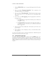
1
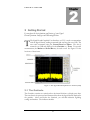
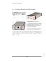
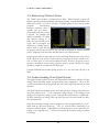
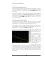
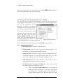
SgLabs www.sglabs.it email: [email protected] Tel. +39 0755149360 TEST EQUIPMENT PLUS Signal Hound USB-SA44B User Manual SgLabs TEST EQUIPMENT PLUS Signal Hound USB-SA44B User Manual 2010, Test Equipment Plus 35707 NE 86th Ave Phone (360) 263-5006 • Fax (360) 263-5007 Version 2.11A Table of Contents 1 PREPARING FOR USE ............................. 1 1.1 Initial Inspection ............................................... 1 1.2 Software Installation ........................................ 2 1.2.1 System Requirements................................. 2 1.2.2 Install the Signal Hound Software............. 2 1.3 2 2.1 3.1.4 3.1.5 3.1.6 Measuring Low Level Signals .................17 Measurements Near DANL ...................17 Capturing Pulsed or Intermittent Signals 17 3.2 Viewing Modulation........................................17 3.2.1 Capturing Pulses in Zero Span .................18 3.3 Measuring Channel Power.............................19 3.4 Understanding Your Signal Hound..............19 3.5 Measuring Harmonics ....................................20 3.6 Measuring Phase Noise...................................20 Running the software for the first time ......... 2 GETTING STARTED.................................. 4 The Graticule ..................................................... 4 2.2 The Control Panel............................................. 5 2.2.1 FREQUENCY CONTROLS ..................... 6 2.2.2 SPAN CONTROLS.................................... 6 2.2.3 AMPLITUDE CONTROLS ...................... 6 2.2.4 MARKER CONTROLS ............................ 6 2.2.5 BANDWIDTH CONTROLS..................... 7 2.2.6 TRACE CONTROLS................................. 8 2.2.7 TRIGGER AND SWEEP CONTROLS ... 8 2.2.8 ADDITIONAL CONTROLS .................... 9 2.2.9 TRACKING GENERATOR CONTROLS9 2.3 The Menu ........................................................... 9 2.3.1 FILE............................................................. 9 2.3.2 EDIT.......................................................... 10 2.3.3 VIEW ........................................................ 10 2.3.4 PRESETS .................................................. 10 2.3.5 SETTINGS................................................ 10 2.3.6 TRACE...................................................... 11 2.3.7 Utilities...................................................... 11 2.3.8 HELP ......................................................... 12 3.7 Using the Measuring Receiver Utility ..........21 3.7.1 Audio Analysis Controls ..........................21 3.7.2 The Analyzer Data Window.....................22 3.8 3.9 Limitations of the Signal Hound ...................23 3.9.1 RBW Limitations ......................................23 3.9.2 IF Feed-Through .......................................23 3.9.3 LO Leakage ...............................................23 3.9.4 Sweep Time...............................................23 4 4.1.1 4.1.2 4.1.3 4.1.4 4.1.5 4.1.6 4.2 2.4 The Status Bar ................................................. 13 2.5 The Signal Hound Front & Rear Panels ..... 14 3 TAKING MEASUREMENTS .................... 15 3.1 Measuring Frequency and Amplitude......... 15 3.1.1 Using the Markers .................................... 15 3.1.2 Example: Identify a Signal’s Frequency and Amplitude ........................................................... 16 3.1.3 Using the DELTA Marker ....................... 16 EMC Measurements .......................................23 ADDITIONAL FEATURES ....................... 25 Save / Recall State ....................................25 Printing ......................................................25 Listening to Demodulated Audio.............26 Using an External Timebase ....................26 Using an External Trigger ........................26 Using Sync Out .........................................27 Using Limit Lines ............................................27 5 THEORY OF OPERATION ...................... 28 5.1.1 The Four Sweep Modes............................28 5.1.2 Reducing Spurious and Residual Responses...................................................................29 5.1.3 IF-to-Bits Receiver....................................29 5.1.4 IF and RBW Selection ..............................29 6 TROUBLESHOOTING ............................. 31 7 CALIBRATION AND ADJUSTMENT...... 33 8 SPECIFICATIONS.................................... 34 8.1 Frequency......................................................... 34 8.2 Amplitude (RBW ≤100KHz) ......................... 34 8.3 Sweep ................................................................ 35 8.4 Measuring Receiver ........................................ 35 8.5 Inputs and Outputs......................................... 35 8.6 Environment .................................................... 35 8.7 Calibration ....................................................... 36 8.8 Adjustments ..................................................... 36 8.9 Optional Accessories....................................... 36 8.10 FCC Compliance......................................... 36 8.11 CE Compliance ........................................... 36 9 REVISION HISTORY ............................... 37 10 WARRANTY AND DISCLAIMER ............ 38 10.1.1 Warranty ............................................... 38 10.1.2 Warranty Service .................................. 38 10.1.3 Limitation of Warranty ........................ 38 10.1.4 Exclusive Remedies ............................. 39 10.1.5 Certification .......................................... 39 10.1.6 Credit Notice......................................... 39 P R E P A R I N G F O R U S E Chapter 1 1 Preparing For Use Unpacking your Signal Hound and Installing Software T he The Signal Hound USB-SA44B is a USB-based 1 Hz to 4.4 GHz economy spectrum analyzer and measuring receiver with an RF preamplifier. Using recent innovations in RF technology, the Signal Hound has the sensitivity, accuracy and dynamic range you’d expect in a unit many times its cost. The Signal Hound is powered from the USB cable, eliminating the need for a separate power supply. Measuring less than 8 inches long and weighing only ten ounces, the Signal Hound can be used virtually anywhere! 1.1 Initial Inspection Check your package for shipping damage before opening. Your box should contain a USB cable, a CD-ROM, and a Signal Hound USB-SA44B. 1 P R E P A R I N G F O R U S E 1.2 Software Installation The Signal Hound is operated from a Windows® based PC using our application software. 1.2.1 System Requirements The Signal Hound software and drivers are compatible with Windows® operating systems. You must have at least 500 MB of free disk space, 2 GB of RAM, USB 2.0 and a 2 GHz processor, and internet access for a one-time calibration data download. Your computer must have the "Microsoft .net framework" version 3.5 or newer installed. If you have Windows 7 or Windows Vista with automatic updates turned on, you should already have this. If you do not already have a newer version, please install it from the CD. The software connects to the internet to download a temperature correction file. An internet connection is required the first time you run the software. 1.2.2 Install the Signal Hound Software • Run setup.exe from the CD by double-clicking the file. Follow the directions on the screen. You must have administrator privileges. • The Signal Hound software is now installed. You must reboot your PC before the Signal Hound will operate correctly. • Before launching the software, connect the Signal Hound to any available USB 2.0 port using the included USB cable. Wait while Windows installs the necessary device drivers. This takes several seconds. Once you see “The hardware is ready to use”, continue. 1.3 Running the software for the first time 1. If your Signal Hound is not yet plugged in to your computer's USB port, connect the Signal Hound to any available USB 2.0 port. Wait while Windows installs the necessary device drivers. This takes several seconds. Once you see “The hardware is ready to use”, continue. 2. Launch the Signal Hound application from the Start Menu or desktop. The first time the software runs, temperature corrections are downloaded from the internet and calibration data is transferred from the Signal Hound to the computer. This takes about 10 seconds. 3. You may begin using the Signal The Signal Hound’s RF input is DC-coupled. Hound Spectrum Analyzer now. If you Always use a DC block wish to optionally verify basic when your signal has AC and DC combined. functionality, proceed with the next steps. 4. Connect the “SELF TEST” BNC 2 P R E P A R I N G F O R U S E output to the RF IN SMA input using a BNC cable and BNC-to-SMA adapter. 5. From the GUI, select Utilities SELF TEST. 6. Observe that all self tests pass. If not, see the Troubleshooting section. 3 G E T T I N G S T A R T E D Chapter 2 2 Getting Started Learn about the basic functions and features of your Signal Hound Spectrum Analyzer and Measuring Receiver T The Signal Hound Graphical User Interface, or GUI, is used to communicate with the Signal Hound, sending commands and receiving data over USB. The user sends commands using the Control Panel and Menu. The data is returned over USB and displayed in the Graticule as a Trace. For specific measurements, the Marker and Status Bar may be used as well. See Figure 1 for the locations of these items. Figure 1 – The Signal Hound Graphical User Interface (GUI) 2.1 The Graticule The Graticule contains ten vertical and ten horizontal divisions to display trace data. The trace data is the processed and formatted data from the Signal Hound, displayed in the graticule. Above and below the Graticule, you will find indicators regarding settings and markers. The indicators include: 4 G E T T I N G S T A R T E D ⇒ REF: Reference level, top left. The reference level is the signal amplitude for the top Graticule line. ⇒ DB/div: Amplitude scale, near top left, in dB per division of the Display Window. In Linear scale, this will be mV/div. ⇒ ATTEN: Attenuator setting, top center. The internal electronic attenuator may be set to 0, 5, 10, or 15 dB. ⇒ INT / EXT REF: Top right. Indicates whether internal or external reference is selected. ⇒ START, CENTER, STOP: Bottom left, center and right of Display Window. Start, center, and stop frequencies, representing the frequency of the left, center, and right Graticule lines, respectively. ⇒ RBW: Selected Resolution Bandwidth, calculated from FFT size and sample rate Markers may be placed anywhere on the trace by left-clicking inside the graticule at the desired location. ⇒ VBW: Video Bandwidth currently selected. ⇒ SPAN: Difference between start and stop frequencies. ⇒ SWP: In zero-span, this is the exact sweep time from left to right. In all other spans this is time elapsed during the last sweep. ⇒ MARKER DATA will appear along the bottom of the graticule. ⇒ Annunciators: In the top left corner of the graticule, you may see some letters. These will notify you when readings are uncalibrated or a special setting exists such as image rejection off. See the HELP menu for additional information. 2.2 The Control Panel The control panel is the section on the right-hand side of the Graphical User Interface, or GUI. It has buttons for the most common user commands. Frequency, span, reference level, trigger, video and resolution bandwidth processing, sweep and marker commands are available here. Try this: Click CENTER FREQ, then using the mouse, click the buttons 1, 2, 3, MHz. You should see your center frequency change to 123 MHz. Now click SET SPAN, 5, 0, KHz. Watch as start and stop frequencies and span are updated in the lower section of the graticule. 5 G E T T I N G 2.2.1 S T A R T E D FREQUENCY CONTROLS ⇒ CENTER FREQ sets the center frequency of the sweep. When clicked, a popup will open, allowing you to enter the frequency using the mouse or keyboard. ⇒ STEP sets the frequency increment / decrement amount. Default is 10 MHz. ⇒ The UP and DOWN arrows will change the center frequency by a preset STEP amount. ⇒ START and STOP set the sweep’s start and stop frequencies, respectively. 2.2.2 SPAN CONTROLS ⇒ SET SPAN sets the span of the sweep, the difference between start and stop frequencies. The center frequency is held constant. ⇒ The UP and DOWN arrows will step through the default spans from 100 Hz to 1 GHz, in a 1,2,5 pattern. ⇒ ZERO SPAN changes the x-axis on the graticule to time instead of frequency. The y-axis may be demodulated amplitude or frequency. When this button is clicked, a popup will open, allowing the user to select amplitude (AM) or frequency (FM) for the y-axis. ⇒ FULL SPAN sets the span to its maximum. 2.2.3 AMPLITUDE CONTROLS ⇒ REFERENCE LEVEL sets the power level for the top graticule line. You may select EMC units here, including V/m, mW/cm2, etc, in log or linear mode. ⇒ The UP and DOWN arrows will change the reference level by a preset amount, equal to dB/div. ⇒ ATTEN sets the internal electronic attenuator to 0, 5, 10, or 15 dB. ⇒ dB/div sets the scale for the y-axis. It may be set to any positive value. o 10 dB /div is default, giving a full scale range of 100 dB. ⇒ LIN sets the amplitude scale to linear "voltage" units, instead of logarithmic. 2.2.4 MARKER CONTROLS ⇒ The left-right arrows scroll between the available markers. Markers 1 thru 9 are available, each with its own reference point. You may place a marker 6 G E T T I N G S T A R T E D by simply clicking on the trace. Fine-tune a marker's placement using your mouse wheel. ⇒ PEAK moves the marker to the highest amplitude signal on the graticule. ⇒ DELTA anchors the marker’s reference (e.g. 1R) at the marker’s current position. Move the marker by left-clicking and/or using the mouse wheel to make differential measurements relative to the reference. ⇒ UPDATE ON/OFF When Update is ON, the marker’s amplitude updates each sweep. When OFF, the marker’s amplitude does not update unless it is moved. ⇒ OFF turns the marker off and back to default The marker sequence of OFF, PEAK, DELTA is good for reliable dBc measurements. settings. ⇒ MKR to CF sets CENTER FREQUENCY to the current marker position. ⇒ MKR to REF LVL sets the REFERENCE LEVEL to the current marker position. 2.2.5 BANDWIDTH CONTROLS ⇒ Res BW: This controls the resolution bandwidth (RBW). For each span, a range of resolution bandwidths may be used. The resolution bandwidth controls the Intermediate Frequency (IF) bandpass filter. o Resolution bandwidths are available from 0.1 Hz to 250 KHz, typically in powers of 2. A 5 MHz RBW is also available for limited functions. o The SPAN (stop - start frequencies) will affect which RBWs are available. o The SPAN and RBW determine the number of data points in a sweep, roughly 2.5 x SPAN/RBW. ⇒ Video BW: This controls the video bandwidth (VBW). After the signal has been passed through the RBW filter, it is converted to an amplitude. This amplitude is then filtered by the Video Bandwidth filter. This is implemented as a simple “rectangle" averaging window. o Video bandwidths are available from 0.1 Hz to 250 KHz, typically in powers of 2. VBW must be equal to or less than RBW. 7 G E T T I N G S T A R T E D ⇒ AUTO: To reset either RBW or VBW to automatically use the default setting, for each span, click AUTO. ⇒ Video Detector Settings: As the video data is being processed, the minimum, maximum, and average amplitudes are stored. maximum, average, or Min & Max may be displayed. Minimum, ⇒ When converting from I/Q data to unprocessed amplitude data, the amplitude may be represented as voltage, linear power, or logarithmic power data. Select linear power for RMS power measurements. Logarithmic power is closest to a traditional spectrum analyzer in log scale. For older or underpowered computers, select BYPASS to skip video processing. ⇒ Sweep Time: A slider is available to select fast or slow sweep times. Fast sweep times process a small amount of data per trace and update quickly. Slow sweep times process a large amount of data and update slowly. Use slower sweep times for longer RMS power readings or to observe any given spectral window for a longer period of time. o For Zero Span, there is a separate Sweep Time control that allows you to explicitly set this parameter. o This control is secondary to the RBW and VBW controls. Under many conditions it is ignored. ⇒ Image Reject: Turn OFF to catch a transient signal that lasts for duration less than the sweep time. Turn ON to filter out image frequencies and noise when a steady signal is present. 2.2.6 TRACE CONTROLS ⇒ NORMAL: The entire trace is updated each sweep ⇒ MAX HOLD: The highest amplitude for each frequency point is displayed. Each sweep, only frequency points with higher amplitudes are updated. 2.2.7 TRIGGER AND SWEEP CONTROLS ⇒ CONTINUOUS: A new sweep begins as soon as the last sweep is completed. ⇒ SINGLE: A single sweep is run, then the Signal Hound remains inactive. ⇒ FREE RUN: In Zero Span mode, a sweep begins immediately 8 G E T T I N G S T A R T E D ⇒ VIDEO: In Zero Span mode, the Signal Hound waits for a minimum signal amplitude before sweeping. When clicked, a popup opens where the user sets the minimum signal amplitude. This is useful for measuring pulses as short as 10 microseconds. 2.2.8 ADDITIONAL CONTROLS ⇒ PRESET restores the Signal Hound software and hardware to its initial power-on state. 2.2.9 TRACKING GENERATOR CONTROLS ⇒ When a tracking generator is installed, controls to start and stop "scalar network analyzer" sweeps will appear below the PRESET control. ⇒ Step Size: This controls the frequency step size for the sweep. A lower step size yields a slower sweep with more data points. ⇒ Output Level: You may control output level in dBm or control the attenuator in dB. 2.3 The Menu 2.3.1 FILE ⇒ Recall State: This loads a previously saved instrument state, including ⇒ ⇒ ⇒ ⇒ ⇒ ⇒ ⇒ trace data. It can be used to recall an instrument setup or view saved trace data. States are saved as standard Windows ® files with the .tsa extension Save State: This saves an instrument state, including controls and trace data. SaveAs… Same as above, with a different filename Pause Sweep on Recall: If you are interested in the stored data, select this to view the recorded sweep. If you just want to load the settings, leave this un-checked. ImportPath Loss Table Imports a path loss table. The table should be comma separated values (CSV) format, where each line contains frequency in MHz, then cable/path loss in dB. ImportAntenna Factor Table Imports an "antenna factor" table. The table should be comma separated values (CSV) format, where each line contains frequency in MHz, then antenna factor in dB/m. ImportLimit Line Table Imports a "limit line" table. The table should be comma separated values (CSV) format, where each line contains frequency in MHz, then minimum value (in dBm or dBc for TG sweeps), then maximum value (in dBm or dBc). If no minimum value is desired, set to -200. If no maximum is desired, set to +50. ExportCSV: Exports trace data to a spreadsheet file, in linear power units 9 G E T T I N G S T A R T E D ⇒ Print… Used to print the Graticule, trace data and settings. The title is printed as well. Free PDF print utilities, such as PDF995, are available to "print to" and save a PDF file. 2.3.2 EDIT ⇒ Set Title: Enter an optional title. This will appear across the top of printouts. 2.3.3 VIEW ⇒ Toolbar: Shows or Hides the toolbar icons. ⇒ Status Bar: Shows or Hides the status bar, which shows the mouse cursor's location inside the graticule. ⇒ Split: Selects the split between the graticule and control panel, useful to resize or hide the control panel. ⇒ Color Scheme: Allows you to customize the colors used in the graticule. • Classic: Select yellow trace on black background, etc. • TEP: Select green trace on black background, etc. • White Background: Select dark green trace on white. • Custom: Select your own colors. • Save As Default: Save your preferred color scheme so that it will always be used. 2.3.4 PRESETS ⇒ Load Preset 1-8: Loads a previously saved Preset State, which contains frequency, span, reference level, bandwidth settings, and other information regarding the instrument state. This can be recalled instantly with Ctrl + 1 thru Ctrl + 8 ⇒ Restore Factory Preset:: Restores the original preset state ⇒ Store As Preset: This is where you can save the current state into one of the 8 presets or the Power On preset. 2.3.5 SETTINGS ⇒ Downconverter Offset: Adds a fixed frequency offset to the display and marker readout to compensate for your downconverter LO. Assumes low-side injection. ⇒ External Reference: Look for an external 10 MHz reference. If found, select and use it. ⇒ Preamplifier: Turn the RF preamplifier on or off. Turn it on to increase sensitivity and reduce LO feed-thru. Turn it off for large signals (above -20 dBm with attenuator at 0 dB). ⇒ Ref Level Offset: Adjusts the displayed amplitude to compensate for an attenuator, probe, or preamplifier. ⇒ Set Marker Freq: Places the active marker at a specific frequency. 10 G E T T I N G S T A R T E D ⇒ Signal Track: At the end of each sweep, the center frequency will be set to the frequency of the peak signal, thus "tracking" the peak signal. ⇒ SYNC / TRIG: Used to enable an external trigger or to generate a sync signal when a sweep begins. Generally used in Zero Span. ⇒ Video Averaging: Averages several sweeps together and shows the result. ⇒ Advanced: You may select a different FFT window function, or change the MAX HOLD to MIN HOLD here. 2.3.6 TRACE ⇒ Copy Trace A to…: Stores a copy of trace A (the main trace displayed) into trace B or C. and displays the copied trace. ⇒ Show/Hide…: Displays or hides traces or trace math. • Trace A, Trace B, Trace C: Shows or hides selected traces • Trace B-A or A-B: Displays trace math on a new scale. You will be prompted for scale information. A-B or B-A may be shown. ⇒ Limit Lines: Displays or hides a lower limit line and an upper limit line. 2.3.7 Utilities ⇒ Audio Listen: Opens a dialog box with controls for demodulating audio. AM, FM, SSB and CW are available. For SSB, 30 KHz IF is recommended. For best sensitivity, have your reference level set to -40 dBm and your attenuator set to 0 dB before opening the Audio Listen dialog. ⇒ Broadband Signal Peaking is a mode that combines fast sweeping with high sensitivity, for locating and peaking broadband (> 5 MHz bandwidth) low level signals. The preamplifier is automatically turned on in his mode. When selected, a dialog box opens. Select a frequency step of 1, 2, or 5 MHz. Check the "maximize sensitivity" box if you are hunting for a small signal. This will set the reference level to -50 dBm and attenuator to 0 dB. Please note that the waveform displayed represents a sampling of spectrum above and below the frequency reported. The response is uncalibrated and will yield unpredictable amplitudes for narrow-band signals. To resume normal operation, click "Broadband Signal Peaking" a second time. ⇒ Broadcast Masks allow you to test your AM or FM broadcasts against published masks. See application note for further information. ⇒ Channel Power: Opens a dialog box where you enter channel bandwidth and spacing. To use, set the center frequency to the channel center frequency, then set channel bandwidth and spacing. If channel power and adjacent channel power all fit within the currently selected span, the selected 11 G E T T I N G S T A R T E D channel and adjacent channels will display their respective power levels, in dBm. ⇒ Harmonics Viewer: Displays the amplitude of the first 5 harmonics of the center frequency when checked. It is recommended to have a span of 200 KHz or less before starting the Harmonics Viewer. To resume normal operation, click "Harmonics Viewer" a second time to un-check. ⇒ Frequency Difference Meter: Displays the frequency difference between an external 10 MHz "reference" timebase and an incoming signal, for measuring very small frequency differences (from 10 parts per million to 10 parts per trillion). ⇒ Measuring Receiver: This invokes the Measuring Receiver software. See the “Measuring Receiver” section of the manual for details ⇒ Phase Noise Plot: Displays the phase noise amplitude, in dBc/Hz, vs. offset from carrier when checked. You must have a span of 10 KHz or less, and the signal should be within 1 division of the reference level (e.g. within 10 dB). This utility takes about 1 minute to run. It will sweep several times, then combine the sweeps into a phase noise plot. The data is approximate and is limited by the phase noise of the Signal Hound itself. For best close-in phase noise, use an external 10 MHz reference with > 10 dBm power level. To resume normal operation, click "Phase Noise Plot" a second time to un-check. ⇒ Self Test: Requires a BNC cable and BNC-to-SMA adapter. Loops the Self Test Output back to the RF Input through a customer-supplied coax, testing the basic function blocks of the spectrum analyzer. ⇒ Smith Chart: Displays a Smith Chart view for S11 measurements at a single frequency. See application notes for further information. ⇒ Tracking Generator CW: When a USB-TG44A is connected, you may set an output frequency and amplitude here. ⇒ Tracking Generator Sweep: When a USB-TG44A is connected, you may start a scalar network analyzer sweep here. 2.3.8 HELP ⇒ About Signal Hound: Look here for hardware, software, and firmware versions. ⇒ Annunciator Help: Explains the meaning of various annunciators which appear in the top left graticule. 12 G E T T I N G S T A R T E D ⇒ User Manual: Opens this manual. ⇒ SignalHound.com: Takes you to the website. 2.4 The Status Bar When the mouse pointer enters the graticule area, the Status Bar automatically displays the frequency (or time) of the mouse’s x-coordinate, and the signal level of the trace at that frequency (or time). This can be used to check a signal level without moving the markers. It can also be used to help you more accurately place markers. position on the graticule. 13 G E T T I N G S T A R T E D 2.5 The Signal Hound Front & Rear Panels The front panel includes a 50Ω SMA RF input. Do not exceed +20 dBm or damage may occur. A READY / BUSY LED flashes orange each time a command from the computer is processed. The rear panel has three connectors: 1) 10 MHz Reference input, automatically detected after each sweep completes. Use a clean 10 MHz reference with >0 dBm level. +13 dBm is recommended. 2) A USB type B connector. Connect to your PC using the included USB cable. 3) A multi-purpose BNC connector. This may be used as a TTL/CMOS trigger input, a Self Test Signal output, a Tracking Generator Sync signal, or a generic CMOS Sync Output. The Signal Hound software controls the function of this BNC. It defaults to unused / no output. 14 T A K I N G M E A S U R E M E N T S Chapter 3 3 Taking Measurements Learn how to take amplitude, frequency, and modulation measurements with the Signal Hound T he Signal Hound is capable of making a wide range of measurements. The internal I/Q demodulator captures up to 2 Megabytes of information each second, with a hardware-limited bandwidth of 250 KHz. The trace is actually a combination of several sweeps, mathematically combined to reject image and spurious responses. When taking measurements of highly modulated signals which exceed this 250 KHz bandwidth, or any combination of signals with a bandwidth of >250 KHz, great care must be taken, as the I/Q demodulator will reject out-of-band responses. In other rare instances, multiple CW input frequencies that are not harmonically related can mix to produce spurious responses. For these reasons, the Signal Hound is not recommended for taking measurements of signals with a bandwidth of greater than 250 KHz. For signals within the 250 KHz bandwidth limit, a high degree of accuracy and sensitivity are available. The I/Q demodulator has dual 24-bit DACs, yielding a very high internal resolution. 3.1 Measuring Frequency and Amplitude 3.1.1 Using the Markers The Signal Hound has several tools for identifying a signal’s frequency and amplitude. The easiest to use is the Marker. There are 9 markers available, each with its own reference. To activate the marker and place it at the peak frequency, locate the Marker PEAK button on the Control Panel. The frequency and amplitude readout of the marker is located below the graticule. The marker’s accuracy is dependent on the SPAN and RBW. Narrower spans & RBWs have higher marker accuracy. The amplitude accuracy is NOT dependent on the vertical dB/div, since the I/Q data is linear in voltage and has much higher resolution than is displayed. 15 T A K I N G M E A S U R E M E N T S To measure a signal that is not the peak, you may simply move the mouse over the desired signal and left-click to place a marker. The frequency and amplitude are read as before. 3.1.2 Example: Identify a Signal’s Frequency and Amplitude TRY THIS EXAMPLE: To find a signal within a certain frequency range (e.g. 200 MHz to 500 MHz) and measure its exact frequency, a simple procedure would be: 1. Set START FREQ to the lowest possible frequency (e.g. 200 MHz) 2. Set STOP FREQ to the highest possible frequency (e.g. 500 MHz) 3. Set REFERENCE LEVEL to the highest signal level you expect (e.g. 0 dBm) 4. Wait for the sweep to complete. 5. If a signal is identified, click PEAK, MKR CF to move the signal to the center of the graticule. 6. Under the Span Controls section, click the down arrow to decrease span, until your span is 50 MHz. 7. Select Settings->Signal Track->ON 8. Under the Span Controls section, click the down arrow until your span is 50 KHz. Your signal should remain centered horizontally in the graticule during this process. Notice the change in sweep speed from wider bandwidths (RBW >= 6.5 KHz, VBW AUTO) to narrower bandwidths (RBW or VBW < 6.5 KHz) This is due to the software internally changing modes of operation. For wider bandwidths, a firmwarecontrolled sweep collects small packets of data quickly from several local oscillator frequencies. For narrower spans, a software-controlled sweep collects large amounts of data from a smaller set of local oscillator frequencies. 3.1.3 Using the DELTA Marker To measure a difference or change in frequency and / or amplitude, use the DELTA marker. 1. Select a marker, 1 thru 9, from the control panel. 16 T A K I N G M E A S U R E M E N T S 2. Turn the marker off if it is currently on. Adjust the settings until your desired signal is displayed, with a span narrow enough for your required accuracy. A 5 to 50 KHz span is ideal for many measurements. 3. Place your marker using the mouse (left-click) or the PEAK button. 4. Press the DELTA button. This freezes the location of the first marker's REFERENCE point (e.g. 1R). 5. Move the marker by left-clicking inside the graticule then using the mouse wheel to fine-tune the marker's position. 6. The differential measurement is displayed below the graticule. If you want the marker to update automatically with each sweep, toggle "UPDATE OFF" to "UPDATE ON" 3.1.4 Measuring Low Level Signals To measure low-level signals, there are a few tricks to getting accurate readings. First of all, set the internal electronic attenuator to 0 dB (click the ATTEN button). Then, set your reference level to -40 dBm or lower. This internally selects the highest sensitivity settings. Using an external timebase and narrow span (1 KHz or less) should give you better results. For frequencies above 500 KHz, the RF preamplifier may be turned on to further reduce the noise floor. Video averaging may be required for a stable amplitude reading. 3.1.5 Measurements Near DANL The amplitude displayed is the sum of all energy present in the IF. This includes the signal as well as noise and residual responses. Measurements of signals less than 10 dB above the noise floor will have a measurable amplitude error due to the addition of noise. To compensate for this, subtract the amplitude with no signal present (the noise), in linear power units, from the amplitude with signal present, to calculate the signal level. Please note that the measurement uncertainty will increase from this process. 3.1.6 Capturing Pulsed or Intermittent Signals To capture an intermittent signal of unknown frequency, MAX HOLD may be used. If the duration of the signal is less than the displayed sweep time, turn off image rejection to capture the signal. For very short signals, video bandwidth should be set to maximum. Sweep Time may be turned to slow 3.2 Viewing Modulation A signal’s modulation envelope may be viewed or measured using ZERO SPAN. To use zero span, follow these steps: 17 T A K I N G M E A S U R E M E N T S 1. Click the ZERO SPAN button. A popup should appear with the Zero Span controls. 2. Select your desired "Resolution Bandwidth." This is equivalent to the intermediate frequency, or IF, Bandwidth. 3. Select your desired "Video Bandwidth." This will smooth out the zero span data. This must be set to a value larger than your demodulated audio bandwidth. 4. If you want to use video triggering, Check the appropriate box and fill out the trigger controls a. The trigger level is the approximate minimum power, in dBm, that will trigger the sweep. b. The trigger position sets the amount of pre-trigger data to display, as a percent of sweep time. This allows you to see data both before and after the trigger event. 5. Enter your Sweep Time, in milliseconds. This becomes your X-Axis on the graticule display. 6. Select amplitude vs. time or Frequency vs time, to view and measure AM or FM, respectively You may use the markers as above to take basic measurements. SINGLE sweep will make these measurements much easier to make. 3.2.1 Capturing Pulses in Zero Span To capture a pulse, click ZERO SPAN as before, then click VIDEO trigger. You must supply the minimum amplitude to trigger the sweep. When you begin a videotriggered sweep, data is collected continually in the background. When a signal with sufficient amplitude is detected, the software continues to collect data until the sweep is complete. 18 T A K I N G M E A S U R E M E N T S 3.3 Measuring Channel Power The Utilities menu includes a Channel Power utility. When selected, a popup will appear, requesting channel bandwidth and channel spacing. Channel Bandwidth is the band whose power you wish to measure. Channel spacing is the center-to-center frequency measurement. Between channels, there is typically (but not always) a small guard band whose power is ignored. For example, with channel bandwidth of 8 KHz and channel spacing of 10 KHz, the center 8 KHz of the sweep will be integrated and displayed as "channel power", then 2 KHz on each side will be ignored, then the next 8 KHz on each side will be integrated as "adjacent channel power", displayed in absolute units and dBc relative to the main channel. Image rejection plays an important role when measuring channel power, since it may reject a portion of the power if used incorrectly. Image rejection may remain on if a tone or "white noise" is used as the modulation source. However, for speech or nonrepetitive modulation sources, image rejection must be turned off and your signal should be completely contained in a 20 MHz span. Channel bandwidth and channel spacing may be set to any value from 100 Hz to 20 MHz. 3.4 Understanding Your Signal Hound The Signal Hound switches between two intermediate frequencies and three IF gain settings when measuring signals and performing image suppression. Most of this occurs automatically and can be ignored, but may cause unexpected behavior in some situations. The Signal Hound automatically selects the IF gain based on avoiding compression for the given reference level. As the attenuator settings change or the reference level changes, the IF gain may change as well. This typically occurs between +5 dBm and 30 dBm, depending on settings. This may affect the noise floor but should not affect your measurements. Some Local Oscillator leakage occurs at frequencies offset by approximately 2.9 or 10.7 MHz from the RF center frequency. This is a concern when connecting to an antenna or sensitive device. A preamplifier or circulator may be used to reduce the LO leakage to an acceptable level. You may also increase the attenuator setting to reduce LO leakage. 19 T A K I N G M E A S U R E M E N T S 3.5 Measuring Harmonics A harmonics utility is included for one-click measurements of harmonics. To use this utility, you must span down to 100 KHz or less (narrower spans will give a lower noise floor), center the signal on the graticule, then select Utilities Harmonics Viewer from the Menu. When the sweep completes, you will see the relative amplitude of the fundamental first four overtones. This utility is for amplitude measurements only. The frequencies are assumed to be integer multiples of the fundamental. When your measurements are complete, select Utilities Harmonics Viewer to un-check this utility and resume normal operation. 3.6 Measuring Phase Noise A phase noise utility is available to quickly plot SSB phase noise from 1 Hz to 1 MHz. For best results, it is recommended to use this utility with a high quality OCXO external timebase of +13 dBm input, with External Reference selected. To use the utility, center your CW signal on the graticule with a span of 1 KHz or less. If the frequency is known and timebases are locked, simply enter the frequency as the CENTER FREQ. Then select Utilities Phase Noise Plot. Your span must be 10 KHz or less to invoke this utility, and the amplitude of the signal must be 0-10 dB below the reference level. Figure 2: Phase Noise Plot The automated phase noise measurement takes several seconds or longer, depending on settings. Video Averaging may be enabled to smooth our any bumps in the signal. Set to Video Averaging to 10 to reduce the uncertainty in your measurement The Signal Hound’s internal TCXO timebase contributes more phase noise to these measurements than an external OCXO 10MHz timebase. Please review the Signal Hound’s specifications for phase noise. If the signal you’re measuring has considerably more phase noise than the Signal Hound, you should be able to get meaningful results using the internal TCXO timebase. Otherwise, an external OCXO timebase will be needed to make a useful measurement. 20 T A K I N G M E A S U R E M E N T S When your measurements are complete, again select Utilities Phase Noise Plot to un-check this utility and resume normal operation. 3.7 Using the Measuring Receiver Utility The measuring receiver utility takes measurements of AM and FM modulation and relative signal level measurements. If you are familiar with other measuring receivers, some of this information will be redundant. In addition to modulation measurements, the measuring receiver also accurately measures relative power. To use this, center the signal on the graticule in the spectrum analyzer with a span of 200 KHz or less, then select Utilities->MEAS RCVR from the menu. Note: The carrier frequency for modulation measurements will be set to the CENTER FREQ from the spectrum analyzer. Figure 3: Measuring Receiver Enter the desired IF and audio settings, then click START to begin analysis. 3.7.1 Audio Analysis Controls ⇒ RF Carrier Freq: the frequency of the RF carrier. ⇒ IF Bandwidth: keep this at least 2.4x your peak FM modulation. Any modulation outside this bandwidth will be rejected. ⇒ Audio Low Pass: This selects a digital low pass filter (windowed sinc) for the demodulated audio, to reject high frequency audio noise. The filter rejects audio modulation above the selected cutoff frequency, Fc. ⇒ Audio Band Pass: Narrow band audio filter (~160 Hz BW) to select a single modulation frequency and reject all others. ⇒ The Synchronous / Average Level Detector is used to select between two relative amplitude measurement modes. o There are two gain ranges for RF level. If your amplitude readings must span both ranges, you must take a stable power level reading in the overlapping region (–45 to –65 dBm) to properly calculate relative power. When the RF level is in this 21 T A K I N G M E A S U R E M E N T S overlapping area, the “Low Power Range” button will become available. Select the low power range to generate a correction for spanning the two gains. Once this correction value is calculated, an asterisk will appear by “Relative Power” indicating you are in the high-sensitivity range. You can now step power across the full dynamic range. When you need to go above -45 dBm or so, select High Power Range again. There is no limit to the step size, except for the compression point in each range. o Checking the Synchronous / Average Level Detector box will zero the relative power reading and enable the synchronous detector. Use this to measure a clean, phaselocked RF CW signal over a 140 dB dynamic range. Use a common external 10 MHz reference. o Un-checking this box will zero the relative power reading and enable the average detector. Use this to measure a noisy, modulated, or drifting signal over a 80-90 dB dynamic range. ⇒ Show FM: Check this box to view FM modulation measurements. ⇒ Show AM: Check this box to view AM modulation measurements. 3.7.2 The Analyzer Data Window ⇒ RF COUNTER displays the carrier frequency. It has a 1/100 Hz resolution, but its accuracy may be lower than this at high frequencies or IF bandwidths. ⇒ FM Modulation Readings are readings taken on the FM modulation after IF and audio filtering. The units for all FM readings are Hz. o RMS: This is the root mean square of the FM modulation, sometimes referred to as the average FM deviation. o RMS*sqrt(2): With single tone modulation, this is equal to the FM Peak+ or Peak- with noise spikes smoothed. o PEAK+: This is the highest instantaneous frequency above the carrier o PEAK-: This is the highest instantaneous frequency below the carrier o Audio Freq: This is the count of the demodulated audio frequency ⇒ Relative Power is the change in power reported from the Synchronous / Average power detector. The reference power level (0 dBc) is set to the power when the 22 T A K I N G M E A S U R E M E N T S START button was first pressed. It may be reset to 0 dBc by checking or unchecking the Synchronous Level Detector box. o Averaged is the average of the last ten relative power readings ⇒ AM Modulation readings are taken on the AM modulation envelope after IF and audio filtering. The units for all AM readings are percent. 3.8 EMC Measurements You may import CSV files for path loss (e.g. cable loss) and antenna factor, under FileImport. These files should have frequency in MHz, followed by amplitude in dBc or dB/m. A sample Isotropic Antenna Factor file is included. To make an EMC measurement, import your Antenna Factor (AF) table. Then click Reference Level, and select the units you wish to use. Units such as mV/m and nW/cm2, in log and linear scales, are available. If you have any difficulty using these tools, please contact us. 3.9 Limitations of the Signal Hound 3.9.1 RBW Limitations Although a resolution bandwidth (RBW) of 0.1 Hz is available for very narrow spans, be aware of the limitations. The internal timebase has phase noise, limiting the usefulness of narrow RBWs. For best results, keep your RBW in Hz larger than your CENTER FREQ in GHz when using the internal timebase. For example, for a 1.6 GHz CF, use an RBW of 1.6 Hz or higher. Your RBW may be 10x less when using a high quality external timebase. The Signal Hound mostly uses digital RBWs in powers of two starting at 0.1 Hz. 3.9.2 IF Feed-Through Intermediate frequencies of 2.9 MHz and 10.7 MHz are used for all frequencies. An RF input signal near these frequencies may generate spurious responses and degrade the performance of the image rejection algorithm. 3.9.3 LO Leakage A Local Oscillator signal may be observed at the RF input port, often found 10.7 MHz above the RF frequency being scanned. Typically, this level will not interfere with your measurements. If you are connecting to an antenna, please use the preamplifier and set the attenuator to 15 dB to minimize LO leakage. This will typically reduce your LO leakage to less than 2 nanowatts for all frequencies below 1 GHz. 3.9.4 Sweep Time Sweep Time varies based on system settings. For sweeps with a small span (typically less than 5 MHz), the user may select slow, medium, or fast sweep speeds, depending 23 T A K I N G M E A S U R E M E N T S on the application. Except for zero span sweeps, the user does not get to explicitly specify sweep time. 24 A D D I T I O N A L F E A T U R E S Chapter 4 4 Additional Features Learn about save/recall state, Automation, Live Audio Streaming and Printing T he Signal Hound leverages the power and flexibility of your Windows® PC, making printing and automation easy and straightforward. Saving and recalling instrument states are now as simple as saving and opening files, with virtually no limit to the number of instrument states saved. Each instrument state saves into approximately 1.5 MB on your hard drive, making it possible to save thousands of captures. Since most Windows® PCs come with speakers as well, demodulated audio can even be played in real-time through the computer speakers! 4.1.1 Save / Recall State To save an instrument state, including trace data, attenuator settings, frequency settings and more, select File Save State from the menu. A standard File Dialog box will open, prompting you to supply a filename. This may be any legal file name, and may be stored to any File Folder under Windows®. However, for simplicity, it is often best to save states in the default folder. It is recommended, when saving a trace capture, to press SWEEP SINGLE then wait for the trace to complete before saving. That way, the state recalled has the trace captured and the sweep paused. To recall a previously saved state, select File Recall State from the menu. A standard File Dialog box will open, prompting you to select a file. Once you select a file, it will be instantly displayed on the Graphical User Interface (GUI). 4.1.2 Printing Printing is handled through the default Windows® print and print preview dialog boxes, accessed by selecting File Print… It is similar to printing from an Office application. Print to any installed printer. Everything on the GUI above and below the graticule is printed. An optional title, set by selecting Edit Set Title, is printed along the top. 25 A D D I T I O N A L 4.1.3 F E A T U R E S Listening to Demodulated Audio When you identify a modulated signal and wish to listen Figure 4: Audio Listen to the modulation, you may position your marker on the signal in question and select Utilities Audio Listen. If you do not place a marker, the CENTER FREQ will be used. This frequency will be pre-loaded into the dialog box on the left. Additional demodulation options will be preloaded with the last values used or default settings. Please have span set to 200 KHz or less before entering Audio Listen mode to ensure device is set up correctly and on frequency. ⇒ Frequency represents the center frequency of the RF carrier. ⇒ Modulation Mode may be set to AM, FM, SSB (upper or lower sideband) or CW. ⇒ IF Bandwidth may be set from 30 KHz to 240 KHz. ⇒ FM De-emphasis is a digital single pole low-pass filter, used to remove the high- frequency emphasis used in many FM broadcasts or to filter out noise. ⇒ Apply Changes stops the demodulation, applies any new settings, then re-starts the audio. 4.1.4 Using an External Timebase An external 10 MHz timebase my be used to improve the accuracy of frequency and phase noise measurements. The level of the external timebase must be > 0 dBm. +13 dBm is recommended to achieve optimal phase noise performance. To use, simply connect the timebase to the Ext Ref In after connecting the USB, launch the software, then select Utilities External Reference. 4.1.5 Using an External Trigger A TTL/CMOS trigger may be used to initiate a sweep at a specific time. The trigger must be a 3.3V or 5V TTL/CMOS. To activate, select Settings SYNC/TRIG TRIG IN. The selected sweep will wait for a trigger, then begin within 10 microseconds of the trigger’s rising edge. When using an external trigger, remember that image rejection happens in a separate sweep, after the first sweep is triggered, so turn it off if it will interfere. If you are trying to capture an event, you may wish to use Zero Span (AM or FM). 26 A D D I T I O N A L 4.1.6 F E A T U R E S Using Sync Out A 3.3V CMOS output may be used to trigger external equipment. The Sync Out goes high as each sweep begins and remains high until the sweep is complete. . To activate, select Settings SYNC/TRIG SYNC OUT. There is a 220 ohm internal impedance for this output. 4.2 Using Limit Lines Limit lines may be used for PASS / FAIL testing. This feature is enabled with or without the USB-TG44A tracking generator. Limit lines are imported from a CSV (comma separated value) file format. This standard file format can be exported from spreadsheet applications, or generated manually in a text editor. Three values per line, separated by commas, correspond to: 1. The frequency (in MHz) 2. The minimum amplitude allowed (typically in dBm, but dBc is used for the tracking generator after sweeping a "thru"). Enter -200 for "no minimum". 3. The maximum amplitude allowed, in dBm or dBc. Enter 50 for "no maximum". From the Signal Hound menu, Select File->Import->Limit Line Table. This will open a popup where you can navigate to your limit line CSV file. Select your file and click Open. The limit lines will be drawn on the graticule, and a Pass / Fail annunciator will appear. If the entire trace is above the minimum and below the maximum, PASS will be displayed. Otherwise, FAIL will be displayed. Please note that when a setting is changed, there is a one sweep delay before the PASS/FAIL annunciator is valid. 27 T H E O R Y O F O P E R A T I O N Chapter 5 5 Theory of Operation Learn about the internal blocks that make up the Signal Hound T he Signal Hound is built around a narrow-band IF-to-bits receiver with a maximum bandwidth of 250 KHz. It receives up to 2 Megabytes of I/Q data each second, which it processes into a trace. To bring you a low cost, compact spectrum analyzer, we used recently developed high-level RF integrated circuits. The block diagram, below, illustrates the major elements of the design. Image rejection is accomplished by mixing high side and low side (sometimes with separate IF frequencies), then masking together the results. Figure 5: Simplified Block Diagram 5.1.1 The Four Sweep Modes ⇒ Zero Span: the Signal Hound operates by continuously mixing a fixed LO frequency with the RF input and displaying the instantaneous amplitude or frequency of that signal as a function of time. ⇒ Below 6.5 KHz RBW or VBW: the Signal Hound processes the spectrum in 200 KHz sections (or smaller), by mixing two fixed LO frequencies (typically one above the RF frequency and one below). These are masked together to produce the displayed trace. LO and IF frequencies are selected automatically to best cancel image and spurious responses. 28 T H E O R Y O F O P E R A T I O N ⇒ Spans using 6.5 KHz - 250 KHz RBW or VBW: the Signal Hound operates by rapidly stepping LO frequencies in 200 KHz steps, covering above and below the center frequency. These are processed with small FFTs and masked together to reject image responses and produce the displayed trace. o For RF frequencies below 25 MHz, image rejection requires additional steps and the trace will be slower. ⇒ 5 MHz RBW: Rapidly sweeps across the spectrum, to find a strong signal quickly. Certain RF frequencies may produce spurious responses in this mode, and amplitude accuracy is not guaranteed. 5.1.2 Reducing Spurious and Residual Responses Certain RF frequencies may produce small spurious and/or residual responses. To verify a displayed signal, center it and step the Measurement tip: Linearity span down to 10 KHz or less. If it disappears, it of a mixer improves at lower signal levels. For accurate was likely a mixing artifact or a harmonic from a harmonics measurements, you system clock. To avoid known residual should have less than –25 dBm into the mixer! responses at multiples of the primary system clocks, a secondary clock frequency is selected for spans 100 KHz or below. The mixers can typically operate with up to +0 dBm input, but keeping the input level –25 dBm or lower will greatly improve linearity. 5.1.3 IF-to-Bits Receiver The IF-to-bits receiver has three gain ranges and several selectable bit rates. The gain range will be automatically selected based on attenuator settings and reference level to avoid IF ADC compression, which will greatly distort the data. The software should warn you if compression is occurring. If this happens, change reference level, attenuator, and/or input level settings. 5.1.4 IF and RBW Selection The I/Q data comes in over USB and is processed using an FFT with a Flat Top window. The software controls the bit rates and the size of the FFT based on your selected RBW. The available RBWs are a function of the span, since very large RBWs with a small span would result in a trace with only a few data points and a blocky appearance, and very small RBWs with a large span would result in a large data set that would be difficult to manage and process. The resolution bandwidths are not the traditional analog 1,3,10 KHz filters. The bandwidths are a function of the size of the FFT (which is a power of 2) . The RBW listed on the GUI is calculated from the bit rate divisor and FFT size. This number is the approximate RBW and is listed in the lower left region of the GUI. For 29 T H E O R Y O F O P E R A T I O N wide spans, an additional RBW of 5 MHz is used. This is a typical value. There is no specification for this RBW, but it is typically within 20%. 30 T R O U B L E S H O O T I N G Chapter 6 6 Troubleshooting If you experience a problem with your Signal Hound, please try these troubleshooting techniques before contacting us: 1) Your Signal Hound Is Not Sweeping Properly ⇒ Try this first: Close the Signal Hound software. Unplug the USB cable and any external 10 MHz or trigger cables from the Signal Hound and wait 15-30 seconds. Plug the USB cable back in. Check that both ends of the USB cable are firmly seated and the Signal Hound LED is green. Launch the Signal Hound Software. Try your sweep again. ⇒ Still not working? Unplug the USB cable from the Signal Hound. Disconnect all USB devices from your PC. Reboot your PC. Wait until the PC has completed rebooting. Plug in the Signal Hound’s USB. Launch the Signal Hound Software. Try your sweep again. ⇒ Still not working? Contact technical support at http://www.signalhound.com 2) Your Signal Hound LED is off ⇒ Make sure the USB cable is connected at both ends, your PC is on and the USB drivers are installed properly. ⇒ Is your PC or laptop configured in low power mode? The Signal Hound is a high-powered USB device and may be shut down in some powersaving configurations. 3) Your Signal Hound doesn’t find a signal ⇒ Is it a swept or transient signal, a pulse or a rapidly modulated signal? If so, and you know the frequency of the signal, set up for a 200 KHz span or less, then turn image suppression off. This disables the image rejection algorithm which will reject data if it has moved or disappeared when the image is checked (it also allows the image frequency through, which is 21.4 MHz above the CENTER FREQ). You may also try MAX HOLD to capture transient signals. 31 T R O U B L E S H O O T I N G 4) Your phase noise seems too high You may consider using a low phase noise external reference or contacting us about lower phase noise options. Be aware that the Signal Hound phase noise is noticably higher than a YIG-based spectrum analyzer, especially at higher frequencies. 5) You receive a specific error code Error 1: Your Signal hound was not found on a USB port. Plug in your Signal Hound if it isn’t already. If it is already plugged in, unplug it, reboot, re-install the USB driver, and/or try a different USB port. Error 2-6: A USB communications error occurred. If multiple errors occur, close out of the software, unplug the Signal Hound, wait 20 seconds, plug it back in and try again. If you get a recurring error, please make a note of the error number, and e-mail or call tech support. 6) General Advice to avoid problems ⇒ Unplug your Signal Hound from the USB port when not in use, or before shutting down your computer. ⇒ Do not connect your Signal Hound’s USB port until your computer has completed its bootup sequence. If you do, it may need to be unplugged for 20 seconds then plugged back in before operating properly. ⇒ Do not overpower the Signal Hound. 32 C A L I B R A T I O N A N D A D J U S T M E N T Chapter 7 7 Calibration and Adjustment Contact Test Equipment Plus for more information regarding calibration software and required equipment. 33 S P E C I F I C A T I O N S Chapter 8 8 Specifications Unless otherwise stated, specifications are valid for an ambient temperature range of 0 to 70°C (or -40 to +85°C for option 1), image rejection on, amplitude of signal applied less than the reference level. 8.1 Frequency Frequency Range: 1 Hz to 4.4 GHz Span Modes: (Center Frequency + Span) or (Start + Stop Frequencies) Maximum Span: 4.4 GHz Minimum Span: 10 Hz or Zero Span Internal Frequency Reference Accuracy: ±1 ppm For greater frequency accuracy connect to external 10 MHz timebase (0 to +20 dBm) Frequency Readout Accuracy: reference error ±1 sample (1) Marker Accuracy: reference error ±1 sample Resolution Bandwidth: 0.1Hz to 250KHz and 5MHz(2) Spectral Purity Residual FM, 3KHz Audio LPF, 15 KHz IF BW: [0.1 Hz + 4 Hz / GHz] typical RMS FM (e.g. 2 GHz RF would have 8.1 Hz RMS FM). Increasing IF BW increases residual FM. Note 1: 1 sample represents approximately 40% of the selected RBW Note 2: 5 MHz RBW accuracy not specified, software support coming soon 8.2 Amplitude (RBW ≤100KHz) Range: 1dB Gain Compression to Displayed Average Noise Level (DANL) 1dB Gain Compression: (attenuator set to 15dB, preamp off) +16dBm Typical, 1Hz to 150MHz +19dBm Typical, 150MHz to 4.4GHz Displayed Average Noise Level: 0dB input attenuation, 1Hz RBW Frequency RF Preamp Off RF Preamp On 10Hz -124 dBm NA 100Hz to 10KHz -130 dBm NA 10KHz to 500KHz -142 dBm NA 500KHz to 10MHz -142 dBm -153 dBm 10MHz to 100MHz -148 dBm -161 dBm 100MHz to 1GHz -144 dBm -158 dBm 1GHz to 2.6GHz -139 dBm -151 dBm 2.6GHz to 3.3GHz -135 dBm -151 dBm 3.3GHz to 4.4GHz -128 dBm -134 dBm Absolute Accuracy (Reference level ≤0 dBm): ±1.5dB, no warm-up required Absolute Accuracy (0 dBm < Reference level ≤ 10 dBm): ±2.0dB 34 S P E C I F I C A T I O N S Relative Accuracy (Reference level ≤0 dBm): ±0.25 dB Maximum Safe Input Level (preamp off, 15 dB atten): +20dBm DC Volts: < ±0.2V absolute maximum Residual Responses (Input terminated, ≤100 KHz span, 0 dB atten, preamp on): <-80 dBm 1 Note 1: Known residual responses at multiples of 10 MHz Spurious Responses (≤100 KHz span, CW tone input): , < -80 dBm typical Typical Maximum LO Feedthrough (preamp on, attenuator set to 15 dB) 1Hz to 500KHz* -70 dBm 500KHz to 1GHz -57 dBm 1GHz to 2.3GHz -47dBm 2.3GHz to 2.6GHz -40 dBm 2.6GHz to 3.0GHz -27 dBm 3.0GHz to 4.4GHz -35 dBm *RF Preamp Off and Internal input Attenuator on any setting 8.3 Sweep Zero Span Sweep Time 0.1 ms to 10 sec, ± 0.1% All other sweeps times are estimates reported after sweep completes. Maximum sample rate: 486K/sec Sweep Trigger: free run, single, video, external External Trigger: 3.3V CMOS/TTL input 8.4 Measuring Receiver FM Accuracy ±1% typical AM Accuracy ±1% typical Synchronous Level Detector (15 KHz IF BW, timebases locked) 100 KHz to 1 GHz +0 dBm to –125 dBm after 10 min warmup ±0.25dB 1 GHz to 4.4 GHz +0 dBm to –115 dBm after 10 min warmup ±0.25dB Average Level Detector, 15 KHz IF BW 100 KHz to 4.4 GHz +0 dBm to –70 dBm after 10 min warmup, ±0.25dB Maximum IF Bandwidth 240 KHz Audio Filters: Low Pass: Digital Windowed Sinc, selectable cutoff Band Pass: Selectable center frequency, narrow-band recursive, 160 Hz 3 dB bandwidth Maximum sample rate: 486K/sec 8.5 Inputs and Outputs 1) BNC External Timebase (10 MHz input) 2) BNC Shared o Self Test Output o SYNC Out o Sweep Trigger In 3) SMA RF Input 8.6 Environment Operating Temperature: 0 to +70 °C (std), -40 to +85°C (option 1) 35 S P E C I F I C A T I O N S 8.7 Calibration Test with factory calibration software to verify that USB-SA44B is operating within tolerance. Recommended calibration interval is 1 year at 20°C to 25°C. 8.8 Adjustments Factory adjustment software shall be used to generate new calibration constants when USB-SA44B will not pass calibration. Temperature correction data is generated only at time of manufacture. 8.9 Optional Accessories 1) 2) 3) 4) 20dB Fixed Attenuator, Mini Circuits Part # VAT-20+ DC Block, Mini Circuits Part # BLK-89+ SMA(m) to BNC(f) Adapter, Mini Circuits part# SM-BF50+ 3GHz RF Probe, p/n P-20A (made by Auburn Technology, www.auburntec.com) 8.10 FCC Compliance This device is exempt from FCC Certification under 47 CFR Part 15.103(c). 8.11 CE Compliance This device complies with the Class B limits of CISPR 22 and all relevant requirements of EN 61326-1: 2006. 36 R E V I S I O N H I S T O R Y Chapter 9 9 Revision History Software Version 2.04 – Initial Release of 2nd Generation software Firmware Version 2.02 – Added support for broadband signal peaking utility Software Version 2.05 – Implemented 5 MHz RBW, Changed video processing, added broadband signal peaking and tracking generator fast sweep support Firmware version 2.03 -Improved tracking generator support, removed a noise-inducing bug. Software Version 2.06 – Implemented EMC units and conversions. Added path loss and antenna factor tables. Software Version 2.07 - Tracking Generator Supported. Added limit lines and channel power / adjacent channel power. Software Version 2.11 - Moved USB interface to a separate realtime process. Fixed external triggering. Added 8 presets. Moved default installation location to Program Files(x86). Added support for CW vector measurements. 37 W A R R A N T Y A N D D I S C L A I M E R Chapter 10 10 Warranty and Disclaimer Copyright © 2011 Test Equipment Plus All rights reserved Reproduction, adaptation, or translation without prior written permission is prohibited, except as allowed under the copyright laws. 10.1.1 Warranty The information contained in this manual is subject to change without notice. Test Equipment Plus makes no warranty of any kind with regard to this material, including, but not limited to, the implied warranties or merchantability and fitness for a particular purpose. Test Equipment Plus shall not be liable for errors contained herein or for incidental or consequential damages in connection with the furnishing, performance, or use of this material. This Test Equipment Plus product has a warranty against defects in material and workmanship for a period of one year from date of shipment. During the warranty period, Test Equipment Plus will, at its option, either repair or replace products that prove to be defective. 10.1.2 Warranty Service For warranty service or repair, this product must be returned to Test Equipment Plus. The Buyer shall pay shipping charges to Test Equipment Plus and Test Equipment Plus shall pay UPS Ground, or equivalent, shipping charges to return the product to the Buyer. However, the Buyer shall pay all shipping charges, duties, and taxes, to and from Test Equipment Plus, for products returned from another country. 10.1.3 Limitation of Warranty The foregoing warranty shall not apply to defects resulting from improper use by the Buyer, Buyer-supplied software or interfacing, unauthorized modification or misuse, operation outside of the environmental specifications for the product. No other warranty is expressed or implied. Test Equipment Plus specifically disclaims the implied warranties or merchantability and fitness for a particular purpose. 38 10.1.4 Exclusive Remedies The remedies provided herein are the Buyer’s sole and exclusive remedies. Test Equipment Plus shall not be liable for any direct, indirect, special, incidental, or consequential damages, whether based on contract, tort, or any other legal theory. 10.1.5 Certification Test Equipment Plus certifies that, at the time of shipment, this product conformed to its published specifications. 10.1.6 Credit Notice Windows is a registered trademark of Microsoft Corporation in the United States and other countries. 39