1
G E T T I N G
S T A R T E D
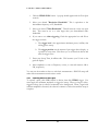
by simply clicking on the trace. Fine-tune a marker's placement using your
mouse wheel.
⇒ PEAK moves the marker to the highest amplitude signal on the graticule.
⇒ DELTA anchors the marker’s reference (e.g. 1R) at the marker’s current
position. Move the marker by left-clicking and/or using the mouse wheel to
make differential measurements relative to the reference.
⇒ UPDATE ON/OFF When Update is ON, the marker’s amplitude
updates each sweep. When OFF, the marker’s
amplitude does not update unless it is moved.
⇒ OFF turns the marker off and back to default
The marker sequence of
OFF, PEAK, DELTA
is good for reliable dBc
measurements.
settings.
⇒ MKR to CF sets CENTER FREQUENCY to the current marker position.
⇒ MKR to REF LVL sets the REFERENCE LEVEL to the current marker
position.
2.2.5
BANDWIDTH CONTROLS
⇒ Res BW: This controls the resolution bandwidth (RBW). For each span, a
range of resolution bandwidths may be used. The resolution bandwidth
controls the Intermediate Frequency (IF) bandpass filter.
o Resolution bandwidths are available from 0.1 Hz to 250 KHz,
typically in powers of 2. A 5 MHz RBW is also available for
limited functions.
o The SPAN (stop - start frequencies) will affect which RBWs are
available.
o The SPAN and RBW determine the number of data points in a
sweep, roughly 2.5 x SPAN/RBW.
⇒ Video BW: This controls the video bandwidth (VBW). After the signal has
been passed through the RBW filter, it is converted to an amplitude. This
amplitude is then filtered by the Video Bandwidth filter. This is
implemented as a simple “rectangle" averaging window.
o Video bandwidths are available from 0.1 Hz to 250 KHz,
typically in powers of 2. VBW must be equal to or less than
RBW.
7