1
13
3 axis controller user manual
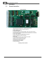
The controller is the headt of a positioning system. It perform the following tasks:
· Generate the direction signals and step frequencies to the drivers to move the motors at
the desired position.
· Activate the outputs.
· Wait a status at an input.
· Perform the timing between two command.
· Transmit informations about the position and the status.
· Acquire the Stop status.
· Acquire the Limits status.
· Seek the Home switch to put the axis in this position.
The actions above mentioned can be performed by comunicating, trhough the serial PC
line, with defined commands than will be executed by the controller in the sequence that
are been transmitted. In the controller there is a receive buffer that allow the same to
execute work of hours without interruptions. The communication handshake is managed
by the CTS and RTS control signals.
4.2
Communication
The communication with the controller is established with RS232: the line parameters are:
Bit:8
Stop bit: 1
Parity: None
Baud rate: 19200 bps.
The cable to use is a simple direct MF DB9.
The flow control signals are RTS and CTS. Note: in absence of those signals an
overwriting of the buffer can occur with severe consequence for the correct
excecution.
The RS 485 is optional and is reserved for future or custom usages.
4.3
Speed and acceleration
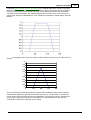
The speed, in a system composed by three axis is done with the following
formula:
here V is the speed and vx,vy, vx are the component speeds.The
controller calculate the component speeds for any axis to make the final desired speed that can
be set with the SVv; command where v is the speed in cm/s
The acceleration of a system is the variation of the velocity with the time, this parameter is set in
cm/s² in the controller.
The controller have two command for the setting of these parameters, read the
© 2002 Twintec