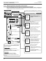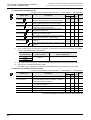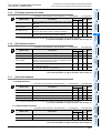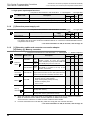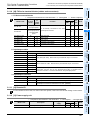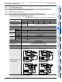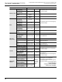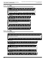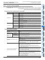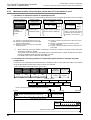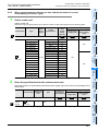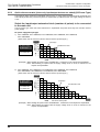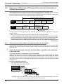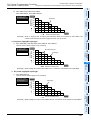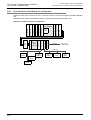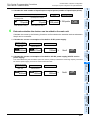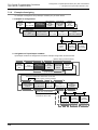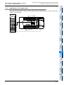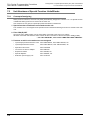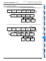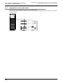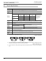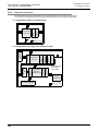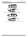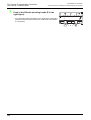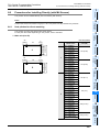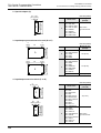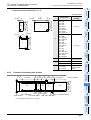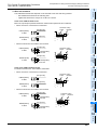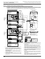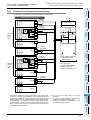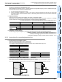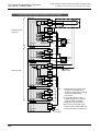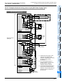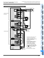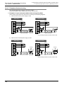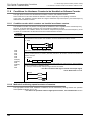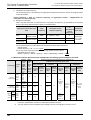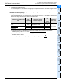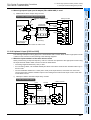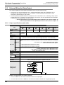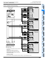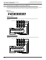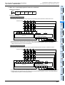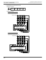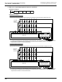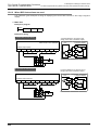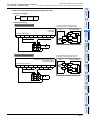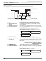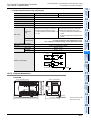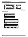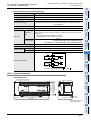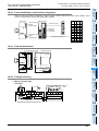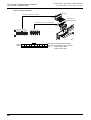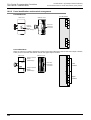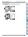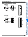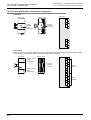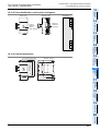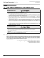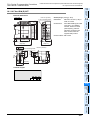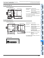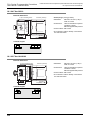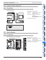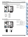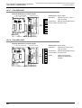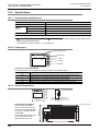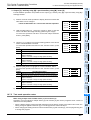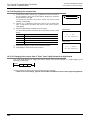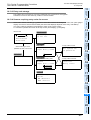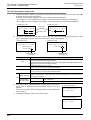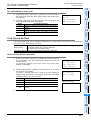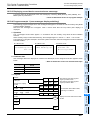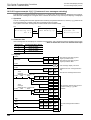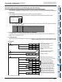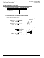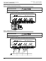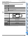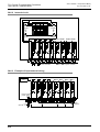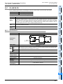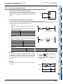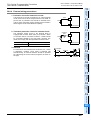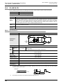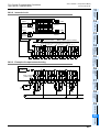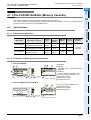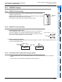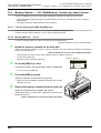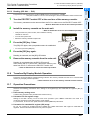
1
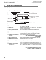
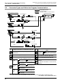
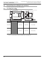
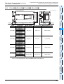
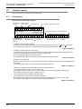
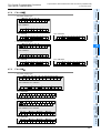
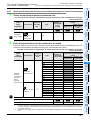
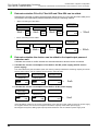
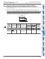
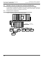
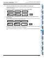
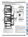
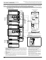
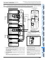
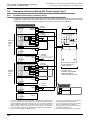
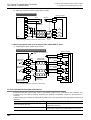
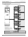
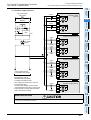
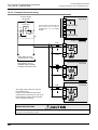
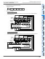
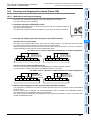
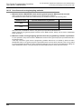
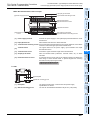
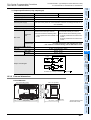
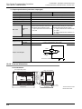
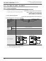
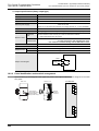
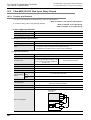
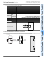
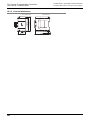
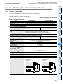
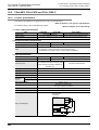
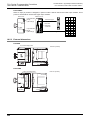
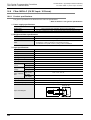
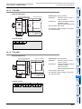
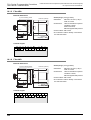
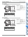
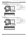
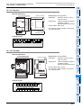
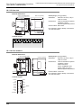
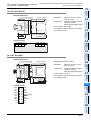
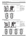
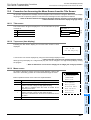
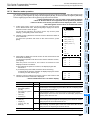
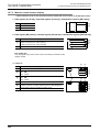
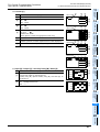
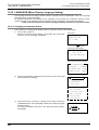
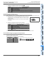
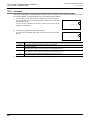
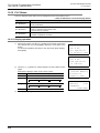
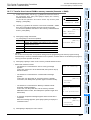
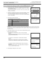
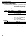
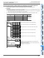
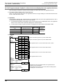
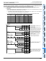
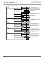
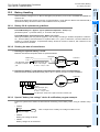
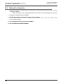
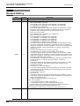
FX3U Series Programmable Controllers
13 Examples of Wiring for Various Uses
User’s Manual - Hardware Edition
13.2 Digital Switch [DSW Instructions (FNC72)/BIN Instructions (FNC19)]
2. Main unit + input/output powered extension unit/block
Example of program
M8000
DSW
X010
Y050
D100
K1
Examples of wiring
In the case of sink wiring
When the main unit and a transistor output (sink) type input/output powered extension unit/block are used
Digital
switch of
BCD
100
101
102
103
0.1A 50V
diode is
necessary.
S/S
0V
1
2
4
8
24V X010 X011 X012 X013
Main unit
*1
*2
COM 24+
X
Input/output powered extension unit
Output extension block
Transistor output (sink)
COM1 Y050 Y051 Y052 Y053
100 101 102 103
*1 To use the input terminal (X) of the input/output powered extension unit, wire the terminal as shown by the dotted line.
*2 The terminals in the shaded areas are provided on input/output powered extension units (ex.: FX2N-32ET).
Output extension blocks do not have the terminals.
In the case of source wiring
When the main unit and a transistor output (source) type input/output powered extension unit/block are used
Digital
switch of
BCD
100
101
102
103
0.1A 50V
diode is
necessary.
S/S
0V
1
2
4
8
24V X010 X011 X012 X013
Main unit
*1
*2
S/S 0V 24V
X
Input/output powered extension unit
Output extension block
Transistor output (source)
+V0 Y050 Y051 Y052 Y053
100 101 102 103
*1 To use the input terminal (X) of the input/output powered extension unit, wire the terminal as shown by the dotted line.
*2 The terminals in the shaded areas are provided on input/output powered extension units (ex.: FX2N-32ET-ESS/UL).
Output extension blocks do not have the terminals.
224