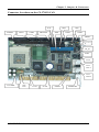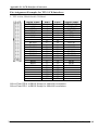
1
CJ370P/I (Pisa/Isa) Pentium III Half-Size CPU Card With VGA, Audio & Dual LAN User’s Manual Version 1.4b (C) CJB Computer Job Srl - www.cjb.it - [email protected] Copyright Notice This publication is protected by copyright and all rights are reserved. No part of it may be reproduced or transmitted by any means or in any form, without prior consent of the original manufacturer. The information in this document has been carefully checked and is believed to be accurate. However, the original manufacturer assumes no responsibility for any inaccuracies that may appear in this manual. In no event will the original manufacturer be liable for direct, indirect, special, exemplary, incidental, incidental or consequential damages resulting from any defect or omission in this manual, even if advised of possibility of such damages. The material contained herein is for informational purposes only. Acknowledgments Award is a registered trademark of Award Software International, Inc. S3 is a trademark of S3 Technologies Inc. IBM, PS/2 are trademarks of International Business Machines Corporation. Intel, PentiumIII and Celeron are registered trademarks of Intel Corporation. Microsoft Windows is a registered trademark of Microsoft Corporation. All other product names or trademarks are properties of their respective owners. C.J.B. Computer Job Srl Via Ghislandi, 24 - 25125 BRESCIA - Italy Phone.: +39030-3531883 Fax.: +39030-349557 Website: http://www.cjb.it E-mail: [email protected] ii CJ-370P/I-CAN User’s Manual 1.4b Contents Contents Chapter 1 Introduction .................................. 1 Checklist.................................................................................. 2 Description .............................................................................. 2 Features................................................................................... 4 Specifications .......................................................................... 6 Intelligence .............................................................................. 9 Chapter 2 Installation .................................. 11 CPU Installation ................................................................... 12 Memory Installation............................................................. 13 Jumpers on the CJ-370P/I-CAN ......................................... 13 Jumper Locations on the CJ-370P/I-CAN ............................. 14 JP5 ~ JP6: CPU Frequency Selector ...................................... 15 JP7 LCD PANEL Power Selection ........................................ 16 JP8: CMOS RAM Data .......................................................... 16 JP9 JP10: WatchDog Timer Period Selection........................ 17 JPCOM4: COM2 RS232/RS422/RS485 Selection ................ 17 Connectors on the CJ-370P/I-CAN .................................... 18 Connector Locations on the CJ-370P/I-CAN ........................ 19 Front Panel Connector............................................................ 20 CPU Fan Power Connector .................................................... 21 USB Connectors..................................................................... 21 EIDE Connectors.................................................................... 22 Floppy Drive Connector......................................................... 24 Parallel Port Connector .......................................................... 25 COM1 Serial Port................................................................... 26 COM2 Serial Port................................................................... 26 COM3 Serial Port................................................................... 27 COM4 Serial Port................................................................... 27 External PS2 Mouse Connector ............................................. 28 PS/2 Keyboard & Mouse Connector ...................................... 28 VGA Connector..................................................................... 29 IrDA Connector...................................................................... 29 ATX Power Connector........................................................... 30 LAN- RJ45 Connector ........................................................... 30 LAN LEDs ............................................................................. 30 CJ-370P/I-CAN User’s Manual 1.4b iii Contents AT Power P8 Connector ........................................................ 31 CD_IN Connectors................................................................. 31 Audio Connectors .................................................................. 32 Watchdog Timer Configuration ......................................... 32 Chapter 3 BIOS Configuration ................ 34 BIOS Introduction ............................................................... 35 Starting Setup......................................................................... 35 Using Setup............................................................................ 36 Getting Help........................................................................... 36 In Case of Problems ............................................................... 37 Main Menu ........................................................................... 38 Standard CMOS Features ........................................................... 38 Advanced BIOS Features ............................................................ 38 Advanced Chipset Features ......................................................... 38 Integrated Peripherals................................................................. 39 Power Management Setup........................................................... 39 PnP / PCI Configuration ............................................................. 39 PC Health Status ......................................................................... 39 Frequency/Voltage Control ......................................................... 39 Load Fail-Safe Defaults .............................................................. 39 Load Optimized Defaults............................................................. 39 Supervisor / User Password ........................................................ 39 Save & Exit Setup ........................................................................ 39 Exit Without Save ........................................................................ 39 Standard CMOS Setup........................................................ 40 Primary HDDs / Secondary HDDs ........................................ 42 Drive A / Drive B................................................................... 44 Video...................................................................................... 44 Halt On................................................................................... 44 Advanced BIOS Features .................................................... 45 Virus Warning........................................................................ 45 CPU Internal Cache/External Cache...................................... 46 CPU L2 Cache ECC Checking .............................................. 46 Processor Number Feature..................................................... 46 Quick Power On Self Test ..................................................... 46 First/Second/Third/Other Boot Device .................................. 46 Swap Floppy Drive ................................................................ 46 Boot Up Floppy Seek............................................................. 46 Boot Up NumLock Status...................................................... 47 Gate A20 Option .................................................................... 47 Typematic Rate Setting.......................................................... 47 iv CJ-370P/I-CAN User’s Manual 1.4b Contents Typematic Rate (Chars/Sec)................................................... 47 Typematic Delay (Msec)........................................................ 47 Security Option ...................................................................... 47 OS Select For DRAM > 64MB .............................................. 48 Video BIOS Shadow .............................................................. 48 C8000 - CBFFF Shadow/DC000 - DFFFF Shadow .............. 48 Advanced Chipset Features................................................. 49 DRAM Settings ...................................................................... 49 DRAM Timing By SPD ......................................................... 50 DRAM Clock . ....................................................................... 50 SDRAM Cycle Length ........................................................... 50 Memory Hole ......................................................................... 50 System BIOS Cacheable ........................................................ 50 Video RAM Cacheable .......................................................... 50 Frame Buffer Size .................................................................. 51 AGP Aperture Size................................................................. 51 Panel Type.............................................................................. 51 Boot Device Select ................................................................. 52 Power-Supply Type................................................................ 52 OnChip USB .......................................................................... 52 USB Keyboard Support.......................................................... 52 USB Mouse Support............................................................... 52 OnChip Sound........................................................................ 53 Integrated Peripherals ......................................................... 54 OnChip IDE Channel 0 .......................................................... 54 OnChip IDE Channel 1 ......................................................... 54 IDE Prefetch Mode................................................................. 55 Primary/Secondary Master/Slave PIO.................................... 55 Primary/Secondary Master/Slave UDMA.............................. 55 Init Display First..................................................................... 55 IDE HDD Block Mode........................................................... 55 Onboard FDC Controller........................................................ 55 Onboard Serial Port 1/Port 2 .................................................. 56 UART 2 Mode........................................................................ 56 IR Function Duplex................................................................ 56 TX,RX inverting enable ......................................................... 56 Onboard Parallel Port ............................................................. 56 Onboard Parallel Port Mode................................................... 56 ECP Mode Use DMA............................................................. 56 EPP Mode Select.................................................................... 57 Onboard Serial Port 3/Port 4 .................................................. 57 CJ-370P/I-CAN User’s Manual 1.4b v Contents Serial Port 3/Port 4 Use IRQ.................................................. 57 Power Management Setup .................................................. 58 ACPI Function ....................................................................... 58 Power Management ............................................................... 58 PM Control by APM.............................................................. 59 Video Off Option ................................................................... 59 Video Off Method.................................................................. 60 MODEM Use IRQ ................................................................. 60 PM Events.............................................................................. 60 VGA ............................................................................................. 60 LPT & COM ................................................................................ 60 HDD & FDD ............................................................................... 60 PCI Master .................................................................................. 60 Modem Ring Resume ................................................................... 60 RTC Alarm Resume ..................................................................... 60 IRQs Activity Monitoring ............................................................ 61 PnP/PCI Configuration Setup ............................................ 62 PNP OS Installed ................................................................... 62 Reset Configuration Data....................................................... 62 Resource controlled by .......................................................... 62 IRQ Resources ....................................................................... 63 DMA Resources..................................................................... 63 PCI/VGA Palette Snoop ........................................................ 63 Assign IRQ For VGA/USB ................................................... 63 PC Health Status .................................................................. 64 Current CPU Temperature ..................................................... 64 Current System Temp. ........................................................... 64 Current CPU FAN Speed....................................................... 64 Vcore/2.5V/3.3V/5V/12V Voltages....................................... 64 Frequency/Voltage Control................................................. 65 Auto Detect DIMM/PCI CLK ............................................... 65 Spread Spectrum Modulated.................................................. 65 CPU Host Clock (CPU/PCI).................................................. 65 Load Fail-Safe Defaults ....................................................... 66 Load Optimized Defaults .................................................... 66 Supervisor/User Password Setting ..................................... 67 Exit Selecting ........................................................................ 68 Save & Exit Setup................................................................. 68 Exit Without Saving............................................................... 68 Appendix .......................................................... 69 vi CJ-370P/I-CAN User’s Manual 1.4b Contents A. I/O Port Address Map..................................................... 70 B. Interrupt Request Lines (IRQ)....................................... 71 C. POST Beep ....................................................................... 72 D. LCD Connector............................................................... 73 CJ-370P/I-CAN User’s Manual 1.4b vii Contents This page was intentionally left free CJ-370P/I-CAN User’s Manual 1.4b viii Chapter 1 Introduction 1 Introduction This manual will give you information on the CJ-370P/I-CAN SBC card. The topics covered in this chapter are as follows: ♦ Checklist ♦ Description ♦ Features ♦ Specifications ♦ Intelligence CJ-370P/I-CAN User’s Manual 1.4b 1 Chapter 1 Introduction Checklist Please check that your package is complete and contains the items below. If you discover damaged or missing items, please contact your dealer. ü The CJ-370P/I-CAN Industrial SBC Card ü 1 ATA66/100 IDE Ribbon Cable ü 1 Floppy Ribbon Cable ü 1 Serial Port Ribbon Cable and 1 Parallel Port attached to a Mounting Bracket ü 1 Serial Port Ribbon Cable attached to a Mounting Bracket ü 1 CD Disc Containing S3 VGA Drivers, RealTek 8100B LAN Driver, VIA chipset drivers, BIOS Update Utility and this User’s manual. ü PS/2 Keyboard and Mouse 1-to-2 Y-cable Description The CJ-370P/I-CAN is a Pentium III Industrial single board computer card based on VIA 8606 chipset and is fully designed for harsh industrial environment. It features one Socket370, that is compatible with Intel FC-PGA package Pentium III processor. This card accommodates up to 512MB of PC133 SDRAM memory. The CJ-370P/I-CAN is a high integration CPU. Two RealTek 8100B Fast Ethernet Controllers, ALC201A Audio codec and S3 4X AGP Video controller are integrated into the system. The high-integration design prevents the system compatibility issues and increases the PCI add-on cards scalability. This makes CJ-370P/I-CAN an ideal SBC card for Automation, Embedded control, Thin client as well as other industrial applications. CJ-370P/I-CAN provides the most complete features needed for system operation. These include 10/100 TX LAN adapter, Ultra DMA 66/100 IDE drive controllers, high performance serial ports, enhanced parallel port, and the most updated BIOS. Two USB ports, one 2 CJ-370P/I-CAN User’s Manual 1.4b Chapter 1 Introduction RS232/422/485 port and a programmable watchdog timer are available on-board. The CPU card also provides a LCD panel interface for connecting a Direct-Drive LCD Panel. The LVDS interface is also reserved to support latest LVDS Panel. What’s more, the VIA Twister-T chipset on-board card incorporates the latest microprocessor technology to provide the increased bandwidth needed to operate your system bus at speeds up to 133 MHz. The CJ-370P/I-CAN comes with VIA integrated hardware monitoring device that monitors system and CPU temperature, voltages of all system power rails, and CPU fan speeds to prevent system crashes by warning the user of adverted conditions. The power management feature provides power savings by slowing down the CPU clock, turning off the monitor screen and stopping the HDD spindle motor. The CJ-370P/I boards are THE SAME BOARD with two passive bus interfaces: the CJ-370P has PISA (PCI-ISA) bus interface, while the CJ-370I has ISAbus interface. Nevertheless, the two boards are 100% identical. This manual so refers to any of the two CJ-370 versions. However, remember that only the PISA version will be able to drive PCIbus add-on cards (using suitable PISA passive backplanes). CJ-370P/I-CAN User’s Manual 1.4b 3 Chapter 1 Introduction Features 4 • High-Speed Processors: Supports Intel FC-PGA Pentium III and Celeron Processor from 500 to 1.4GHz or above with 66/100/133MHz FSB Speed. • Low-Power Processors: Fully support Intel Coppermine, Tualatin and VIA C3 processor. Both Intel Tualatin and VIA C3 CPU adapt 0.13 process and operate at lower voltage. This provide the CJ-370P/I-CAN system as a low power consumption system. • VIA Twister-T AGPset: Features VIA Twsiter-T AGPset with I/O subsystems and front-side bus (FSB) platform, which boosts the traditional 66/100MHz internal bus speed to 133MHz. • PC133 Memory Support: Equipped with one DIMM sockets to support Intel PC100/PC133-compliant SDRAM (8, 16, 32, 64, 128MB, 256MB or 512MB). Up to 512MB of PC133 SDRAM system memory. • Flexible Memory Speed: The System memory bus speed can be equal to CPU FSB and –33MHz or +33MHz of FSB Speed. This gives users more flexibility to choose different memory technology. • ECC function support: Processor front-side bus (FSB) and Memory subsystem support ECC function for Fault-tolerant application. • 10/100Base-T Fast Ethernet: Features Two RealTek Fast Ethernet controllers that boost network performance, increase the networking bandwidth and reliability, enhanced system manageability and offers the proven compatibility. • Integrated S3 Savage4 2D/3D/Video Accelerator: The VIA Twister-T chipset integrated S3 Savage4 2D/3D/Video accelerator in Shared Memory Architecture (SMA). The 2D hardware accelerator, 3D rendering engine, MPEG-2/DVD decoder are integrated. The frame-buffer size can be adjust in BIOS setup and stored in CMOS. • Direct Interface to broad range of LCDs: Two LCD connectors support wide range of LCD panels, includes SXGA+ TFT color panel with 9-, 12-, 18- (both 1 pixel/clock and 2 pixels/clock), and 24-bit; VGA, SVGA, XGA dual-scan/single scan color panels with 8-bit, 16-bit CJ-370P/I-CAN User’s Manual 1.4b Chapter 1 Introduction and 24-bit interface; Enhanced STN hardware with 256 gray scale support and advanced frame rate control to provide 16M colors. The latest LVDS panel is also supported. • PCI Bus Master IDE Controller: Two enhanced IDE channels for up to four devices, support PIO Mode 3/4 or Ultra DMA/33/66 IDE Hard Disk, ATAPI CD-ROM, LS120 drive and DOM. The Secondary IDE is interfaced with a 44-pin 2mm pitch connector. It supports 2.5” HDD directly as well as 44-pin DOM without additional power connector. • Watch-Dog Timer: 4 level programmable watchdog timer, from 10-80 seconds. • Super Multi-I/O: Provides four high-speed UART compatible serial ports and one parallel port with SPP, EPP and ECP capabilities. The COM4 can be configured as RS232, RS-422 or RS485 interface. • IrDA: Support an optional infrared port module for wireless interface. • Concurrent PCI: Allows multiple PCI transfers from PCI master buses and AGP bus to memory to CPU. • Hardware Monitoring: Features VIA integrated Hardware Monitor to monitor all the power rails as well as CPU and board temperature. • Enhanced ACPI: Features a programmable BIOS (Flash EEPROM), Offering enhanced ACPI for Windows compatibility and auto-detection of most devices for virtually automatic setup. • 3D Enhanced AC97 Audio Codec: ALC201A features the high S/N ratio (> 90dB) and 3D enhancement. Two pinheaders allow user to wire CD_IN, Line-out and Mic signals to Front panel or bridge board. Complete OS drivers and Applications are bundled in Driver CD. CJ-370P/I-CAN User’s Manual 1.4b 5 Chapter 1 Introduction Specifications • Processor Socket: Socket370 for FC-PGA and FC-PGA2 CPU. • Processor: § Intel FC-PGA/FC-PGA2 Pentium III 600/650/667/750/800/850/866/933/1000/1113MHz and above (100MHz FSB or 133 MHz FSB) § Intel Celeron Processor 533/566/600/633/337/700/733/766/800/850/900/1000/1200 MHz and above (66MHz FSB or 100MHz FSB) § VIA C3 Processor 700/766/800/866/933 MHz and above (66M/100M/133MHz FSB) § Intel latest Tualatin and VIA C3 low power processors are supported. • Chipset: VIA Twister-T and 82686B with PCI EIDE, Super-IO and RTC built-in. • Secondary Cache: 512K(Tualatin), 256K(Coopermine) or 128KB(Celeron) L2 cache integrated in CPU and runs on CPU core frequency. • Memory Sockets: One 168-pin DIMM socket Memory types: 3.3V SDRAM (Synchronous DRAM) support 8MB to 512MB memory capacity. Both ECC and non-ECC Memory module are supported. NOTE: Only SDRAM modules that support SPD (Serial Presence Detect) should be use. Use PC133 modules when running 133MHz Memory bus speed and use PC133/PC100 modules when running133MHz memory bus speed. • BIOS: Award BIOS, PnP support § FLASH EEPROM (256KB) for BIOS update § Enhanced ACPI BIOS and DMI 2.0 § ISA Plug and Play (PnP) extension § Power management § Anti-Boot Virus • DMI BIOS Support: Desktop Management Interface (DMI) allows users to download system hardware-level information such as CPU type, CPU speed, internal/external frequencies and memory size. 6 CJ-370P/I-CAN User’s Manual 1.4b Chapter 1 Introduction • Multi I/O: § Parallel Port: One high-speed parallel port, SPP/EPP/ECP mode. § Serial Port: Four 16550 UART compatible ports with COM1, COM2 and COM3 as RS232. COM4 can be RS232/422/485. § IrDA Interface: Pin-header connector for the optional IrDA external connector • Enhanced IDE: Two EIDE interfaces for up to four devices, support PIO Mode 3/4 or Ultra DMA/33/66 IDE Hard Disk, ATAPI CD-ROM, DOM and LS-120 drive • FDD Interface: Two floppy drives (360KB, 720KB, 1.2MB, 1.44MB, 2.88MB) • S3 Savage4 : VIA 8606 integrates S3 Savage4 2D/3D/Video accelerator. § Optimized Shared Memory Architecture (SMA). § 8 / 16 / 32 MB frame buffer using system memory, selected by user through BIOS setup. § High quality DVD video playback. § 2D/3D resolutions up to 1920x1440. § Motion compensation for full speed DVD playback and MPEG-2 video textures. § Extensive LCD Support, includes 36-bit DSTN/TFT flat panel interface with 256 gray shade support, one 110 MHz LVDS interface, Support for all resolutions up to 1600x1200, Panel power sequencing, Hardware Suspend/Standby control. § Drivers for major operating systems and APIs: [Windows 9x, Windows NT 4.0, Windows 2000, Direct3D, DirectDraw and DirectShow, OpenGL ICD for Windows 9x, NT, and 2000] • USB Interface: Two USB ports interfaced with one 2x5 pinheader, compliant with USB Specification Rev. 1.1 and support USB Hot-Plug function. • ATX Power Supply support: § On-board 4-pin ATX power supply header (requires the passive backplane supports ATX power supply) CJ-370P/I-CAN User’s Manual 1.4b 7 Chapter 1 Introduction • § On-board power button header for Soft power off, i.e. front panel turn off system power. § Support Win95 and Win98 shutdown automatically turn off the system power. Hardware Monitor System: § PC Health Monitoring ASIC supports system power voltages, FAN speed and system temperatures monitoring. § One FAN connector and one thermal couple header reserved for chassis FAN and temperature monitoring. • Watchdog Timer: § Read I/O port 0443H to enable watchdog. § Read I/O port 043H to disable watchdog. § 10s, 20s, 30s and 80s timeout period selectable. • Green unction: Power management via BIOS, activated through mouse/keyboard movement or SMI button • Keyboard and Mouse Connectors: One 6-pin mini-DIN connector is located on the mounting bracket for easy connection to a keyboard and PS/2 mouse. A 5-pin on-board pin-header is also available to support PS2 mouse. • PISA Compliance: Fully compliant to PISA Rev 1.7 specification. • Environmental and Mechanical: § § § § 8 Power Supply: 5A@ +5v typical; 300mA@ +12v typical 100mA@ -12V typical; 200mA@ +5VSTB (Option) Temperature: 0°C to 60°C operating; -40°C to 70°C storage Humidity: 5% to 95% Dimensions: 7.28"(L) x 5.0"(W) or 185mm (L) x 127mm (W) CJ-370P/I-CAN User’s Manual 1.4b Chapter 1 Introduction Intelligence • Support 133MHz CPU and SDRAM: The VIA 8606 Twister-T chipset boosts the CPU FSB bus and Memory interface speed to 133MHz. • Flexible Memory Speed: The Memory bus speed can be same with CPU FSB speed (Default). It is also allow users to run 133MHz PC133 memory while CPU runs on 100MHz FSB. Or Boost CPU FSB speed to 133MHz while use low cost PC100 zMemory module. No compromise and better flexibility. • High-Integrated 2D/3D/VIDEO Accelerator: The built-in S3 Savage4 VGA chip support AGP 4X mode with Sideband Addressing and AGP Texturing (Execute mode) to realize all the benefits of AGP. The Share Memory Architecture (SMA) allows user to decide how many main memory size will be allocated for video graphic buffer. This saves system cost yet reserve room for applications which require large frame buffer size. • Dual LAN Design: Two 10/100M Ethernet provide aggregated bandwidth can be up to 400Mbps while two ports working on full-duplex 100-BaseT. The dual port design fulfill the needs of emerging Internet appliances, NAS as well as servers applications. . The drivers for most popular Operation systems and NOS have been validated and proved the compatibility. It also supports latest network standards and protocols like speed auto-negotiation between 10Base-T and 100Base-T, half/full duplex (IEEE8023.3u), flow-control (IEEE8023X), VLAN (IEEE802.3Q), Priority packet(IEEE802.3P) and etc. The multiprotocols support ensures the best interoperability. • Two EIDE channels: Two IDE channels designed in the small PISA form factor. The Secondary IDE connector is designed with 44-pin 2mm pitch connector. This allow user connector to a 2.5” HDD directly with out any bridge board. DOM users can choose 44-pin DOM for small package and save power cable connector. CJ-370P/I-CAN User’s Manual 1.4b 9 Chapter 1 Introduction This page is intentionally left blank. 10 CJ-370P/I-CAN User’s Manual 1.4b 2 Jumpers & Connectors This chapter provides information on how to use the jumpers and connectors on the CJ-370P/I-CAN in order to set up a workable system. The topics covered are: CPU Installation .....................................................................12 Memory Installation ...............................................................13 Jumpers on the CJ-370P/I-CAN ............................................ 13 Connectors on the CJ-370P/I-CAN ....................................... 18 Watchdog Timer Configuration..............................................32 11 CJ-370P/I-CAN User’s Manual 1.4b Chapter 2 Jumpers & Connectors CPU Installation The CJ-370P/I-CAN Industrial SBC Card has a 370-pin ZIF socket for Pentium II/III-processors and Celeron with FC-PAG and PPGA (Plastic Pin Grid Array) package. Before installing the processor into the Socket, ensure that the CPU fan is installed first. Without a fan circulating air on the CPU, the CPU can overheat and cause damage to both CPU and SBC card. To Install a CPU, first turn off your system and remove its cover. Locate the ZIP socket and open it by first pulling the lever sideways away from the socket then upwards to a 90-degree right angle. Insert the CPU with the correct orientation. Use the notched corner of the CPU with the white dot as your guide. The white dot should point towards the end of the lever. Notice that there is a blank area where one hole is missing from that corner of the square array of pin holds. Because the CPU has a corner pin for three of the four corners, the CPU will only fit in one orientation. With the added weight of the CPU fan, no force is required to insert the CPU. Once completely inserted, hold down on the fan and close the socket lever. To disassembly the processor, simply pull the lever sideways away from the socket then upward to a 90-degree right angle. You can take the CPU out from the socket without help of any tool. WARNING!: If no FAN circulating Air on the CPU, the processor might been overheated and damage both CPU and SBC components. 12 CJ-370P/I-CAN User’s Manual 1.4b Chapter 2 Jumpers & Connectors Memory Installation The CJ-370P/I-CAN Industrial CPU Card has one 168-pin DIMM socket for a maximum total memory of 512MB SDRAM. The memory modules can come in sizes of 16MB, 32MB, 64MB, 128MB 256MB and 512MB SDRAM. NOTE: Use SDRAM modules with PC133 specification when running 133Mhz Memory bus speed. With 100MHz Memory bus speed, SDRAM modules meet PC133 or PC100 specification can be used. Jumpers on the CJ-370P/I-CAN The jumpers on the CJ-370P/I-CAN allow you to configure your SBC card according to the needs of your applications. If you have doubts about the best jumper configuration for your needs, contact your dealer or sales representative. The following table lists the jumpers on CJ-370P/I-CAN and their respective functions. Jumper Locations on the CJ-370P/I-CAN .............................14 JP5 ~ 6 : CPU Frequency Selector .........................................15 JP7 : LCD Panel Power Selection .........................................16 JP8 : Clear CMOS RAM Data................................................16 JP12~13 : WatchDog Timer Period Selection....................... 17 JCOM4 : COM4 RS232/RS422/RS485 Selection..................17 CJ-370P/I-CAN User’s Manual 1.4b 13 Chapter 2 Jumpers & Connectors Jumper Locations on the CJ-370P/I-CAN JCOM4 1 1 JP7 JP5 JP6 JP10 JP8 JP9 P10 The ISAbus version is the same, except the passive-bus connector at the bottom 14 CJ-370P/I-CAN User’s Manual 1.4b Chapter 2 Jumpers & Connectors JP5 ~ JP6: CPU Frequency Selector JP5 and JP6 allow users to select the CPU FSB speed. It can be 66MHz, 100MHz or 133MHz. Most of Pentium III CPU runs on 100MHz or 133MHz FSB. However, Some Celeron CPUs run on 66MHz or 100MHz. User should select the correct FSB speed to make their CPU run on correct speed and ensure the system runs stably. JP5~JP6 1 1 1 Setting Function JP5: Pin 1-2 Short JP6: Pin 1-2 Short 133MHz CPU FSB JP5: Pin 2-3 Short JP6: Pin 1-2 Short 100MHz CPU FSB JP5: Pin 2-3 Short JP6: Pin 2-3 Short 66MHz CPU FSB 1 1 1 The Core Frequency to Bus clock ratio of most of Intel Pentium III is locked. Users do not require to change Jumpers JP5~6. These Jumpers are reserved for Internal test purpose only. NOTE: The BIOS setup Default value will program the SDRAM Memory bus runs on same clock speed with CPU FSB, which is decided by JP5~6. However, The CPU clock speed showed on the Boot message is not necessarily present the Memory Bus speed. User’s may program the BIOS setup to run Memory bus in different speed. Overclocking your processor and SDRAM module is not recommended. There is no guarantee for any over-speed operation. CJ-370P/I-CAN User’s Manual 1.4b 15 Chapter 2 Jumpers & Connectors JP7 LCD PANEL Power Selection JP7 can be used to select the Panel LCD supply power, +3V or +5V. The default setting is on +3V. User need to check the LCD panel spec and adjust this jumper and make Panel work in specified power rail. +3V +5 JP7 JP7 JP8: CMOS RAM Data This 3-pin Jumper allows the user to disconnect the built-in 3V battery power to clear the information stored in the CMOS RAM. To clear the CMOS data: (1) Turn off the system power, (2) Remove Jumper cap from pin1&2, (3) Short the pin2 and pin3 for three seconds, (4) Put Jumper cap back to pin1& 2. (5) Turn on your computer, (6) Hold Down <Delete> during bootup and enter BIOS setup to enter your preferences. JP8 Setting Pin 1-2 Short/Closed Pin 2-3 Short/Closed 16 Function Normal Operation (default) Clear CMOS Content CJ-370P/I-CAN User’s Manual 1.4b Chapter 2 Jumpers & Connectors JP9 JP10: WatchDog Timer Period Selection The WatchDog Timer time-out period can be set 10 sec, 20 sec, 30 sec and 80 sec. The following table describes the jumper settings for the period. JP9 JP10 Time-out Period 10 Sec 20 Sec 30 Sec 80 Sec JPCOM4: COM2 RS232/RS422/RS485 Selection The COM4 port can be configured to operate with external devices on different interface mode. They are RS-232, RS-422 and RS485. JPCOM4. The following table describes how to configure the COM4 interface. JPCOM4 I/F TYPE RS-232 1 17 RS-422 1 17 RS-485 1 CJ-370P/I-CAN User’s Manual 1.4b 17 17 Chapter 2 Jumpers & Connectors Connectors on the CJ-370P/I-CAN The connectors on the CJ-370P/I-CAN allow to connect external devices such as keyboard, floppy disk drives, hard disk drives, printers, etc. The following table lists the connectors on CJ-370P/I-CAN and their respective page number. Front Panel Connector ........................................................... 20 CPU Fans Power Connector .................................................. 21 USB Connectors .................................................................... 21 EIDE Connectors ................................................................... 22 Floppy Drive Connector ........................................................ 24 Parallel Port Connector.......................................................... 25 COM1 Serial Port .................................................................. 26 COM2 Serial Port .................................................................. 26 COM3 Serial Port .................................................................. 27 COM4 Serial Port .................................................................. 27 External PS2 Mouse Connector ............................................. 28 PS/2 Keyboard & Mouse Connector...................................... 28 VGA Connector ..................................................................... 29 Opto-CAN & CANbus Connectors ....................................... 29 ATX Power Connector .......................................................... 30 LAN- RJ45 Connectors ......................................................... 30 LAN LEDs............................................................................. 30 AT Power P8 Connectors ...................................................... 31 CD_IN Connector .................................................................. 31 Audio Connector .................................................................... 32 LCD Connector ..................................................... Appendix A 18 CJ-370P/I-CAN User’s Manual 1.4b Chapter 2 Jumpers & Connectors Connector Locations on the CJ-370P/I-CAN LCD FLOPPY COM1 COM2 PRINTER IDE1 IDE2 USB COM3 COM4 FRONT Opto-CAN & CAN A CD_IN Audio VGA LAN Port A LAN Port B ATX PWR CPU FAN AT P8 CJ-370P/I-CAN User’s Manual 1.4b PC104 PS2MS PS2KB+MS 19 Chapter 2 Jumpers & Connectors Front Panel Connector The front panel of the case has a control panel which provides light indication of the computer activities and switches to change the computer status. 1 7 RESET HDD PWR PWR LED LED BTN Ø RESET Switch The reset switch allows the user to reset the system without turning the main power switch Off and then On. Orientation is not required when making a connection to this header. 1 Ø Reset RESET Pin # Signal Name 1 2 Reset Ground IDE Hard Disk LED Connector This connector connects to the hard drive activity LED on control panel. This LED will flash when the HDD is being accessed. 1 IDE LED IDE LED Pin # Signal Name 3 4 IDE_ACT Ground Ø Power-ON LED Connector The Power LED provide and interface to wire the system power on signal to front panel 1 20 PWR LED IDE LED Pin # Signal Name 5 6 +5V Ground CJ-370P/I-CAN User’s Manual 1.4b Chapter 2 Jumpers & Connectors Ø ATX Power ON/OFF Button This 2-pin connector acts as the “Power Supply On/Off Switch” on the SBC card. When pressed, the switch will force the SBC card to power on. When pressed again, it will force the SBC card to power off. 1 PWR BTN Pin # Signal Name 7 8 PWR-BTN GND Power Button CPU Fan Power Connector This is a 3-pin header for the CPU fan. The fan must be a 12V fan. 1 2 3 Pin # Signal Name 1 2 3 Rotation +12V Ground USB Connectors The following table shows the pin outs of the USB connectors. 6 7 8 9 10 1 2 3 4 5 USB1 Pin# USB0 Pin # Signal Name 10 9 8 7 6 1 2 3 4 5 +5V USBUSB+ Ground N.C. CJ-370P/I-CAN User’s Manual 1.4b 21 Chapter 2 Jumpers & Connectors EIDE Connectors Primary IDE Connector Signal Name Pin # Reset IDE Host data 7 Host data 6 Host data 5 Host data 4 Host data 3 Host data 2 Host data 1 Host data 0 Ground DRQ0 Host IOW Host IOR IOCHRDY DACK0 IRQ14 Address 1 Address 0 Chip select 0 Activity 22 1 3 5 7 9 11 13 15 17 19 21 23 25 27 29 31 33 35 37 39 Pin # Signal Name 2 4 6 8 10 12 14 16 18 20 22 24 26 28 30 32 34 36 38 40 Ground Host data 8 Host data 9 Host data 10 Host data 11 Host data 12 Host data 13 Host data 14 Host data 15 Key Ground Ground Ground Host ALE Ground No connect No connect Address 2 Chip select 1 Ground CJ-370P/I-CAN User’s Manual 1.4b Chapter 2 Jumpers & Connectors Secondary IDE Connector Signal Name Pin # Pin # Reset IDE Host data 7 Host data 6 Host data 5 Host data 4 Host data 3 Host data 2 Host data 1 Host data 0 Ground DRQ1 Host IOW Host IOR IOCHRDY DACK1 IRQ15 Address 1 Address 0 Chip select 0 Activity +5V Ground CJ-370P/I-CAN User’s Manual 1.4b 1 3 5 7 9 11 13 15 17 19 21 23 25 27 29 31 33 35 37 39 41 43 2 4 6 8 10 12 14 16 18 20 22 24 26 28 30 32 34 36 38 40 42 44 Signal Name Ground Host data 8 Host data 9 Host data 10 Host data 11 Host data 12 Host data 13 Host data 14 Host data 15 Key Ground Ground Ground Host ALE Ground No connect No connect Address 2 Chip select 1 Ground +5V No connect 23 Chapter 2 Jumpers & Connectors Floppy Drive Connector Floppy connector is a 34-pin header and will support up to 2.88MB floppy drives. 24 Signal Name Pin # Pin # Signal Name Ground Ground Ground Ground Ground Ground Ground Ground Ground Ground Ground Ground Ground Ground Ground Ground Ground 1 3 5 7 9 11 13 15 17 19 21 23 25 27 29 31 33 2 4 6 8 10 12 14 16 18 20 22 24 26 28 30 32 34 RM/LC No connect No connect Index Motor enable 0 Drive select 1 Drive select 0 Motor enable 1 Direction Step Write data Write gate Track 00 Write protect Read data Side 1 select Diskette change CJ-370P/I-CAN User’s Manual 1.4b Chapter 2 Jumpers & Connectors Parallel Port Connector The following table describes the pin out assignments of this connector. Signal Name Pin # Pin # Signal Name Line printer strobe PD0, parallel data 0 PD1, parallel data 1 PD2, parallel data 2 PD3, parallel data 3 PD4, parallel data 4 PD5, parallel data 5 PD6, parallel data 6 PD7, parallel data 7 ACK, acknowledge Busy Paper empty Select 1 2 3 4 5 6 7 8 9 10 11 12 13 14 15 16 17 18 19 20 21 22 23 24 25 N/A AutoFeed Error Initialize Select Ground Ground Ground Ground Ground Ground Ground Ground N/A CJ-370P/I-CAN User’s Manual 1.4b 25 Chapter 2 Jumpers & Connectors COM1 Serial Port COM1, a 10-pin header connector , is the onboard COM1 serial port of the CJ-370P/I-CAN . The following table shows its pin assignments. 9 1 Pin # Signal Name 1 2 3 4 5 6 7 8 9 10 DCD, Data carrier detect RXD, Receive data TXD, Transmit data DTR, Data terminal ready GND, ground DSR, Data set ready RTS, Request to send CTS, Clear to send RI, Ring indicator N.C. COM2 Serial Port COM2, a 10-pin header connector , is the onboard COM2 serial port of the CJ-370P/I-CAN .The table shows its pin assignments while it is configured as RS-232 interface. 9 26 1 Pin # Signal Name 1 2 3 4 5 6 7 8 9 10 DCD, Data carrier detect RXD, Receive data TXD, Transmit data DTR, Data terminal ready GND, ground DSR, Data set ready RTS, Request to send CTS, Clear to send RI, Ring indicator N.C. CJ-370P/I-CAN User’s Manual 1.4b Chapter 2 Jumpers & Connectors COM3 Serial Port COM3, a 10-pin header connector , is the onboard COM3 serial port of the CJ-370P/I-CAN. The table shows its pin assignments while it is configured as RS-232 interface. 9 1 Pin # Signal Name 1 2 3 4 5 6 7 8 9 10 DCD, Data carrier detect RXD, Receive data TXD, Transmit data DTR, Data terminal ready GND, ground DSR, Data set ready RTS, Request to send CTS, Clear to send RI, Ring indicator N.C. COM4 Serial Port COM4, a 10-pin header connector , is the onboard COM4 serial port of the CJ-370P/I-CAN. The table shows its pin assignments while it is configured as RS-232 and RS-422/485. For RS-485 connect TX+/RX+ and TX-/RX-. 9 1 Pin # RS232 Mode Signal Name RS422/RS485 Mode Signal Name 1 2 3 4 5 6 7 8 9 10 DCD, Data carrier detect RXD, Receive data TXD, Transmit data DTR, Data terminal ready GND, ground DSR, Data set ready RTS, Request to send CTS, Clear to send RI, Ring indicator N.C. TX- (422/485) TX+ (422/485) RX+ (422) RX- (422) GND N.C. N.C. N.C. N.C. N.C. Please notice that when set for RS422, the TX output can work only if you assert the RTS output of COM4. This is useful to manage multi-drop connected systems in RS422. See also Page 17 for JPCOM4 settings. CJ-370P/I-CAN User’s Manual 1.4b 27 Chapter 2 Jumpers & Connectors External PS2 Keyboard Connector (valid for both ISA & PISA from Rev 1.4) 1 Pin # Signal Name NOTICE: the assignment of the signals to the white JST header located inside the board (near the MiniDIN PS2 Mouse & Keyboard Connector) has been changed 1 PS2KBD clock for BOTH ISA & PISA versions 2 PS2KBD data of the CJ370, starting from the 3 NC. version 1.4. 4 GND If the sbc is a Rev1.4 or later, 5 +5V DO NOT connect a MOUSE to this connector, otherwise a short between KBD signals will happen and you may have a chance to damage the Mouse/KBD interface chipset. PS/2 Keyboard & Mouse Connector The following table describes the pin assignment of PS/2 Keyboard and Mouse connector, which is mount on button of bracket. To attach PS/2 Keyboard and mouse, users need to connect trough a PS/2 1-to-2 Y-cable and plug into this Mini-Din connector. All the P3BVLL SBC boards come with a Y-cable. Contact with your dealer if the Y-cable is missing. 28a Pin # Signal Name 1 2 3 4 5 6 Keyboard data Mouse data GND 5V Keyboard clock Mouse clock CJ-370P/I-CAN User’s Manual 1.4b Chapter 2 Jumpers & Connectors External PS2 Mouse Connector 1 Pin # Signal Name 1 2 3 4 PS2MS clock PS2MS data NC. GND 5 +5V PAGE VALID ONLY UP TO REV.1.3 OF THE BOARD PS/2 Keyboard & Mouse Connector The following table describes the pin assignment of PS/2 Keyboard and Mouse connector, which is mount on button of bracket. To attach PS/2 Keyboard and mouse, users need to connect trough a PS/2 1-to-2 Y-cable and plug into this Mini-Din connector. All the P3BVLL SBC boards come with a Y-cable. Contact with your dealer if the Y-cable is missing. 28b Pin # Signal Name 1 2 3 4 5 6 Keyboard data Mouse data GND 5V Keyboard clock Mouse clock CJ-370P/I-CAN User’s Manual 1.4b Chapter 2 Jumpers & Connectors VGA Connector The pin assignments of VGA CRT connector are as follows: Signal Name Pin Pin Signal Name Red Blue GND GND N.C. N.C. HSYNC NC 1 3 5 7 9 11 13 15 2 4 6 8 10 12 14 Green N.C. GND GND GND N.C. VSYNC Opto-CAN & CANbus Connectors This connector is used for connecting to external CANbus optoinsulator module. +5V RXin GND Pin # Signal Name TX RXout 1 5 +5V CAN TX RXin RXout GND CAN 2 3 4 Please ensure that a JUMPER is connecting pins 3+4 if the onboard 82C250 line interface driver/receiver is used; so you will use the onboard non-insulated interface, and you have to connect external devices to CANbus 3-pin connector (see below). This connector is used for connecting to external CANbus I/O modules. CAN-H CAN-L GND 1 2 3 CJ-370P/I-CAN User’s Manual 1.4b 1 2 3 CAN-H CAN-L CAN-GND 29 Chapter 2 Jumpers & Connectors ATX Power Connector This is a four-pin connector to support the ATX power and corresponding back-plane. When your back-plane is configured to perform ATX power supply Soft-on/off function, you have to connect the control signals and stand-by power on this connector to your backplane by a corresponding cable. 4 ATX-PWR Pin # Signal Name 1 2 3 4 PWR_GD 5V_SB (standby +5V) PS-ON (soft on/off) GND LAN- RJ45 Connector This connector is for the 10/100Mbps Ethernet capability of the CPU card. The figure below shows the pin out assignments of this connector and its corresponding input jack. TD+ (pin#1) TD- (pin#2) RD+ (pin#3) RD- (pin#5) LAN LEDs The LAN LEDs on top of bracket are to display the current network connection status. The green color LED on the left-hand side shows the link status and TX/RX activity. The Yellow color on the right-hand side indicates the operation mode, i.e. 10Base-T or 100Base-T. 30 LNK/ACT STATUS ON OFF FLASH Link Disconnected Packets TX/RX CJ-370P/I-CAN User’s Manual 1.4b Chapter 2 Jumpers & Connectors SPEED MODE ON OFF 100Base-T 10Base-T AT Power P8 Connector The following table describes the pin assignment of on-board AT Power P8 connector. This connector is for the applications which do not require a backplane. Users can connect it to an AT SPS P8 connector to supply the system power. The Power good signal will be generated by the circuit on the SBC card. Pin 1 is replace with +5V power to increase supply current. Pin # Signal Name 1 2 3 4 5 6 +5V +5V +12V -12V GND GND 1 CD_IN Connectors CD_INconnector is designed for wire the CD_ROM audio signals to the onboard Audio CODEC. (It's a LINE Input) 1 4 CJ-370P/I-CAN User’s Manual 1.4b CD-IN Pin # Signal Name 1 2 3 4 LINE-IN Left AGND AGND LINE-IN Right 31 Chapter 2 Jumpers & Connectors Audio Connectors AUDIO connector is designed for wire the Line-Out audio signals and the MIC Input signal to the on-board Audio CODEC. AUDIO Pin # Signal Name 1 2 3 4 5 Line-OUT_Left Line-OUT_Right AGND MIC Input AGND Watchdog Timer Configuration The function of the watchdog timer is to reset the system automatically and is defined at I/O port 0443H. To enable the watchdog timer and allow the system to reset, read I/O port 0443H. To disable the timer, read I/O port 043H for the system to stop the watchdog function. The timer has a tolerance of 20% for its intervals. The following describes how the timer should be programmed. Enabling Watchdog MOV DX, 0443H IN DX, AX Disabling Watchdog MOV DX, 043H OUT DX, AX 32 CJ-370P/I-CAN User’s Manual 1.4b Chapter 2 Jumpers & Connectors This page is intentionally blank. CJ-370P/I-CAN User’s Manual 1.4b 33 Chapter 3 BIOS Configuration 3 BIOS Configuration This chapter describes the different settings available in the Award BIOS that comes with the CJ-370P/I-CAN CPU card. The topics in this chapter are as follows: BIOS Introduction.................................................................. 35 Main Menu............................................................................. 38 Standard CMOS Setup........................................................... 40 Advanced BIOS Features....................................................... 45 Advanced Chipset Features.................................................... 49 Integrated Peripherals ............................................................ 54 Power Management Setup ..................................................... 58 PnP/PCI Configurations......................................................... 62 PC Health Status .................................................................... 64 Frequency/Voltage Control.................................................... 65 Load Fail-Safe Defaults ......................................................... 66 Load Optimized Defaults....................................................... 66 Supervisor/User Password Setting......................................... 67 Exit Selecting......................................................................... 68 34 CJ-370P/I-CAN User’s Manual 1.4b Chapter3 BIOS Configuration BIOS Introduction This Chapter discusses Award™ Setup program of the CJ-370P/I-CAN BIOS. The Setup program allows users to modify the basic system configuration. This special information is then stored in battery-backed RAM so that it retains the Setup information when the power is turned off. The AwardBIOS™ installed in CJ-370P/I-CAN is a custom version of an industry standard BIOS. This means that it supports Intel PentiumII/III and Celeron processors in a standard IBM-AT compatible input/output system. The BIOS provides critical low-level support for standard devices such as disk drives and serial and parallel ports. It also adds non-standard, features such as virus and password protection as well as special support for detailed fine-tuning of the chipset controlling the entire system. The rest of this chapter is intended to guide you through the process of configuring your system using Setup. Starting Setup The AwardBIOS™ is immediately activated when you first power on the computer. The BIOS reads the system information contained in the CMOS and begins the process of checking out the system and configuring it. When it finishes, the BIOS will seek an operating system on one of the disks and then launch and turn control over to the operating system. While the BIOS is in control, the Setup program can be activated in one of two ways: 1. By pressing <Del> immediately after switching the system on, or 2. by pressing the <Del> key when the following message appears briefly at the bottom of the screen during the POST (Power On Self-Test). Press DEL to enter SETUP. If the message disappears before you respond and you still wish to enter Setup, restart the system to try again by turning it OFF then ON or pressing the "RESET" button on the system case. You may also restart by simultaneously pressing <Ctrl>, <Alt>, and <Delete> keys. If you do not press the keys at the correct time and the system does not boot, an error message will be displayed and you will again be asked to... CJ-370P/I-CAN User’s Manual 1.4b 35 Chapter 3 BIOS Configuration PRESS F1 TO CONTINUE, DEL TO ENTER SETUP Using Setup In general, you use the arrow keys to highlight items, press <Enter> to select, use the PageUp and PageDown keys to change entries, press <F1> for help and press <Esc> to quit. The following table provides more detail about how to navigate in the Setup program using the keyboard. Key Up Arrow Down Arrow Left Arrow Right Arrow Esc Move Enter PgUp key PgDn key + key - key Esc key F1 key F5 key F6 key F7 key F10 key Function Move to the previous item Move to the next item Move to the item on the left (menu bar) Move to the item on the right (menu bar) Main Menu: Quit without saving changes Submenus: Exit Current page to the next higher level menu Move to the item you desired Increase the numeric value or make changes Decrease the numeric value or make changes Increase the numeric value or make changes Decrease the numeric value or make changes Main Menu -- Quit and not save changes into CMOS Status Page Setup Menu and Option Page Setup Menu -- Exit current page and return to Main Menu General help on Setup navigation keys Load previous values from CMOS Load the fail-safe defaults from BIOS default table Load the optimized defaults Save all the CMOS changes and exit Navigating through the menu bar Use the left and right arrow keys to choose the menu you want to be in. To display a sub menu Use the arrow keys to move the cursor to the sub menu you want. Then press <Enter>. A “Ø” pointer marks all sub menus. Getting Help Press F1 to pop up a small help window that describes the appropriate keys to 36 CJ-370P/I-CAN User’s Manual 1.4b Chapter3 BIOS Configuration use and the possible selections for the highlighted item. To exit the Help Window press <Esc> or the F1 key again. In Case of Problems If, after making and saving system changes with Setup, you discover that your computer no longer is able to boot, the AwardBIOS™ supports an override to the CMOS settings which resets your system to its defaults. The best advice is to only alter settings which you thoroughly understand. To this end, we strongly recommend that you avoid making any changes to the chipset defaults. These defaults have been carefully chosen by both Award and CJ-370P/I-CAN manufacturer to provide absolute maximum performance and reliability. Even a seemingly small change to the chipset setup has the potential for causing you to use the override. CJ-370P/I-CAN User’s Manual 1.4b 37 Chapter 3 BIOS Configuration Main Menu Once you enter the AwardBIOS™ CMOS Setup Utility, the Main Menu will appear on the screen. The Main Menu allows you to select from several setup functions and two exit choices. Use the arrow keys to select among the items and press <Enter> to accept and enter the sub-menu. Phoenix – AwardBIOS CMOS Setup Utility Frequency/Voltage Control Ø Standard CMOS Feature Ø Advanced BIOS Feature Load Fail-Safe Defaults Ø Advanced Chipset Feature Load Optimized Defaults Ø Integrated Peripherals Set Supervisor Password Ø Power Management Setup Set User Password Ø PnP/PCI Configurations Save & Exit Setup Ø PC Health Status Exit Without Saving Ø ↑ ↓ ← → : Select Item Esc : Quit F10 : Save & Exit Setup Time, Date, Hard Disk Type…. Note that a brief description of each highlighted selection appears at the bottom of the screen. Setup Items The main menu includes the following main setup categories. Standard CMOS Features Use this menu for basic system configuration. Advanced BIOS Features Use this menu to set the Advanced Features available on your system. Advanced Chipset Features Use this menu to change the values in the chipset registers and optimize your 38 CJ-370P/I-CAN User’s Manual 1.4b Chapter3 BIOS Configuration system's performance. Integrated Peripherals Use this menu to specify your settings for integrated peripherals. Power Management Setup Use this menu to specify your settings for power management. PnP / PCI Configuration Use this menu to set up the PnP/PCI configuration. PC Health Status Use this menu to display the CPU temperature, FAN speed and voltages. Frequency/Voltage Control Use this menu to specify your settings for frequency/voltage control. Load Fail-Safe Defaults Use this menu to load the BIOS default values for the minimal/stable performance for your system to operate. Load Optimized Defaults Use this menu to load the BIOS default values that are factory settings for optimal performance system operations. While Award has designed the custom BIOS to maximize performance, the factory has the right to change these defaults to meet their needs. Supervisor / User Password Use this menu to set User and Supervisor Passwords. Save & Exit Setup Save CMOS value changes to CMOS and exit setup. Exit Without Save Abandon all CMOS value changes and exit setup. CJ-370P/I-CAN User’s Manual 1.4b 39 Chapter 3 BIOS Configuration Standard CMOS Setup The items in Standard CMOS Setup Menu are divided into 10 categories. Each category includes no, one or more than one setup items. Use the arrow keys to highlight the item and then use the <PgUp> or <PgDn> keys to select the value you want in each item. Phoenix – AwardBIOS CMOS Setup Utility Standard CMOS Features Date: Time: Ø Ø Ø Ø Mon, Feb 8 2002 16 : 19 : 20 IDE Primary Mast IDE Primary Slave IDE Secondary Master IDE Secondary Slave [ST313620A] [None] [ATAPICDROM] [None] Drive A Drive B [1.44M, 3.5 in.] [None] Video Halt On [EGA/VGA] [All Errors] Based Memory Extended Memory Total Memory 640K 64512K 65536K Item Help Menu Level Ø Change the day, month, year and century ↑↓←→Move Enter: Select +/-/PU/PD: Value F10:Save ESC: Exit F1:General Help F5:Previous Values F6:Fail-safe defaults F7:Optimized Defaults 40 CJ-370P/I-CAN User’s Manual 1.4b Chapter3 BIOS Configuration This table shows the selections that you can make on the Standard CMOS Menu Item Date Options Month DD YYYY Time IDE Primary Master HH : MM : SS Options are in its sub menu IDE Primary Slave Options are in its sub menu IDE Secondary Master Options are in its sub menu IDE Secondary Master Options are in its sub menu Drive A Drive B Base Memory None 360K, 5.25 in 1.2M, 5.25 in 720K, 3.5 in 1.44M, 3.5 in 2.88M, 3.5 in EGA/VGA CGA 40 CGA 80 MONO All Errors No Errors All, but Keyboard All, but Diskette All, but Disk/Key N/A Extended Memory N/A Total Memory N/A Video Halt On CJ-370P/I-CAN User’s Manual 1.4b Description Set the system date. Note that the ‘Day’ automatically changes when you set the date Set the system time Press <Enter> to enter the sub menu of detailed options Press <Enter> to enter the sub menu of detailed options Press <Enter> to enter the sub menu of detailed options Press <Enter> to enter the sub menu of detailed options Select the type of floppy disk drive installed in your system Select the default video device Select the situation in which you want the BIOS to stop the POST process and notify you Displays the amount of conventional memory detected during boot up Displays the amount of extended memory detected during boot up Displays the total memory available in the system 41 Chapter 3 BIOS Configuration Primary HDDs / Secondary HDDs The IDE adapters control the hard disk drive. Use a separate sub menu to configure each hard disk drive. Figure 2 shows the IDE primary master sub menu. Phoenix – AwardBIOS CMOS Setup Utility IDE Primary Master IDE HDD Auto-Detection [Press Enter] IDE Primary Master Access Mode [Auto] [Auto] Capacity 13667 MB Cylinder Head Precomp Landing Zone Sector 26480 16 0 26479 63 Item Help Menu Level ØØ To auto-detect the HDD’s size, head... on this channel ↑↓←→Move Enter: Select +/-/PU/PD:Value F10:Save ESC:Exit F1:General Help F5:Previous Values F6:Fail-safe defaults F7:Optimized Defaults Use the legend keys to navigate through this menu and exit to the main menu. Use the Table listed below to configure the hard disk. 42 CJ-370P/I-CAN User’s Manual 1.4b Chapter3 BIOS Configuration Item IDE HDD Autodetection Options Press Enter IDE Primary Master None Auto Manual Capacity Auto Display your disk drive size Access Mode Description Press Enter to auto-detect the HDD on this channel. If detection is successful, it fills the remaining fields on this menu. Selecting ‘manual’ lets you set the remaining fields on this screen. Selects the type of fixed disk. "User Type" will let you select the number of cylinders, heads, etc. Note: PRECOMP=65535 means NONE ! Disk drive capacity (Approximated). Note that this size is usually slightly greater than the size of a formatted disk given by a disk checking program. Choose the access mode for this hard disk Normal LBA Large Auto The following options are selectable only if the ‘IDE Primary Master’ item is set to ‘Manual’ Cylinder Min = 0 Set the number of cylinders for Max = 65535 this hard disk. Head Min = 0 Set the number of read/write Max = 255 heads Precomp Min = 0 **** Warning: Setting a value Max = 65535 of 65535 means no hard disk Landing zone Min = 0 **** Max = 65535 Sector Min = 0 Number of sectors per track Max = 255 CJ-370P/I-CAN User’s Manual 1.4b 43 Chapter 3 BIOS Configuration Drive A / Drive B These fields identify the types of floppy disk drive A or drive B that has been installed in the computer. The available specifications are: 360KB 1.2MB 720KB 1.44MB 2.88MB 5.25 in. 5.25 in. 3.5 in. 3.5 in. 3.5 in. Video This field selects the type of video display card installed in your system. You can choose the following video display cards: EGA/VGA For EGA, VGA, SEGA, SVGA or PGA monitor adapters. (default) CGA 40 Power up in 40 column mode. CGA 80 Power up in 80 column mode. MONO For Hercules or MDA adapters. Halt On This field determines whether the system will halt if an error is detected during power up. No errors The system boot will not be halted for any error that may be detected. (default) All errors Whenever the BIOS detects a non-fatal error, the system will stop and you will be prompted. The system boot will not be halted for a All, But Keyboard keyboard error; it will stop for all other errors All, But Diskette The system boot will not be halted for a disk error; it will stop for all other errors. All, But Disk/Key The system boot will not be halted for a keyboard or disk error; it will stop for all others. 44 CJ-370P/I-CAN User’s Manual 1.4b Chapter3 BIOS Configuration Advanced BIOS Features This section allows you to configure your system for basic operation. You have the opportunity to select the system’s default speed, boot-up sequence, keyboard operation, shadowing and security. Phoenix – AwardBIOS CMOS Setup Utility Advanced BIOS Features Item Help Virus Warning [Disabled] CPU Internal Cache [Enabled] External Cache [Enabled] Menu Level Ø CPU L2 Cache ECC Checking [Enabled] Processor Number Feature [Enabled] Allows you to choose the Quick Power On Self Test [Enabled] VIRUS warning feature for First Boot device [Floppy] IDE Hard Disk boot sector Second Boot device [HDD-0] protection. If this function Third Boot device [LS120] is enabled and someone Boot other device [Enabled] attempt to write data into Swap Floppy Drive [Disabled] this area, BIOS will show a Boot Up Floppy Seek [Enabled] warning message on screen Boot Up NumLock Status [On] and alarm beep Gate A20 Option [Normal] Typematic Rate Setting [Disabled] Typematic Rate (Chars/Sec) [6] Typematic Delay (Msec) [250] Security Option [Setup] OS Select For DRAM > 64MB [Non-OS2] Video BIOS Shadow [Enabled] ↑↓←→Move Enter: Select +/-/PU/PD: Value F10:Save ESC: Exit F1:General Help F5:Previous Values F6:Fail-safe defaults F7:Optimized Defaults Virus Warning Allows you to choose the VIRUS Warning feature for IDE Hard Disk boot sector protection. If this function is enabled and someone attempt to write data into this area, BIOS will show a warning message on screen and alarm beep. Enabled Disabled Activates automatically when the system boots up causing a warning message to appear when anything attempts to access the boot sector or hard disk partition table. No warning message will appear when anything attempts to access the boot sector or hard disk partition table. CJ-370P/I-CAN User’s Manual 1.4b 45 Chapter 3 BIOS Configuration CPU Internal Cache/External Cache These two categories speed up memory access. CPU/chipset design. Enabled Disabled However, it depends on Enable cache Disable cache CPU L2 Cache ECC Checking This item allows you to enable/disable CPU L2 Cache ECC checking. The choice: Enabled, Disabled. Processor Number Feature When enabled, this enables Pentium III processor serial number feature. The choice: Enabled, Disabled. Quick Power On Self Test This category speeds up Power On Self Test (POST) after you power up the computer. If it is set to Enable, BIOS will shorten or skip some check items during POST. Enabled Disabled Enable quick POST Normal POST First/Second/Third/Other Boot Device The BIOS attempts to load the operating system from the devices in the sequence selected in these items. The Choice: Floppy, LS120, ZIP100, HDD, SCSI, CDROM, LAN, Disabled. Swap Floppy Drive If the system has two floppy drives, you can swap the logical drive name assignments. The choice: Enabled/Disabled. Boot Up Floppy Seek Seeks disk drives during boot up. Disabling speeds boot up. The choice: Enabled/Disabled. 46 CJ-370P/I-CAN User’s Manual 1.4b Chapter3 BIOS Configuration Boot Up NumLock Status Select power on state for NumLock. The choice: Enabled/Disabled. Gate A20 Option Select if chipset or keyboard controller should control GateA20. Normal Fast A pin in the keyboard controller controls GateA20 Lets chipset control GateA20 Typematic Rate Setting Key strokes repeat at a rate determined by the keyboard controller. When enabled, the typematic rate and typematic delay can be selected. The choice: Enabled/Disabled. Typematic Rate (Chars/Sec) Sets the number of times a second to repeat a key stroke when you hold the key down. The choice: 6, 8, 10, 12, 15, 20, 24, 30. Typematic Delay (Msec) Sets the delay time after the key is held down before it begins to repeat the keystroke. The choice: 250, 500, 750, 1000. Security Option Select whether the password is required every time the system boots or only when you enter setup. System The system will not boot and access to Setup will be denied if the correct password is not entered at the prompt. Setup The system will boot, but access to Setup will be denied if the correct password is not entered at the prompt. Note: To disable security, select PASSWORD SETTING at Main Menu and then you will be asked to enter password. Do not type anything and just press <Enter>, it will disable security. Once the security is disabled, the system will CJ-370P/I-CAN User’s Manual 1.4b 47 Chapter 3 BIOS Configuration boot and you can enter Setup freely. OS Select For DRAM > 64MB Select the operating system that is running with greater than 64MB of RAM on the system. The choice: Non-OS2, OS2. Video BIOS Shadow This item allows you to change the Video BIOS location from ROM to RAM. Video Shadow will increase the video speed. The choice: Enabled/Disabled. C8000 - CBFFF Shadow/DC000 - DFFFF Shadow Shadowing a ROM reduces the memory available between 640KB to 1024KB. These fields determine whether optional ROM will be copied to RAM or not. The choice: Enabled/Disabled. 48 CJ-370P/I-CAN User’s Manual 1.4b Chapter3 BIOS Configuration Advanced Chipset Features Phoenix – AwardBIOS CMOS Setup Utility Advanced Chipset Features DRAM Timing By SPD X DRAM Clock X DRAM Cycle Length Memory Hole P2C/C2P Concurrency System BIOS Cacheable Video RAM Cacheable Frame Buffer Size AGP Aperture Size Panel Type Boot Device Select Power Supply Type OnChip USB USB Keyboard Support USB Mouse Support OnChip Sound [Enabled] [HOST CLK] [3] [Disabled] [Enabled] [Enabled] [Enabled] [16M] [16M] [07] [Auto] [AT] [Enabled] [Disabled] [Disabled] [Auto] Item Help Menu Level Ø ↑↓←→Move Enter: Select +/-/PU/PD: Value F10:Save ESC: Exit F1:General Help F5:Previous Values F6:Fail-safe defaults F7:Optimized Defaults This section allows you to configure the system based on the specific features of the installed chipset. This chipset manages bus speeds and access to system memory resources, such as DRAM and the external cache. It also coordinates communications between the conventional ISA bus and the PCI bus. It must be stated that these items should never need to be altered. The default settings have been chosen because they provide the best operating conditions for your system. The only time you might consider making any changes would be if you discovered that data was being lost while using your system. DRAM Settings The first chipset settings deal with CPU access to dynamic random access memory (DRAM). The default timings have been carefully chosen and should only be altered if data is being lost. Such a scenario might well occur if your system had mixed speed DRAM chips installed so that greater delays may be required to preserve the integrity of the data held in the slower memory chips. CJ-370P/I-CAN User’s Manual 1.4b 49 Chapter 3 BIOS Configuration DRAM Timing By SPD This item allows you to select the DRAM timing determined by the timing information stored in SPD or set by the User manually. The default is Enabled. When this field is set as Enabled, the DRAM Timing items below will become read-only. The Choice: Enabled, Disabled. DRAM Clock . This item allows you to select the related speed of SDRAM Memory bus. It chose the HOST-33M and CPU FSB bus speed is 133MHz, the SDRAM will run on 100MHz. This allows system memory bus runs on different speed with CPU FSB bus. The Choice: HOST CLK, HCLK-33M, HCLK+33M SDRAM Cycle Length When synchronous DRAM is installed, the number of clock cycles of CAS latency depends on the DRAM timing. Do not reset this field from the default value specified by the system designer. The Choice: 2, 3. Memory Hole In order to improve performance, certain space in memory is reserved for ISA cards. This memory must be mapped into the memory space below 16MB. The Choice: 15M-16M, Disabled. System BIOS Cacheable Selecting Enabled allows caching of the system BIOS ROM at F0000hFFFFFh, resulting in better system performance. However, if any program writes to this memory area, a system error may result. The choice: Enabled, Disabled. Video RAM Cacheable Select Enabled allows caching of the video RAM , resulting in better system performance. However, if any program writes to this memory area, a system error may result. The Choice: Enabled, Disabled. 50 CJ-370P/I-CAN User’s Manual 1.4b Chapter3 BIOS Configuration Frame Buffer Size Select the size of Video Frame Buffer Size. The Video controller is integrated inside the VIA 8606 chipset in Shared Memory Architecture (SMA). The setting decide the size of main memory will be allocated to Video controller as graphic frame buffer. The Choice: 2M, 4M, 8M, 16M, 32M. AGP Aperture Size Select the size of Accelerated Graphics Port (AGP) aperture. The aperture is a portion of the PCI memory address range dedicated for graphics memory address space. Host cycles that hit the aperture range are forwarded to the AGP without any translation. The Choice: 4M, 8M, 16M, 32M, 65M, 128M, 256M. Panel Type Select the panel type. This BIOS pre-configure several Panel parameters for your selection. Call your dealer if you need customized BIOS to support your special Panel. Many panels now are duplicated to leave room for new models. PANEL ID PANEL TYPE 0 640x480 TFT, Direct Drive I/F 1 800x600 TFT, Direct Drive I/F 2 1024x768 2pixel/clk, Direct Drive I/F 3 1280x1024 TFT, Direct Drive I/F 4 640x480 DSTN, Direct Drive I/F 5 800x600 DSTN, Direct Drive I/F 6 1024x768 DSTN, Direct Drive I/F 7 1024x768 TFT 1pixel/clk at 65MHz, LVDS I/F 8 640x480 TFT, Direct Drive I/F 9 800x600 TFT, Direct Drive I/F A 1024x768 TFT, Direct Drive I/F B 1280x1024 TFT, Direct Drive I/F C 1400x1050 TFT 2pixel/clk at 54MHz, LVDS I/F CJ-370P/I-CAN User’s Manual 1.4b 51 Chapter 3 BIOS Configuration D 800X600 DSTN, Direct Drive I/F E 1024X768 DSTN, Direct Drive I/F F 1600X1200 TFT, 2pixel/clk, Direct Drive I/F The Choice: 1,2,3,4,5,~A,B,C,D,E,F. Boot Device Select Select Auto if you want BIOS automaticly detect the Display devices attached. If the selection is Both, the BIOS will drive both CRT and LCD Panel interface while system boot. However, this stetting can be overwrite by driver setting after system boot into Windows. The default is Auto. The Choice: Auto, Both. Power-Supply Type This should be AT if you use AT power supply or ATX power supply but force to AT mode. This selection help BIOS provide the information to OS what kind power-supply the system use. The correct information provide to OS can avoid the Windows Shutdown issue. The Choice: AT, ATX. OnChip USB This should be enabled if your system has a USB installed on the system board and you wish to use it. Even when so equipped, if you add a higher performance controller, you will need to disable this feature. The choice: Enabled, Disabled. USB Keyboard Support Select Enabled if your system contains a Universal Serial Bus (USB) controller and you have a USB keyboard. The choice: Enabled, Disabled. USB Mouse Support Select Enabled if your system contains a Universal Serial Bus (USB) controller and you have a USB Mouse. 52 CJ-370P/I-CAN User’s Manual 1.4b Chapter3 BIOS Configuration The choice: Enabled, Disabled. OnChip Sound This should be Auto if your system will use on-board Audio features. If select disable, it will disable on-board Audio controller and AC97 codec. The choice: Auto, Disabled. CJ-370P/I-CAN User’s Manual 1.4b 53 Chapter 3 BIOS Configuration Integrated Peripherals Phoenix – AwardBIOS CMOS Setup Utility Integrated Peripherals Item Help OnChip IDE Channel0 [Enabled] OnChip IDE Channel1 [Enabled] IDE Prefetch Mode [Enabled] Primary Master PIO [Auto] Menu Level Ø Primary Salve PIO [Auto] Secondary Master PIO [Auto] Secondary Salve PIO [Auto] Primary Master UDMA [Auto] Primary Salve UDMA [Auto] Secondary Master UDMA [Auto] Secondary Salve UDMA [Auto] Init Display First [PCI Slot] IDE HDD Block Mode [Enabled] Onboard FDC Controller [Enabled] Onboard Serial Port 1 [3F8/IRQ4] Onboard Serial Port 2 [2F8/IRQ3] UART 2 Mode [Standard] X IR Function Duplex Half X TX,RX inverting enable No, Yes ↑↓←→ Move Enter: Select +/-/PU/PD: Value F10:Save ESC: Exit F1:General Help F5:Previous Values F6:Fail-safe defaults F7:Optimized Defaults OnChip IDE Channel 0 The chipset contains a PCI IDE interface with support for two IDE channels. Select Enabled to activate the primary IDE interface. Select Disabled to deactivate this interface The choice: Enabled, Disabled. OnChip IDE Channel 1 The chipset contains a PCI IDE interface with support for two IDE channels. Select Enabled to activate the secondary IDE interface. Select Disabled to deactivate this interface The choice: Enabled, Disabled. 54 CJ-370P/I-CAN User’s Manual 1.4b Chapter3 BIOS Configuration IDE Prefetch Mode The onboard IDE drive interfaces supports IDE prefetching, for faster drive accesses. If you install a primary and/or secondary add-in IDE interface, set this field to Disabled if the interface does not support prefetching. The choice: Enabled, Disabled. Primary/Secondary Master/Slave PIO The four IDE PIO (Programmed Input/Output) fields let you set a PIO mode (04) for each of the four IDE devices that the onboard IDE interface supports. Modes 0 through 4 provide successively increased performance. In Auto mode, the system automatically determines the best mode for each device. The choice: Auto, Mode 0, Mode 1, Mode 2, Mode 3, Mode 4. Primary/Secondary Master/Slave UDMA Ultra DMA/33 implementation is possible only if your IDE hard drive supports it and the operating environment includes a DMA driver (Windows 95 OSR2 or a third-party IDE bus master driver). If your hard drive and your system software both support Ultra DMA/33/66, select Auto to enable BIOS support. The Choice: Auto, Disabled. Init Display First This item allows you to decide to active whether PCI Slot or AGP first The choice: PCI Slot, AGP. IDE HDD Block Mode Block mode is also called block transfer, multiple commands, or multiple sector read/write. If your IDE hard drive supports block mode (most new drives do), select Enabled for automatic detection of the optimal number of block read/writes per sector the drive can support. The choice: Enabled, Disabled Onboard FDC Controller Select Enabled if your system has a floppy disk controller (FDC) installed on the system board and you wish to use it. If you install and-in FDC or the system has no floppy drive, select Disabled in this field. The choice: Enabled, Disabled. CJ-370P/I-CAN User’s Manual 1.4b 55 Chapter 3 BIOS Configuration Onboard Serial Port 1/Port 2 Select an address and corresponding interrupt for the first and second serial ports. The choice: 3F8/IRQ4, 2E8/IRQ3, 3E8/IRQ4, 2F8/IRQ3, Disabled, Auto. UART 2 Mode This item allows you to select which mode for the Onboard Serial Port 2. The choice: Standard, HPSIR, ASKIR. IR Function Duplex This item allows you to select the IR half/full duplex function. The Choice: Half, Full. TX,RX inverting enable This item allow you to enable the TX, RX inverting which depends on different H/W requirement. This field is not recommended to change its default setting for avoiding any error in your system The Choice: No, No/ No,Yes(Default)/ Yes, No/ Yes, Yes. Onboard Parallel Port This item allows you to determine onboard parallel port controller I/O address setting. The choice: 378H/IRQ7, 278H/IRQ5, 3BC/IRQ7, Disabled. Onboard Parallel Port Mode Select an operating mode for the onboard parallel (printer) port. Select Normal, Compatible, or SPP unless you are certain your hardware and software both support one of the other available modes. The choice: SPP, EPP, ECP, ECP+EPP. ECP Mode Use DMA Select a DMA channel for the parallel port for use during ECP mode. The choice: 3, 1. 56 CJ-370P/I-CAN User’s Manual 1.4b Chapter3 BIOS Configuration EPP Mode Select Select EPP port type 1.7 or 1.9. The choice: EPP1.7, 1.9. Onboard Serial Port 3/Port 4 Select an address for the third and fourth serial ports. The choice: 3F0, 2F0, 3E0, 2E0, Disabled. Serial Port 3/Port 4 Use IRQ Select a corresponding interrupt for the third and fourth serial ports. The choice: 3, 4, 5, 7, 10, 11. CJ-370P/I-CAN User’s Manual 1.4b 57 Chapter 3 BIOS Configuration Power Management Setup The Power Management Setup allows you to configure you system to most effectively save energy while operating in a manner consistent with your own style of computer use. Phoenix – AwardBIOS CMOS Setup Utility Power Management Setup ACPI Function Ø Power Management PM Control by APM Video Off Option Video Off Method MODEM Use IRQ Ø Wake Up Events Enabled Press Enter Yes Suspend -> Off V/H SYNC+Blank 3 Press Enter Item Help Menu Level Ø ↑↓←→Move Enter: Select +/-/PU/PD: Value F10:Save ESC: Exit F1:General Help F5:Previous Values F6:Fail-safe defaults F7:Optimized Defaults ACPI Function This item allows you to enable/disable the Advanced Configuration and Power Management (ACPI). The choice: Enabled, Disabled. Power Management This category allows you to select the type (or degree) of power saving and is directly related to the following modes: 58 1. HDD Power Down 2. Doze Mode 3. Suspend Mode CJ-370P/I-CAN User’s Manual 1.4b Chapter3 BIOS Configuration There are four selections for Power Management, three of which have fixed mode settings. Disable (default) Min. Power Saving Max. Power Saving User Defined No power management. Disables all four modes Minimum power management. Doze Mode = 1 hr. Standby Mode = 1 hr., Suspend Mode = 1 hr., and HDD Power Down = 15 min. Maximum power management -- ONLY AVAILABLE FOR SL CPU’s. Doze Mode = 1 min., Standby Mode = 1 min., Suspend Mode = 1 min., and HDD Power Down = 1 min. Allows you to set each mode individually. When not disabled, each of the ranges are from 1 min. to 1 hr. except for HDD Power Down which ranges from 1 min. to 15 min. and disable. PM Control by APM When enabled, an Advanced Power Management device will be activated to enhance the Max. Power Saving mode and stop the CPU internal clock. If the Max. Power Saving is not enabled, this will be preset to No. Video Off Option When enabled, this feature allows the VGA adapter to operate in a power saving mode. Always On Monitor will remain on during power saving modes. Suspend --> Off Monitor blanked when the systems enters the Suspend mode. Susp,Stby --> Off Monitor blanked when the system enters either Suspend or Standby modes. All Modes Off Monitor blanked when the system enters any power saving mode. --> CJ-370P/I-CAN User’s Manual 1.4b 59 Chapter 3 BIOS Configuration Video Off Method This determines the manner in which the monitor is blanked. V/H SYNC+Blank Blank Screen DPMS This selection will cause the system to turn off the vertical and horizontal synchronization ports and write blanks to the video buffer. This option only writes blanks to the video buffer. Initial display power management signaling. MODEM Use IRQ This determines the IRQ in which the MODEM can use. The choice: 3, 4, 5, 7, 9, 10, 11, NA. PM Events PM events are I/O events whose occurrence can prevent the system from entering a power saving mode or can awaken the system from such a mode. In effect, the system remains alert for anything which occurs to a device which is configured as On, even when the system is in a power down mode. VGA When Enabled, you can set the VGA awakens the system. LPT & COM When On of LPT & COM, any activity from one of the listed system peripheral devices or IRQs wakes up the system. HDD & FDD When On of HDD & FDD, any activity from one of the listed system peripheral devices wakes up the system. PCI Master When On of PCI Master, any activity from one of the listed system peripheral devices wakes up the system. Modem Ring Resume An input signal on the serial Ring Indicator (RI) line (in other words, an incoming call on the modem) awakens the system from a soft off state. RTC Alarm Resume When Enabled, your can set the date and time at which the RTC (real-time 60 CJ-370P/I-CAN User’s Manual 1.4b Chapter3 BIOS Configuration clock) alarm awakens the system from Suspend mode. IRQs Activity Monitoring The following is a list of IRQ’s, Interrupt ReQuests, which can be exempted much as the COM ports and LPT ports above can. When an I/O device wants to gain the attention of the operating system, it signals this by causing an IRQ to occur. When the operating system is ready to respond to the request, it interrupts itself and performs the service. When set On, activity will neither prevent the system from going into a power management mode nor awaken it. 1. IRQ3 (COM 2 ) 2. IRQ4 (COM 1) 3. IRQ5 (LPT 2) 4. IRQ6 (Floppy Disk) 5. IRQ7 (LPT 1) 6. IRQ8 (RTC Alarm) 7. IRQ9 (IRQ2 Redir) 8. IRQ10 (Reserved) 9. IRQ11 (Reserved) 10. IRQ12 ( PS / 2 Mouse ) 11. IRQ13 (Coprocessor) 12. IRQ14 (Hard Disk) 13. IRQ15 (Reserved) CJ-370P/I-CAN User’s Manual 1.4b 61 Chapter 3 BIOS Configuration PnP/PCI Configuration Setup This section describes configuring the PCI bus system. PCI, or Personal Computer Interconnect, is a system which allows I/O devices to operate at speeds nearing the speed the CPU itself uses when communicating with its own special components. This section covers some very technical items and it is strongly recommended that only experienced users should make any changes to the default settings. Phoenix – AwardBIOS CMOS Setup Utility PnP/PCI Configurations PnP OS Installed Reset Configuration Data Resources Controlled By Ø IRQ Resources Ø DMA Resources PCI/VGA Palette Snoop Assign IRQ For VGA Assign IRQ For USB Item Help [No] [Disabled] Menu Level [Auto(ESCD)] [Press Enter] [Press Enter] Ø Default is Disabled. Select Enabled to reset Extended System Configuration Data(ESCD) when you exit Setup if you have installed a new add-on and the system reconfiguration has caused such a serious conflict that the OS cannot boot [Disabled] [Enabled] [Enabled] ↑↓←→Move Enter: Select +/-/PU/PD: Value F10:Save ESC: Exit F1:General Help F5:Previous Values F6:Fail-safe defaults F7:Optimized Defaults PNP OS Installed This item allows you to determine install PnP OS or not. The choice: Yes, No. Reset Configuration Data Normally, you leave this field Disabled. Select Enabled to reset Extended System Configuration Data (ESCD) when you exit Setup. The choice: Enabled, Disabled. Resource controlled by The Award Plug and Play BIOS has the capacity to automatically configure all of the boot and Plug and Play compatible devices. However, this capability 62 CJ-370P/I-CAN User’s Manual 1.4b Chapter3 BIOS Configuration means absolutely nothing unless you are using a Plug and Play operating system such as Windows98 or Windows2000. If you set this field to “manual” choose specific resources by going into each of the sub menu that follows this field (a sub menu is preceded by a “Ø”). The choice: Auto, Manual. IRQ Resources When resources are controlled manually, assign each system interrupt a type, depending on the type of device using the interrupt. This item allows you to determine the IRQ assigned to the ISA bus and is not available to any PCI slot. Legacy ISA for devices compliant with the original PC AT bus specification, PCI/ISA PnP for devices compliant with the Plug and Play standard whether designed for PCI or ISA bus architecture. The Choice: Legacy ISA and PCI/ISA PnP. DMA Resources When resources are controlled manually, assign each system DMA channel a type, depending on the type of device using the DM channel. Legacy ISA for devices compliant with the original PC AT bus specification, PCI/ISA PnP for devices compliant with the Plug and Play standard whether designed for PCI or ISA bus architecture. Choices are Legacy ISA and PCI/ISA PnP. PCI/VGA Palette Snoop Leave this field at Disabled. Choices are Enabled, Disabled. Assign IRQ For VGA/USB Enable/Disable to assign an IRQ for USB/VGA. Choices are Enabled, Disabled. CJ-370P/I-CAN User’s Manual 1.4b 63 Chapter 3 BIOS Configuration PC Health Status This section helps you to get more information about your system including CPU temperature, FAN speed and voltages. It is recommended that you contact with your motherboard supplier to get proper value about your setting of the CPU temperature. Phoenix – AwardBIOS CMOS Setup Utility Current CPU Temperature. Current System Temp. Current CPU FAN Speed Vcore 2.5V 3.3V 5V 12V PC Health Status 52°C / 125°F 35° C / 95°F 4500 RPM 1.65V 2.49V 3.32V 5.01V 12.25V Item Help Menu Level Ø ↑↓←→ Move Enter: Select +/-/PU/PD: Value F10:Save ESC: Exit F1:General Help F5:Previous Values F6:Fail-safe defaults F7:Optimized Defaults Current CPU Temperature Shows CPU Temperatue. Current System Temp. Show System Temperature. Current CPU FAN Speed Shows CPU FAN speed. Vcore/2.5V/3.3V/5V/12V Voltages Show power rails voltages. 64 CJ-370P/I-CAN User’s Manual 1.4b Chapter3 BIOS Configuration Frequency/Voltage Control Phoenix – AwardBIOS CMOS Setup Utility Frequency/Voltage Control Auto Detect DIMM/PCI Clk Spread Spectrum CPU Host Clock (CPU/PCI) [Disabled] [Enabled] [Default] Item Help Menu Level Ø ↑↓←→ Move Enter: Select +/-/PU/PD: Value F10:Save ESC: Exit F1:General Help F5:Previous Values F6:Fail-safe defaults F7:Optimized Defaults Auto Detect DIMM/PCI CLK This item allows you to enable/disable auto detect DIMM/PCI Clock. Turning off the un-used PCI and DRAM clock may help to EMI issue. Since there is no PCI clock routing specification for PICMG backplane, some system may have PCI card detect issue. In that case, please disable this item. The choice: Enabled, Disabled. Spread Spectrum Modulated This item allows you to enable/disable the spread spectrum modulate. The spread spectrum technology also helps to alleviate the EMI. The choice: Enabled, Disabled. CPU Host Clock (CPU/PCI) This item allows you to select the CPU speed. Over-clocking may cause system hang or unstable. There is no guarantee for any over-speed operation. CJ-370P/I-CAN User’s Manual 1.4b 65 Chapter 3 BIOS Configuration Load Fail-Safe Defaults When you press <Enter> on this item you get a confirmation dialog box with a message similar to: Load Fail-Safe Defaults (Y/N) ? N Pressing ‘Y’ loads the BIOS default values for the most stable, minimalperformance system operations. Load Optimized Defaults When you press <Enter> on this item you get a confirmation dialog box with a message similar to: Load Optimized Defaults (Y/N) ? N Pressing ‘Y’ loads the default values that are factory settings for optimal performance system operations. 66 CJ-370P/I-CAN User’s Manual 1.4b Chapter3 BIOS Configuration Supervisor/User Password Setting You can set either supervisor or user password, or both of then. The differences between are: supervisor password : can enter and change the options of the setup menus. user password : just can only enter but do not have the right to change the options of the setup menus. When you select this function, the following message will appear at the center of the screen to assist you in creating a password. ENTER PASSWORD: Type the password, up to eight characters in length, and press <Enter>. The password typed now will clear any previously entered password from CMOS memory. You will be asked to confirm the password. Type the password again and press <Enter>. You may also press <Esc> to abort the selection and not enter a password. To disable a password, just press <Enter> when you are prompted to enter the password. A message will confirm the password will be disabled. Once the password is disabled, the system will boot and you can enter Setup freely. PASSWORD DISABLED. When a password has been enabled, you will be prompted to enter it every time you try to enter Setup. This prevents an unauthorized person from changing any part of your system configuration. Additionally, when a password is enabled, you can also require the BIOS to request a password every time your system is rebooted. This would prevent unauthorized use of your computer. You determine when the password is required within the BIOS Features Setup Menu and its Security option. If the Security option is set to “System”, the password will be required both at boot and at entry to Setup. If set to “Setup”, prompting only occurs when trying to enter Setup. CJ-370P/I-CAN User’s Manual 1.4b 67 Chapter 3 BIOS Configuration Exit Selecting Save & Exit Setup Pressing <Enter> on this item asks for confirmation: Save to CMOS and EXIT (Y/N)? Y Pressing “Y” stores the selections made in the menus in CMOS – a special section of memory that stays on after you turn your system off. The next time you boot your computer, the BIOS configures your system according to the Setup selections stored in CMOS. After saving the values the system is restarted again. Exit Without Saving Pressing <Enter> on this item asks for confirmation: Quit without saving (Y/N)? Y This allows you to exit Setup without storing in CMOS any change. The previous selections remain in effect. This exits the Setup utility and restarts your computer. 68 CJ-370P/I-CAN User’s Manual 1.4b Appendixes A B C D 69 I/O Port Address Map Interrupt Request Lines (IRQ) POST Beep LCD interface Connectors CJ-370P/I-CAN User’s Manual 1.4b Appendix A - I/O Port Address Map A. I/O Port Address Map Each peripheral device in the system is assigned a set of I/O port addresses which also becomes the identity of the device. There are a total of 1K port address space available. The following table lists the I/O port addresses used on the Industrial CPU Card. Address 000h - 01Fh 020h - 03Fh 040h - 05Fh 060h - 06Fh 070h - 07Fh 080h - 09Fh 0A0h - 0BFh 0C0h - 0DFh 0F0h 0F1h 1F0h - 1F7h 278 - 27F 2F8h - 2FFh 2B0 - 2DF 378h - 3FFh 360 - 36F 3B0 - 3BF 3C0 - 3CF 3D0 - 3DF 3F0h - 3F7h 3F8h - 3FFh 70 Device Description DMA Controller #1 Interrupt Controller #1 Timer Keyboard Controller Real Time Clock, NMI DMA Page Register Interrupt Controller #2 DMA Controller #2 Clear Math Coprocessor Busy Signal Reset Math Coprocessor IDE Interface Parallel Port #2(LPT2) Serial Port #2(COM2) Graphics adapter Controller Parallel Port #1(LPT1) Network Ports Monochrome & Printer adapter EGA adapter CGA adapter Floppy Disk Controller Serial Port #1(COM1) CJ-370P/I-CAN User’s Manual 1.4b Appendix B - Interrupt Request Lines B. Interrupt Request Lines (IRQ) There are a total of 15 IRQ lines available on the Industrial CPU Card. Peripheral devices use interrupt request lines to notify CPU for the service required. The following table shows the IRQ used by the devices on the Industrial CPU Card. Level IRQ0 IRQ1 IRQ2 IRQ3 IRQ4 IRQ5 IRQ6 IRQ7 IRQ8 IRQ9 IRQ10 IRQ11 IRQ12 IRQ13 IRQ14 IRQ15 Function System Timer Output Keyboard Interrupt Cascade Serial Port #2 Serial Port #1 Reserved Floppy Disk Controller Parallel Port #1 Real Time Clock Software Redirected to Int 0Ah Reserved Reserved PS/2 Mouse 80287 Primary IDE Secondary IDE CJ-370P/I-CAN User’s Manual 1.4b 71 Appendix C - POST Beep C. POST Beep Currently there are two kinds of beep codes in BIOS. This code indicates that a video error has occurred and the BIOS cannot initialize the video screen to display any additional information. This beep code consists of a single long beep followed by two short beeps. The other code indicates that your DRAM error has occurred. This beep code consists of a single long beep repeatedly. 72 CJ-370P/I-CAN User’s Manual 1.4b Appendix D - LCD Interface Connector LCD TTL Connector LCD TTL connector is designed for wiring the LCD direct-drive TTL signals to the LCD Panel. Part No: OUPIIN 3215-50CSB Box Header 1.27mmx2.54mm Mates with OUPIIN 1202, 1203 series I.D.C Socket for Cables. Signal Name HSYNC +12V VDD VSYNC GND DCLK GND FPD0 FPD2 FPD4 FPD6 FPD8 FPD10 FPD12 FPD14 FPD16 FPD18 FPD20 FPD22 FPD24 FPD26 FPD28 FPD30 FPD32 FPD34 Pin # 1 3 5 7 9 11 13 15 17 19 21 23 25 27 29 31 33 35 37 39 41 43 45 47 49 Pin # 2 4 6 8 10 12 14 16 18 20 22 24 26 28 30 32 34 36 38 40 42 44 46 48 50 Signal Name VDD_SAFE +12V_SAFE EN_VDD EN_12V DE GND GND FPD1 FPD3 FPD5 FPD7 FPD9 FPD11 FPD13 FPD15 FPD17 FPD19 FPD21 FPD23 FPD25 FPD27 FPD29 FPD31 FPD33 FPD35 LCD LVDS Connector LCD LVDS connector is designed for wiring the LVDS signals to the LCD Panel. Signal Name Pin # Pin # Signal Name VDD_SAFE 1 2 VDD_SAFE GND 3 4 GND D05 6 D0+ GND 7 8 D1D1+ 9 10 GND D211 12 D2+ PART No: GND 13 14 CLKJAE CLK+ 15 16 GND FI-SE20P-HF N.C. 17 18 N.C. 1.25mm Right – GND 19 20 GND Angle 20-pin. CJ-370P/I-CAN User’s Manual 1.4b 73 Appendix D - LCD Interface Connector Pin Assignment Examples for TTL LCD Interface: 1. TFT 18-bits 1Pixel/clock LCD Panel. Signal Name HSYNC +12V VDD VSYNC GND DCLK GND BLUE0 BLUE2 BLUE4 GREEN0 GREEN2 GREEN4 RED0 RED2 RED4 Pin # 1 3 5 7 9 11 13 15 17 19 21 23 25 27 29 31 33 35 37 39 41 43 45 47 49 Pin # 2 4 6 8 10 12 14 16 18 20 22 24 26 28 30 32 34 36 38 Signal Name VDD_SAFE +12V_SAFE EN_VDD EN_12V DE GND GND BLUE1 BLUE3 BLUE5 GREEN1 GREEN3 GREEN5 RED1 RED3 RED5 40 42 44 46 48 50 Select Panel ID 0 in BIOS Setup for 640x480 resolution. Select Panel ID 1 in BIOS Setup for 800x600 resolution. 74 CJ-370P/I-CAN User’s Manual 1.4b Appendix D - LCD Interface Connector 2. TFT 2Pixels/clock 18-bits Two ports LCD Panel Signal Name HSYNC +12V VDD VSYNC GND DCLK GND RED_ODD_0 RED_ODD_1 RED_ODD_2 RED_ODD_3 RED_ODD_4 RED_ODD_5 GREEN_ODD_0 GREEN_ODD_1 GREEN_ODD_2 GREEN_ODD_3 GREEN_ODD_4 GREEN_ODD_5 BLUE_ODD_0 BLUE_ODD_1 BLUE_ODD_2 BLUE_ODD_3 BLUE_ODD_4 BLUE_ODD_5 Pin # 1 3 5 7 9 11 13 15 17 19 21 23 25 27 29 31 33 35 37 39 41 43 45 47 49 Pin # 2 4 6 8 10 12 14 16 18 20 22 24 26 28 30 32 34 36 38 40 42 44 46 48 50 Signal Name VDD_SAFE +12V_SAFE EN_VDD EN_12V DE GND GND RED_ EVEN _0 RED_ EVEN _1 RED_ EVEN _2 RED_ EVEN _3 RED_ EVEN _4 RED_ EVEN _5 GREEN_ EVEN _0 GREEN_ EVEN _1 GREEN_ EVEN _2 GREEN_ EVEN _3 GREEN_ EVEN _4 GREEN_ EVEN _5 BLUE_ EVEN _0 BLUE_ EVEN _1 BLUE_ EVEN _2 BLUE_ EVEN _3 BLUE_ EVEN _4 BLUE_ EVEN _5 Select Panel ID 2 in BIOS setup for 1024x768 resolution. Note: Contact your dealer for LCD Cable kit and Video BIOS customization. Copyright CJB Computer Job Srl (C) ~ 2002~2004 Copyright CJB Computer Job srl (C) - 2002 CJ-370P/I-CAN User’s Manual 1.4b 75