1
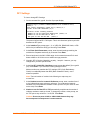
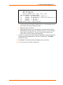
Multi-Master DF1 Protocol User Guide Part Number 900-282 Revision B August 2004 Copyright & Trademark © 2002, Lantronix. All rights reserved. No part of the contents of this book may be transmitted or reproduced in any form or by any means without the written permission of Lantronix. Printed in the United States of America. Ethernet is a trademark of XEROX Corporation. UNIX is a registered trademark of The Open Group. Windows 95, Windows 98, Windows 2000, and Windows NT are trademarks of Microsoft Corp. Netscape is a trademark of Netscape Communications Corporation. Contacts Lantronix Corporate Headquarters 15353 Barranca Parkway Irvine, CA 92618, USA Phone: 949-453-3990 Fax: 949-453-3995 Technical Support Phone: 800-422-7044 or 949-453-7198 Fax: 949-450-7226 Online: www.lantronix.com/support Sales Offices For a current list of our domestic and international sales offices, go to the Lantronix web site at http://www.lantronix.com/about/contact/index.html. Disclaimer & Revisions The information in this guide may change without notice. The manufacturer assumes no responsibility for any errors that may appear in this guide. Date Rev. Comments 9/6/02 A Initial Document 8/04 B Reformatted Multi-Master DF1 Protocol User Guide 2 Contents Figures 3 1: Overview 4 Multi-Master DF1 ____________________________________________________ 4 Summary of Features ________________________________________________ 4 2: Applications 5 RSLinx, HMI, or OPC ________________________________________________ 5 PLC to PLC Communication (MSG blocks) ________________________________ 5 3: Configuring Multi-Master DF1 7 Accessing the DF1 Setup Mode over Telnet _______________________________ 7 TCP/IP Network Settings______________________________________________ 8 DF1 Settings _______________________________________________________ 9 MSG Block Remote IP Routing Table ___________________________________ 10 Save, Quit, or Reset the Configuration __________________________________ 12 4: Q & A 13 5: Technical Support 15 Figures Figure 2-1. Computer to PLC .................................................................................................................5 Figure 2. - PLC to PLC ...........................................................................................................................5 Multi-Master DF1 Protocol User Guide 3 1: Overview Multi-Master DF1 A Lantronix IAP Device Server with Multi-Master DF1 firmware understands the DF1 protocol and therefore allows up to four remote masters to share a single DF1 FullDuplex device. In addition, the IAP Device Server with Multi-Master DF1 firmware allows the user to define a table to map the DF1 DST byte to one of many remote IPs. This feature allows you to set up a small peer-to-peer network. An IAP Device Server with Lantronix Standard Tunneling Firmware allows most DF1 serial slaves to be accessed remotely through Ethernet. However, the firmware is limited to one socket representing one master at a time. There is no way to have two masters access at once and share the serial port. Also, if the PLC uses MSG blocks to issue requests, the messages all must go to a single remote IP. For additional information about using Industrial Automation solutions, see http://www.lantronix.com/solutions/industrial/index.html. Summary of Features Multi-Master DF1 allows up to four remote sockets to connect to one serial DF1 fullduplex slave. These can be mixed as any combination of Com Port Redirector or raw sockets (for example, four of one and none of the other or two of each). Incoming redirector sockets are fixed at TCP port 14001. Users must set the Lantronix Com Port Redirector software on the Windows computer to port 3001. Full instructions are in the Tech Tips section of http://automation.lantronix.com. Users can set incoming raw DF1 sockets to any TCP port from 1024 to 65535 (except 14000 to 14009). All raw sockets share the same TCP port number. Outgoing DF1 requests – for example PLC MSG blocks - are “routed” to remote IPs based on the DST byte in the request. Since there is only a single active outgoing socket, you must issue MSG blocks one at a time to allow the sockets to be opened, an answer to be returned, and the to be socket closed. Multi-Master DF1 Protocol User Guide 4 2: Applications RSLinx, HMI, or OPC The most common use of the Multi-Master DF1 firmware is to allow two remote masters (for example, two HMI/OPC servers or one HMI and one RSLogix) to talk to the PLC at the same time. Figure 2-1. Computer to PLC The Multi-Master DF1 firmware understands the DF1 protocol enough to prevent conflict between the masters. For example, it prevents two remote copies of RSLogix from locking the PLC resources. The first will be granted the resource, and the second will be rejected as the resource is locked already. PLC to PLC Communication (MSG blocks) Another use is to allow the attached PLC to issue MSG blocks for peer-to-peer communications. While the picture at right just shows three PLCs, you could also have HMI masters and others attached to some or all of the PLCs. Figure 2. - PLC to PLC The Multi-Master DF1 firmware allows four incoming and one outgoing socket to be active at one time. This means in a simple example, that IAP Device Server-C with Multi-Master DF1 firmware can allow sockets from IAP Device Server-A, IAP Device Multi-Master DF1 Protocol User Guide 5 2: Applications Server-B, 2 x HMI, and still use its outgoing socket to query IAP Device Server-A and IAP Device Server-B. You only need the Multi-Master DF1 firmware on an IAP Device Server for which you want to support multiple sockets. For example, the three-node peer-to-peer would work fine if IAP Device Server-A and IAP Device Server-B are using Standard Tunneling firmware, and only IAP Device Server-C has Multi-Master DF1. If the MSG blocks are on the IAP Device Server-C, then it will open and move its outgoing socket between IAP Device Server-A and IAP Device Server-B. This design would literally allow IAP Device Server-C to poll hundreds of remote IAP Device Servers, one at a time. Likewise, if the MSG blocks are on IAP Device Server-A and IAP Device Server- B, then each can open and maintain a socket to IAP Device Server-C with Multi-Master DF1 firmware. In this design, you are limited to four, as the Multi-Master DF1 firmware only supports four active incoming sockets at one time. Note that the standard firmware in IAP Device Server-A and IAP Device Server-B should be set up as expected for a serial tunnel (see the Standard Tunneling Manual). Setting Flush Mode to 0x11 causes all stale DF1 data to be flushed from the buffers when a failed socket recovers (the PLC has no doubt forgotten about these messages anyway). Setting the Disconnect Time to a value like 30 seconds allows better multi-access to Standard Tunneling firmware on an IAP Device Server. Limitations: the outgoing socket must complete one full DF1 transaction before it can be moved to the next remote IP. This means that if IAP Device Server-C does want to use two MSG blocks to talk to IAP Device Server-A and IAP Device Server-B, the trigger logic must fire them sequentially one after the other – not at the same time. Multi-Master DF1 Protocol User Guide 6 3: Configuring Multi-Master DF1 As a member of Lantronix’s Industrial Automation Protocol (IAP) suite of products, the Multi-Master DF1 firmware can be loaded into any of the IAP family of products. DF1 is a serial communications protocol used by most Rockwell Automation’s (Allen Bradley) Programmable Controllers. Lantronix provides an intelligent Ethernet-enabling technology for the most commonly used Industrial Serial Protocols, including DF1. You must configure certain parameters before the IAP Device Server can be used on a network. Accessing the DF1 Setup Mode over Telnet You can use a Telnet connection to configure the unit over the network. 1. Access the Multi-Master DF1 Setup Mode screen via Telnet to port 9999 and the unit’s IP address. 2. Within 5 seconds, press Enter. The Setup Mode screen displays. Serial Number 6410064 MAC address 00:20:4A:64:27:50 Software version V01.0 (010321) Press Enter to go into Setup Mode Model: IAP Device Server Plus+! (Firmware Code:AD) Multi-Master DF1 1) TCP/IP Network Settings: Ethernet Autodetect IP addr 172.20.198.72, no gateway set, netmask 255.255.255.000 Telnet config password set 2) DF1 Settings: Protocol ................. DF1 Full-Duplex Serial Interface ......... RS232 19200,8,N,1 Check Sum ................ CRC (16-bit) Redirector Sockets ....... 2 (port:03001) Raw Tunneled Sockets ..... 2 (port:10001) 3) MSG Block Remote IP Routing Table: (* None Defined *) R)eset all to factory Defaults S)ave all to EEPROM and Quit Q)uit without saving Select Command or parameter set (1,2,R,S,Q) to change: Note: If you just reflashed the IAP Device Server with Multi-Master DF1 firmware, we recommend that you reset all of the parameters to the factory defaults. 3. To reset the parameters to the factory defaults, type R on the command line. The default parameters display. Multi-Master DF1 Protocol User Guide 7 3: Configuring Multi-Master DF1 4. Accept the defaults by pressing Enter at the prompts. In most cases, users choose to accept the defaults. TCP/IP Network Settings To view or change TCP/IP settings: 1. On the command line, type 1. A series of prompts display. IP Address : (192) .(168) .(000) .(249) Set gateway IP address (N) Y Gateway IP Address : (000) 192.(000) 168.(000) .(000) 1 Netmask: Number of Bits for Host Part (0=default) (00) Change telnet config password (N) N 2. The menu already displays the IP address. If you want to change it, at the IP Address prompt, type the new address, pressing Enter after each octet. The IP address must be set to a unique value in your network. To learn more about IP addressing, see the User Guide for your IAP Device Server. Note: The IAP Device Server will not connect to the network if the assigned IP address is already in use by another device. 3. At the Set Gateway IP Address prompt, accept the default or type the IP address of the default router connected to the same LAN segment as the IAP Device Server. The gateway address must be within the local network. Press Enter. The gateway address, or router, allows communication to other LAN segments. 4. At the Netmask prompt, accept the default or type the number of bits taken from the IP address that are assigned for the host section. Press Enter. Standard Class A: 24 bits; Standard Class B: 16 bits; Standard Class C: 8 bits. The IAP Device Server prompts for the number of host bits to be entered, then calculates the subnet mask. The subnet mask displays in standard decimal-dot notation (for example, 255.255.255.0) when the saved parameters display. 5. You can prevent unauthorized access to the setup menu via a Telnet connection to port 9999. At the Change Telnet configuration password prompt, type Y (Yes) and press Enter. Type a 4-character password and press Enter. Multi-Master DF1 Protocol User Guide 8 3: Configuring Multi-Master DF1 DF1 Settings To view or change DF1 Settings: 1. On the command line, type 2. A series of prompts display. Interface Type (1=RS232 2+RS422/RS485+4-wire 3=RS485+2-wire) (00001)? Enter serial parameters (19200,8,N,1) 9600,8,n,1 Use DF1 16-bit CRC CheckSum? (Y) Y You have 4 total incoming sockets: Number to use for Lantronix Redirector (00002) ?3 Number to use for Raw DF1 in TCP 1 TCP port to use for Raw DF1 (10001) ? The protocol is fixed at DF1 Full-Duplex. This is a bi-directional, point-to-point link between two DF1 peers. 2. At the Interface Type prompt, type 1, 2, or 3 (RS-232, RS422/485 4-wire, or RS485 2-wire) to indicate the wiring you are using. Press Enter. 3. At the Enter Serial Parameters prompt, enter the serial settings matching the serial device. Separate each entry by a comma. Press Enter. 4. Enter a baud rate in the 300-115200 range– but be aware that most PLCs work better at 9600 or 19.2K due to over-ambitious surge protection. 5. Normally, DF1 is fixed to 8 data bits, no parity, 1 stop bit – however, you may change this if you have special needs. 6. At the Use DF1 16-bit CRC CheckSum prompt, accept the default (Y) or type N (No). Press Enter. If you enter N, the setting changes to BCC. Make sure this entry matches the PLC settings. CRC (Cyclic Redundancy Check) is considerably better than BCC (Block Character Check)—use it whenever possible. Note: The total number of sockets in the following two steps may not exceed four. 7. At the Number to use for Lantronix Redirector prompt, enter a number from 0 to 4 to indicate how many sockets to redirect to. You must set the Lantronix Windows Com Port Redirector software to 3001 (but the TCP port 14001 is used on the wire). Press Enter. 8. Number to use for Raw DF1 in TCP automatically compliments the number of redirector sockets to make up 4 total. To change the number, at the prompt, set the TCP port to any value from 1 to 65,535. Press Enter. Caution: Do not use ports 0-1023 or 14001-14009 because they may have unexpected consequences in some networks. Multi-Master DF1 Protocol User Guide 9 3: Configuring Multi-Master DF1 MSG Block Remote IP Routing Table This is the mapping information that forwards or routes a DF1 message originated by the serial DF1 device. The DF1 firmware uses the DST (or destination) byte of the DF1 message to select (and possibly modify) the remote IP to access. You can define 5 entries – each with a range of DST addresses. But be aware that the DF1 firmware searches this table sequentially and will stop at the first match. 1. On the command line, type 3. A series of prompts display. MSG Block Remote IP Routing Table: 1) 000-000: --- not set --2) 000-000: --- not set --3) 000-000: --- not set --4) 000-000: --- not set --5) 000-000: --- not set --C)hange D)elete, E)xit – select function 2. Selecting Change or Delete will display the prompt: Which entry number DST from (000) DST to (000) 100 Slave IP address (192) .(168) .(000) .(000) 24 MSG Block Remote IP routing Table: 1) 000-100: 192.168.000.024 (* Fixed IP *) 2) 000-000: --- not set --3) 000-000: --- not set --4) 000-000: --- not set --5) 000-000: --- not set --C)hange D)elete, E)xit – select function Entering a fixed IP creates a fixed relationship of many DSTs to one remote IP. So in the example below, a DF1 message received for DST=7 would go to IP 192.168.0.24, as would messages for DST=55 or 73. Everything in that range goes to one IP. Entering a 4th octet as zero creates a dynamic entry where the DST becomes the 4th octet in the remote IP address. So in the example below, a DF1 message received for DST=110 would go to IP 192.168.0.110, and one for DST=205 would go to IP 192.168.0.205. For safer application, the DF1 firmware will not allow you to create an IP with the 4th octet of 000 or 255. Some networks treat an IP like 192.168.0.0 as shorthand for an entire subnet group, while most networks treat an IP like 192.168.0.255 as a broadcast. Multi-Master DF1 Protocol User Guide 10 3: Configuring Multi-Master DF1 Which entry number DST from (000) 101 DST to (000) 254 Slave IP address (192) .(168) .(000) .(000) MSG Block Remote IP routing Table: 1) 000-100: 192.168.000.024 (* Fixed IP *) 2) 101-254: 192.168.000.000 (* DST as low octet of IP *) 3) 000-000: --- not set --4) 000-000: --- not set --5) 000-000: --- not set --C)hange D)elete, E)xit – select function You have the option to change or delete an entry. You will be asked which of the five entries you want to change or delete. Deleting an entry just clears it. When changing an entry, you will be asked for the minimum and maximum DST address to include in the entry. These are inclusive—so in the example above, entry #1 includes DST = 0 to 100. You will also be asked for the remote IP to use for this range of DST addresses. 1. On lines 1-5, enter the fixed and/or dynamic IP addresses or address ranges that correspond to the message blocks in your PLC or serial device. Press Enter between each entry. 2. Press Enter. The window refreshes and displays all of your entries. Note: You must save your settings to apply them. Multi-Master DF1 Protocol User Guide 11 3: Configuring Multi-Master DF1 Save, Quit, or Reset the Configuration Multi-Master DF1 1) TCP/IP Network Settings: Ethernet Autodetect IP addr 192.168.0.249, gateway 192.168.000.001 2) DF1 Settings: Protocol ................. DF1 Full-Duplex Serial Interface ......... RS232 9600,8,N,1 Check Sum ................ CRC (16-bit) Redirector Sockets ....... 3 (port:03001) Raw Tunneled Sockets ..... 1 (port:10001) 3) MSG Block Remote IP Routing Table: 000-100: 192.168.000.024 (* Fixed IP *) 101-254: 192.168.000.000 (* DST as low octet of IP *) R)eset all to factory Defaults S)ave all to EEPROM and Quit Q)uit without saving Select Command or parameter set (1,2,R,S,Q) to change: 1. Review your entries. 2. You have the following options: To save the configuration and exit, type S on the command line. This saves the parameters to EEPROM. Caution: DO NOT POWER CYCLE the unit too fast after doing this. Allow the unit to reboot naturally one time first. To quit without saving, type Q on the command line. The unit reboots. To restore the default values, type R on the command line. Multi-Master DF1 Protocol User Guide 12 4: Q & A Can I use the Lantronix IAP Device Server with Multi-Master DF1 to link directly to the Ethernet port of a ControlLogix, PLC5/80E, or SLC5/05? No, the Multi-Master DF1 does not do protocol conversion. It only manages raw DF1 that has been encapsulated as is within TCP. The ControlLogix is talking CIP (Ethernet/IP) and the PLC5 and SLC5 are by default talking CSP (port 2222 or AB/Ethernet as it is sometimes called) or CIP if you enable “Multi-hop.” None of these PLCs can accept raw DF1 on a TCP socket. There are pros and cons of doing this either way. We have chosen the most generic, widely applicable way to support DF1 with TCP/IP. Does the IAP Device Server with Multi-Master DF1 autobaud? No, you must manually set the baud rate to match your PLC. When I use the Com Port Redirector, why doesn’t the baud rate I set for the virtual COM port seem to be accepted by the IAP Device Server? You must manually set the baud rate in your IAP Device Server to match your PLC. The baud rate and other information entered on the computer are not sent to the IAP Device Server. Can I multi-drop PLC with the IAP Device Server with Multi-Master DF1? No, this firmware only supports DF1 Full-Duplex (point-to-point) and not DF1 HalfDuplex (master-to-multiple-slaves). How do I select a cable for different Allen-Bradley PLCs? Micrologix Series Use the same cable as when using the Allen Bradley programming or communications software. SLC 500 Series If the PLC has an RS232 port, you can connect directly using a standard RS232 null modem cable. For the SLC-500 (SLC 5/03, 5/04, 5/05), you can use 1747-CP3 cable. The PLC port must be configured for DF1 communications, not DH-485 Master. PLC5 Series A direct connection can be made to the CH0 port of enhanced PLC5 processors using a standard RS232 null modem cable. The port must be configured for DF1 communications. Multi-Master DF1 Protocol User Guide 13 4: Q & A DH-485 Networks An Allen Bradley KF3 or compatible device is needed to connect to the DH-485 network. A standard null modem cable is used to connect the IAP Device Server to the KF3 device. DH+ Networks An Allen Bradley KF2 or compatible device is needed to connect to the DH+ network. A standard null modem cable is used to connect the IAP Device Server to the KF2 device. Multi-Master DF1 Protocol User Guide 14 5: Technical Support 5: Technical Support If you are experiencing an error that is not described in this user guide, or if you are unable to fix the error, you may: Check our online knowledge base at http://www.lantronix.com/support. Contact Technical Support in the US: Phone: 800-422-7044 (US only) or 949-453-7198 Fax: 949-450-7226 Our phone lines are open from 6:00AM - 5:30 PM Pacific Time Monday through Friday, excluding holidays. Contact Technical Support in Europe, Middle East, and Africa: Phone: +49 (0) 89 31787 817 Email: [email protected] Firmware downloads, FAQs, and the most up-to-date documentation are available at: http://www.lantronix.com/support When you report a problem, please provide the following information: Your name, and your company name, address, and phone number Lantronix model number Lantronix serial number Software version (on the first screen shown when you Telnet to port 9999) Description of the problem Debug report (stack dump), if applicable Status of the unit when the problem occurred (please try to include information on user and network activity at the time of the problem) Multi-Master DF1 Protocol User Guide 15