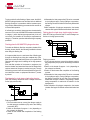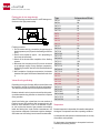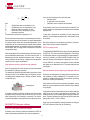
1
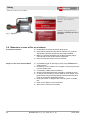
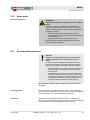
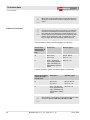
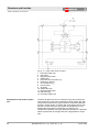
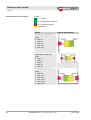
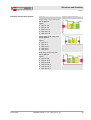
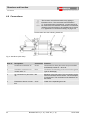
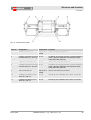
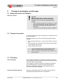
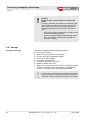
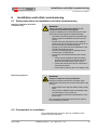
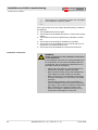
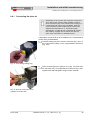
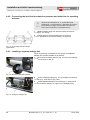
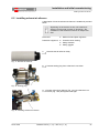
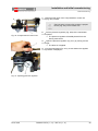
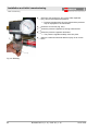
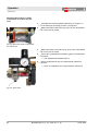
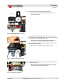
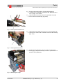
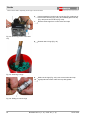
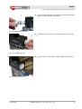
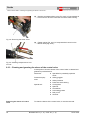
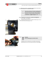
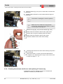
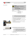
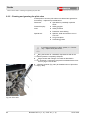
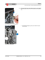
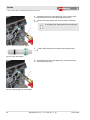
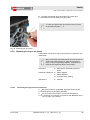
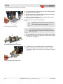
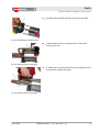
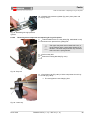
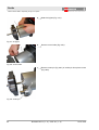
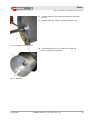
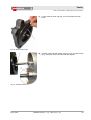
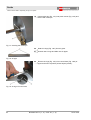
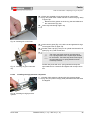
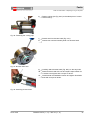
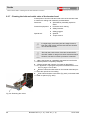
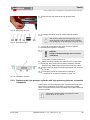
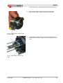
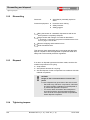
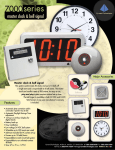
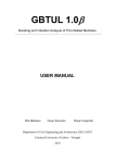
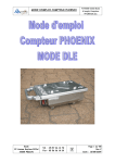
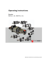
Faults
Fault correction tasks > Replacing O-ring on air piston
3.
Unscrew inlet and outlet line (Fig. 55/1) from inlet and outlet
connection of booster head.
4.
Close openings of removed inlet and outlet line with sealing
plug to protect these against soiling.
5.
Undo fixing bolts of booster from foundation and secure to
prevent them from getting lost.
6.
Remove line from drive air connection.
Depending on the version, drive air connection
PL is connected to the compressed air control
unit or to the control valve housing.
Fig. 55: Inlet and outlet line
In a dual-acting booster, the cooling pipe must be
removed from the high pressure components and the
inlet connections.
7.
Undo threaded union of cooling pipe from both high pressure
components (Fig. 56/2) and from inlet connections (Fig. 56/1)
and remove cooling pipe.
8.
Undo the four nuts of the stay bolts on the booster head
(Fig. 57/marked in red) with a spanner. Secure nuts and
square taper washer for U-sections to prevent them from getting lost.
Fig. 56: Removing the cooling pipe
Fig. 57: Undoing the booster head
86
Boosters DLE 2 (-1, -2) – DLE 75 (-1, -2)
26.01.2012