1
LPX-600
User’s Manual
Thank you very much for purchasing this product.
➢ To ensure correct and safe usage with a full understanding of this product's performance, please be
sure to read through this manual completely and store it in a safe location.
➢ Unauthorized copying or transferral, in whole or in part, of this manual is prohibited.
➢ The contents of this operation manual and the specifications of this product are subject to change
without notice.
➢ The operation manual and the product have been prepared and tested as much as possible. If you
find any misprint or error, please inform us.
➢ Roland DG Corp. assumes no responsibility for any direct or indirect loss or damage which may
occur through use of this product, regardless of any failure to perform on the part of this product.
➢ Roland DG Corp. assumes no responsibility for any direct or indirect loss or damage which may
occur with respect to any article made using this product.
For the USA
FEDERAL COMMUNICATIONS COMMISSION
RADIO FREQUENCY INTERFERENCE
STATEMENT
This equipment has been tested and found to comply with the
limits for a Class A digital device, pursuant to Part 15 of the
FCC Rules.
These limits are designed to provide reasonable protection
against harmful interference when the equipment is operated
in a commercial environment.
This equipment generates, uses, and can radiate radio
frequency energy and, if not installed and used in accordance
with the instruction manual, may cause harmful interference
to radio communications.
Operation of this equipment in a residential area is likely to
cause harmful interference in which case the user will be
required to correct the interference at his own expense.
Unauthorized changes or modification to this system can void
the users authority to operate this equipment.
The I/O cables between this equipment and the computing
device must be shielded.
For Canada
CLASS A
NOTICE
This Class A digital apparatus meets all requirements of the
Canadian Interference-Causing Equipment Regulations.
CLASSE A
AVIS
Cet appareil numérique de la classe A respecte toutes les
exigences du Règlement sur le matériel brouilleur du
Canada.
ROLAND DG CORPORATION
1-6-4 Shinmiyakoda, Hamamatsu-shi, Shizuoka-ken, JAPAN 431-2103
MODEL NAME
: See the MODEL given on the rating plate.
RELEVANT DIRECTIVE : EC LOW VOLTAGE DIRECTIVE (73/23/EEC)
EC ELECTROMAGNETIC COMPATIBILITY DIRECTIVE (89/336/EEC)
This system (including the housing and safety device) is a Class 1 laser product.
Laser specifications of this system (including the housing)
Wavelength: 645 to 660 nm, maximum output: less than 0.39 µW
Complied with IEC/EN Publication 60825-1, Amendment 2, 2001.
Complies with 21 CFR 1040.10 and 1040.11 except for deviations pursuant to Laser Notice No.50, dated July 26, 2001.
CAUTION
Use of controls or adjustments or performance of procedures other than those specified herein may result in radiation exposure.
Table of Contents
To Ensure Safe Use ....................................................................................................................... 3
Important Notes on Handling and Use ............................................................................................. 7
About the Documentation .................................................................................................................. 8
1. Getting Started ................................................................................................................................. 9
1-1 What Is the LPX-600? ......................................................................................................................................... 10
Features ......................................................................................................................................... 10
Scanning System ............................................................................................................................ 10
1-2 Names and Functions ......................................................................................................................................... 11
About the Indicator Lights ............................................................................................................. 12
2. Preparing the Machine ................................................................................................................... 13
2-1 Checking Accessaries .......................................................................................................................................... 14
2-2 Installing .................................................................................................................................................................. 16
Deciding On an Installation Site ................................................................................................... 16
Removing the Protective Material .................................................................................................. 17
2-3 Connecting the Cables ....................................................................................................................................... 18
Attaching the Cable Clamps and the AC Adapter Holder .............................................................. 18
Connecting the Cables .................................................................................................................. 18
2-4 Installing and Setting Up the Software ............................................................................................................ 20
Installing the Driver ....................................................................................................................... 20
Installing the Programs .................................................................................................................. 26
Making the Settings for Using Dr.PICZA3 ...................................................................................... 27
3. Creating 3D Data ............................................................................................................................ 29
3-1 Task Flow ................................................................................................................................................................ 30
3-2 Mounting the Scan Object ................................................................................................................................. 31
Preparing the Scan Object ............................................................................................................. 31
Mounting the Scan Object ............................................................................................................ 33
3-3 Performing Scanning ............................................................................................................................................ 34
Basic Scanning .............................................................................................................................. 34
Checking the Scanning Results ...................................................................................................... 37
3-4 Finishing the Data ................................................................................................................................................ 38
Selecting and Scanning a Specific Area ......................................................................................... 38
Creating New Polygons ................................................................................................................. 42
3-5 Saving and Exporting Data ................................................................................................................................. 43
Saving Data ................................................................................................................................... 43
Exporting Data ............................................................................................................................... 43
1
Contents
4. Editing Scanning Results - Using 3D Editor ................................................................................. 45
4-1 What You Can Do Using 3D Editor ................................................................................................................ 46
4-2 Importing and Exporting Data .......................................................................................................................... 47
Importing Scanning Results Immediately ....................................................................................... 47
Importing and Exporting ................................................................................................................ 47
Importing More Than One Set of Data ........................................................................................... 47
4-3 Basic Operations for Objects ........................................................................................................................... 48
How to View the 3D Editor Window ............................................................................................. 48
Let's Try Editing Data with 3D Editor ............................................................................................. 49
5. What to Do If... ................................................................................................................................ 53
5-1 What to Do If... .................................................................................................................................................... 54
5-2 When Moving the Machine ................................................................................................................................ 56
6. Appendix .......................................................................................................................................... 57
6-1 Table Dimensional Drawing ............................................................................................................................... 58
6-2 Locations of the Power Rating and Serial Number Labels ........................................................................ 59
6-3 Specifications ......................................................................................................................................................... 60
Machine Specifications ................................................................................................................. 60
System Requirements for the Software ........................................................................................... 60
System Requirements for USB Connection .................................................................................... 60
Windows® is registered trademark or trademark of Microsoft® Corporation in the United States and/or other countries.
Pentium is registered trademark of Intel Corporation in the United States.
Other company names and product names are trademarks or registered trademarks of their respective holders.
Copyright© 2005 Roland DG Corporation
2
http://www.rolanddg.com/
To Ensure Safe Use
Improper handling or operation of this machine may result in injury or damage to property.
Points which must be observed to prevent such injury or damage are described as follows.
About
WARNING and
WARNING
CAUTION Notices
Used for instructions intended to alert the user to the risk of death or severe
injury should the unit be used improperly.
Used for instructions intended to alert the user to the risk of injury or material
damage should the unit be used improperly.
CAUTION
* Material damage refers to damage or other adverse effects caused with respect to the home and all its furnishings, as well to domestic animals or pets.
About the Symbols
The
symbol alerts the user to important instructions or warnings. The specific meaning of
the symbol is determined by the design contained within the triangle. The symbol at left means
"danger of electrocution."
The
symbol alerts the user to items that must never be carried out (are forbidden). The
specific thing that must not be done is indicated by the design contained within the circle. The
symbol at left means the unit must never be disassembled.
The symbol alerts the user to things that must be carried out. The specific thing that must be
done is indicated by the design contained within the circle. The symbol at left means the powercord plug must be unplugged from the outlet.
Incorrect operation may cause injury
WARNING
Do not disassemble, repair, or modify.
Doing so may lead to fire or abnormal operation resulting in injury.
Never allow children near the machine.
The machine includes locations and components
that pose a danger to children, and accidental
injury may occur.
3
To Ensure Safe Use
Incorrect operation may damage the scan object
WARNING
Securely fasten the object to be scanned
to the table so that it does not slip or
topple over.
The table rotates during scanning. Tipover or
contact by the scan object may cause damage.
Scan-object damage is not covered by warranty.
Never try to scan an object whose height
is 406.4 mm or more, or that protrudes
beyond the table.
The object may strike the interior of the machine, causing breakdown or damage. The scan
object may also be damaged. Scan-object damage is not covered by warranty.
This machine weighs approximately 60 kg (135 lb.).
WARNING
Lifting and carrying are operations that
must be carried out by four or more persons, by grasping the bottom of the machine.
Failure to do so may result in falling of the unit,
leading to injury.
Install on a stable surface.
Failure to do so may result in the unit tipping
over, leading to injury.
External emission of laser light may occur
WARNING
Do not use if the housing or window area
is cracked or deformed.
In such cases, there is danger of external emission of Class 3R laser light. Staring at externally
emitted laser light may cause eye injury.
Important Cautions Regarding Laser Light
This machine uses a laser beam to scan objects, but dangerous laser radiation is not emitted outside the machine. It is safe
to view the laser light through the window.
However, this may not be the case if the machine is disassembled or if its cover or safety devices are broken or disabled.
Please observe the cautionary notes in this documentation and never attempt to use this machine if the machine is in an
abnormal state.
Direct contact with the laser beam will not cause burns or fire due to incorrect use or the like. The natural blink reflex
protects the eye in the event that laser light from the machine directly enters the eye, but staring directly into the laser beam
may result in eye injury.
4
To Ensure Safe Use
Danger of electrical short, shock, electrocution, or fire
WARNING
Do not use with any electrical power supply that does not meet the ratings displayed on the AC adapter.
Use with any other power supply may lead to
fire or electrocution.
When unplugging the electrical power
cord from the power outlet, grasp the plug,
not the cord.
Unplugging by pulling the cord may damage it,
leading to fire, electrical shock, or electrocution.
Do not use with any power supply other
than the dedicated AC adapter.
Use with any other power supply may lead to
fire or electrocution.
When not in use for several hours, unplug
the power-cord plug from the electrical
outlet.
Failure to do so may result in danger of electrical shock, electrocution or fire due to deterioration of electrical insulation.
Never use any power cord other than the
power cord included with the machine.
Doing so may cause fire.
Do not use with a damaged AC adapter,
power cord or plug, or with a loose electrical outlet.
Doing so may lead to fire, electrical shock, or
electrocution.
Never damage the power cord or pull it
with force.
Doing so may tear the cord's insulation, causing
an electrical short and resulting in electrical
shock, electrocution, or fire.
Never place any object on the power cord,
bend the power cord using excessive force,
or allow the power cord to become deformed.
If it becomes deformed, the deformed location
may grow hot and cause fire.
Never operate the machine or insert or
remove its power plug with wet hands.
Doing so may result in electrical shock or electrocution.
In the event of an abnormal state (such as
smoke or sparks, odor or burning or unusual noise), immediately unplug the
power cord.
Failure to do so may result in fire, electrical
shock, or electrocution. Immediately disconnect
the power cord and contact your Roland DG
Corp. service center.
Never insert metal objects, flammable
objects, or any other foreign object into
interior areas other than the top of the
table. Also, do not place water or other
liquids on any area, including the table.
Doing so may cause an electrical short, resulting in shock or electrocution, or the inserted
object may catch fire.
5
To Ensure Safe Use
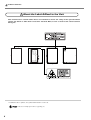
About the Labels Affixed to the Unit
This machine bears caution labels. These are intended to ensure the safety of the operator. Never
remove the labels or allow them to become obscured. Also, be sure to observe the stated cautions
during use.
Left
Front
In addition to these symbols, the symbol shown below is also used.
: Indicates a handy tip or advice regarding use.
6
Right
Rear
Important Notes on Handling and Use
This machine is a precision device. To ensure the full performance of this machine, be sure to
observe the following important points. Failure to observe these may not only result in loss of
performance, but may also cause malfunction or breakdown.
Main Unit
This Machine Is a Precision Device
➢Handle carefully, and never subject the machine to impact or excessive force.
➢Never touch any internal component except the table. Doing so may make scanning impossible.
Install in a Suitable Location
➢Install in a location having the specified temperature and relative humidity.
➢Install in a stable location offering good operating conditions.
Never Touch the Machine During Scanning
➢Never subject the machine to impact during a scanning operation. Doing so may cause scanning noise.
➢Except in an emergency, never open the machine's door during a scanning operation. Doing so switches off the
power, and scanning operation cannot be resumed.
Important Notes on Connecting the Cables
➢Connect the AC adapter, power cord, and USB cable securely so that they do not come loose or experience
faulty connection during use.
➢Be sure to use the included USB cable.
➢Never use a USB hub or the like.
7
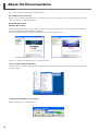
About the Documentation
This machine comes with the following documentation.
User's Manual (this document)
Read this first. It contains important notes and cautions on usage, as well describing scanning methods, what to do in the
event of a problem, and other information.
Dr.PICZA3 Online Help
3D Editor Online Help
You view this documentation on your computer screen. Installing the program enables you to view the documentation.
☞ See "2-4 Installing and Setting Up the Software."
It provides detailed descriptions of the commands you use for each of the programs.
You can use either of two methods to view the documentation.
• From the [Start] Menu in Windows
From the [Start] menu, choose [All programs (or Programs)], then [Roland Dr.PICZA3 (Roland 3D Editor)], then [Dr.PICZA3
(3D Editor) Help].
• Clicking the Help Menu in the Program
From the [Help] menu, click [Contents].
8
1. Getting Started
9
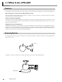
1-1 What Is the LPX-600?
Features
The LPX-600 is a three-dimensional (3D) scanner that uses a noncontacting laser method to scan the shape of solid objects.
Noncontacting Laser System for Fast, Dependable Scanning
You can perform scanning without contact with the scan object, using a laser beam. This enables high-speed scanning
without the worry of damage to the object.
Support for Two Scanning Modes
Using the included Dr. PICZA3 program lets you perform scanning in either of two modes: plane scan or rotary scan. You
can choose the scanning mode that matches the shape of the scan object. By combining the two modes, you can even scan
objects with complex shapes.
A Wide Array of Scanning Functions
In addition to the two basic scanning modes, line-segment and point scanning functions are also supported. By using Dr.
PICZA3, you can extract the data for just the characteristic line segments (such as contour lines) and points of an object.
Using this as auxiliary data for three-dimensional modeling operations using CAD or computer-graphics programs makes it
possible to reduce the time and effort of modeling operations.
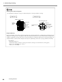
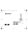
Scanning System
The LPX-600 scans objects using laser light. It emits a spot beam onto the scan object and detects reflected light from the
object with sensors.
Laser emitter
Sensor
It performs scanning as it rotates the scan object and moves the laser beam from bottom to top.
Rotating table
10
1. Getting Started
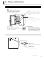
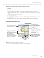
1-2 Names and Functions
Front
Door
When performing scanning, be sure to close
this. The power cannot be switched on while
the door is open. Opening the door while the
power is on switches off the machine.
Table
This is the base where you place objects to
be scanned. It rotates during scanning.
Never touch any internal area other than
the table.
Interlock switch
This is one of the safety devices. Never insert any objects here. Doing so may keep
the door open and prevent the safety devices from working properly.
Power button
Movement lights
These are arranged in a ring around the
power button. They flash when the machine
is performing some operation.
This switches the power on and off. To
switch on the power, you press this button.
To switch off the power, you hold it down
for one second or longer. The color of the
light indicates the status of the machine.
Rear
USB connector
This connects the included USB cable.
AC adapter jack
This connects the AC adapter.
1. Getting Started
11
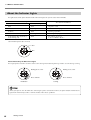
1-2 Names and Functions
About the Indicator Lights
The lighted state of the power button and the movement lights tells you the status of the LPX-600.
Indicator lights
Power button
The status of the LPX-600
Movement lights
Dark
Dark
The power is off.
Lit (blue)
Flashing two at a time
Initialization is in progress.
Lit (blue)
Dark
Scanning is possible.
Lit (blue)
Flashing one at a time
Scanning is in progress.
Lit or flashing (blue and red) (*)
Lit or flashing (red)
Dark
An error has occurred.
☞ See "5-1 What to Do If..."
(*)Illumination pattern (blue and red)
Red
Blue
Status Indicated by the Movement Lights
These light up blue and move clockwise two at a time during initialization at powerup, and one at a time during scanning.
Initialization
Flashing two at a time
Flashing one at a time
Move clockwise
Move clockwise
Scanning
When you open or close the door after connecting the power cord to the machine, the power button and movement
lights flash momentarily, but this is normal and does not indicate a problem.
12
1. Getting Started
2. Preparing the Machine
This section describes what to do when you first open the packing, including
how to connect the machine to a computer and install the programs and the
like.
13
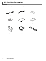
2-1 Checking Accessaries
The following items are packed with the machine. Make sure they are all present and accounted for.
14
AC adaptor: 1
Power cord: 1
Clay: 1
CD-ROM: 1
User's manual: 1
Scanning software: 1
AC adaptor holder: 1
USB cable: 1
Cable clamp: 3
2. Preparing the Machine
2-1 Checking Accessaries
2. Preparing the Machine
15
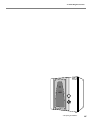
2-2 Installing
Deciding On an Installation Site
Install in a stable location offering good operating conditions. An unsuitable location can cause accident, faulty operation,
or breakdown.
CAUTION
Install on a stable surface.
Failure to do so may result in the unit tipping over, leading to injury.
CAUTION
Lifting and carrying are operations that must be carried out by four or more persons.
Failure to do so may result in falling of the unit, leading to injury.
Unsuitable Installation Sites
➢Locations with excessive humidity or dust
➢Locations subject to high temperature
➢Locations subject to shaking or vibration
➢Locations exposed to considerable electrical or magnetic noise, or other forms of electromagnetic energy
➢Locations with poor heat radiation
Power cord
506 mm
Height 761 mm
Leave enough space to the right side
and the rear of the machine to allow
the power cord to be reached by
hand at all times.
630 mm
Top view
16
2. Preparing the Machine
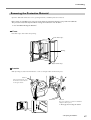
2-2 Installing
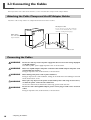
Removing the Protective Material
Open the door and remove the screws, packing materials, and other protective material.
Never touch or manually try to move any of the internal components. Doing so may result in breakdown.
The protective material is required when moving the machine. Do not discard it.
☞ See "5-2 When Moving the Machine."
Front
Peel off the tape and remove the packing.
Peel off the tape.
Packing
Peel off the tape.
Interior
With your fingers, loosen and remove the screws securing the table and head in place.
Screw 1
After removing them, store
them in the location shown
in the figure below.
Screw 2
These are needed to secure the included AC
adapter holder in place.
☞ Next page "Connecting the Cables"
2. Preparing the Machine
17
2-3 Connecting the Cables
When you connect the cables to the machine, use the included cable clamps and AC adapter holder.
Attaching the Cable Clamps and the AC Adapter Holder
Attach the cable clamps and the AC adapter holder to the back of the machine.
AC adaptor holder
Secure in place using the retaining
screws for the head (the two screws
"Screw 2" on the previous page).
Cable clamps
Peel off the double-sided
tape and attach.
Screw 2
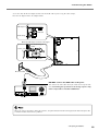
Connecting the Cables
WARNING
Do not use with any electrical power supply that does not meet the ratings displayed
on the AC adapter.
Use with any other power supply may lead to fire or electrocution.
WARNING
Never use any AC adapter and power cord other than the AC adapter and power cord
included with the machine.
Doing so may lead to fire, electrical shock, or electrocution.
WARNING
Never damage the power cord or pull it with force.
Doing so may tear the cord's insulation, causing an electrical short and resulting in electrical
shock, electrocution, or fire.
WARNING
Never place any object on the power cord, bend the power cord using excessive force,
or allow the power cord to become deformed.
If it becomes deformed, the deformed location may grow hot and cause fire.
WARNING
Do not use with a damaged AC adapter, power cord or plug, or with a loose electrical
outlet.
Doing so may lead to fire, electrical shock, or electrocution.
18
2. Preparing the Machine
2-3 Connecting the Cables
Secure the cable for the AC adapter and the incleded USB cable in place using the cable clamps.
Place the AC adapter on the AC adapter holder.
AC adaptor
USB cable
Cable clamp
Orient the AC adapter as shown in the figure.
The "Roland" logo is
visible.
Power cord
AC adaptor holder
Electrical outlet
DO NOT connect the USB cable at this point.
You connect the USB cable when you install and set up the software. Performing this operation in the wrong sequence may
make it impossible to install the USB driver.
Computer
USB port
When you connect the power cord to the machine, the power button and movement lights flash momentarily, but this
is normal and does not indicate a problem.
2. Preparing the Machine
19
2-4 Installing and Setting Up the Software
Here you connect the machine to your computer and install and set up the included software on the computer, enabling
you to perform scanning with the machine.
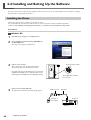
Installing the Driver
Connect the machine to the computer and install the driver.
Be sure to follow this procedure to install the driver. Failure to do so may make installation impossible.
☞ Go to "2-4 Installing and Setting Up the Software," see "What to Do If Installation Is Impossible."
Procedure
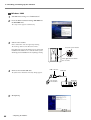
Windows XP
1
Start Windows and log on as "Administrator."
2
Insert the Roland Software Package CD-ROM into
the CD-ROM drive.
The setup menu appears automatically.
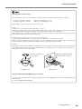
3
Press the power button.
Switch on the machine.
Wait a short while until the light stops flashing.
The flashing continues for about one minute.
From this point on, keep the machine's door closed until
installation ends. Failure to do so switches off the power,
which may prevent installation from completing correctly.
These lights flash clockwise
two at a time.
4
Connect the included USB cable.
USB connector
USB cable
The [Found New Hardware Wizard] dialog appears.
Computer
The back of
the machine
USB port
20
2. Preparing the Machine
2-4 Installing and Setting Up the Software
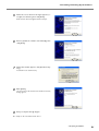
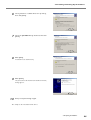
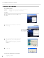
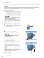
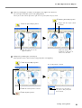
5
When the screen shown in the figure appears, select [No, not this time], then click [Next].
If the screen does not appear, refer to step 6.
6
Choose [Install the software automatically], then
click [Next].
7
When this window appears, click [Continue Anyway].
Installation starts automatically.
8
Click [Finish].
9
Carry out steps 5 through 8 again.
The [Welcome to the Found New Hardware Wizard]
dialog appears.
This completes the installation of the driver.
2. Preparing the Machine
21
2-4 Installing and Setting Up the Software
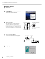
Windows 2000
1
Start Windows and log on as "Administrator."
2
Insert the Roland Software Package CD-ROM into
the CD-ROM drive.
The setup menu appears automatically.
3
Switch on the machine.
Wait a short while until the light stops flashing.
The flashing continues for about one minute.
Press the power button.
From this point on, keep the machine's door closed until
installation ends. Failure to do so switches off the power,
which may prevent installation from completing correctly.
These lights flash clockwise
two at a time.
4
Connect the included USB cable.
USB connector
USB cable
The [Found New Hardware Wizard] dialog appears.
The back of
the machine
Computer
USB port
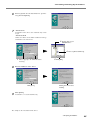
5
22
Click [Next].
2. Preparing the Machine
2-4 Installing and Setting Up the Software
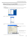
6
Select [Search for a suitable driver for my device],
then click [Next].
7
Select the [CD-ROM drives] check box, then click
[Next].
8
Click [Next].
9
Click [Finish].
10
Installation starts automatically.
The [Welcome to the Found New Hardware Wizard]
dialog appears.
Carry out steps 5 through 9 again.
This completes the installation of the driver.
2. Preparing the Machine
23
2-4 Installing and Setting Up the Software
Windows Me/98 SE
1
Start Windows.
2
Insert the Roland Software Package CD-ROM into
the CD-ROM drive.
The setup menu appears automatically.
3
Switch on the machine.
Press the power button.
Wait a short while until the light stops flashing.
The flashing continues for about one minute.
From this point on, keep the machine's door closed until
installation ends. Failure to do so switches off the power,
which may prevent installation from completing correctly.
4
Connect the included USB cable.
The [Add New Hardware Wizard] dialog appears.
These lights flash clockwise
two at a time.
USB connector
USB cable
The back of
the machine
Computer
USB port
5
24
Click [Next].
2. Preparing the Machine
2-4 Installing and Setting Up the Software
6
Choose [Search for the best driver for your device], then click [Next].
7
• Windows Me
Installation of the driver starts automatically. Go to
step 9.
• Windows 98 SE
Choose the folder on the Roland Software Package
CD-ROM to search the driver.
3
Double-click on your
CD-ROM drive.
4
1
8
Choose [Specify a
location].
2
Click the button.
Click [OK].
Execute installation of the driver.
Click [Next].
9
5
Choose [\Drivers\LPX-600].
Clicking this button starts
installing.
Click [Finish].
Installation is executed automatically.
This completes the installation of the driver.
2. Preparing the Machine
25
2-4 Installing and Setting Up the Software
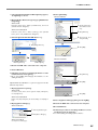
Installing the Programs
Install the following programs.
Dr.PICZA3
3D Editor
This program enables you to perform scanning using the machine.
This program enables you to edit scanned 3D data.
Procedure
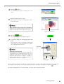
1
Make sure the screen shown in the figure is displayed.
2
Follow the on-screen instructions to start installation and setup.
Clicking the button
starts installing.
Select [LPX-600].
Make sure that all the
boxes be checked.
3
When the screen shown in the figure appears, click
"Next." Thereafter, follow the on-screen instructions.
When all installation and setup finishes, the final window appears.
4
Click [Close].
This completes the installation of the included software.
26
2. Preparing the Machine
2-4 Installing and Setting Up the Software
Making the Settings for Using Dr.PICZA3
You use the included Dr. PICZA3 program to make the settings that let you perform scanning with the machine.
Procedure
1
Start Dr.PICZA3.
2
Go to the [File] menu and click [Preferences].
3
Make the setting for the communication port and the unit of measurement to use with Dr. PICZA3.
From the [Start] menu, choose [All programs (or Programs)], then [Roland Dr.PICZA3], then [Dr.PICZA3].
Click this after you complete making
the setting.
Choose the number of the port labeled
"(Roland LPX-600 USB Port)."
Set [Units] to either [mm] or [inch].
This completes all the preparations you need to make to perform scanning using the machine.
2. Preparing the Machine
27
28
3. Creating 3D Data
This chapter describes how to create 3D data using the machine and the
included Dr. PICZA3 program.
29
3-1 Task Flow
This machine can scan three-dimensional shapes using the included Dr. PICZA3 program. To make 3D data obtained by
scanning available for use by other programs, you need to convert and save the data using Dr. PICZA3.
This section describes the sequence of operations from getting ready to scan through to saving the 3D data.
1
Prepare the object to be scanned and mount it on the machine.
Check whether the object you want to scan (we'll call this the "scan object") is suitable for scanning, and if so,
mount it on the machine.
☞ See "3-2 Mounting the Scan Object."
2
Perform scanning.
Use Dr. PICZA3 to carry out scanning (basic scanning).
☞ See "3-3 Performing Scanning."
3
Finish the data.
After the basic scanning, you finish the data to the appropriate degree by performing additional scanning and
creating polygon meshes as required.
☞ See "3-4 Finishing the Data."
4
Save the data.
Save the finished data in a file format compatible with the program you're using.
☞ See "3-5 Saving and Exporting Data."
Using the included 3D Editor program lets you import directly and edit data scanned with Dr. PICZA3.
☞ See "4. Editing Scanning Results -- Using 3D Editor."
30
3. Creating 3D Data
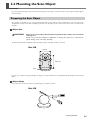
3-2 Mounting the Scan Object
First, you prepare the object to be scanned. After making sure the object is one that can be scanned, you mount the object
on the machine.
Preparing the Scan Object
This machine is not able to scan every possible kind of object. Some objects may be impossible to scan because of their
composition or shape. Refer to the following and make sure the object to be scanned is one that can be scanned on this
machine.
Object Size
CAUTION
Never try to scan an object that protrudes beyond the table or whose size exceeds the
scanning area.
Doing so may cause the machine to malfunction or damage the object to be scanned. Scanobject damage is not covered by warranty.
An object that protrudes beyond the table or whose height is too high cannot be scanned.
Not OK
254 mm
406.4 mm
Table
In such cases, consider separating the object into pieces whose individual sizes do not protrude beyond the area described
above.
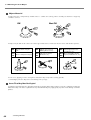
Object Shape
Areas where the laser beam strikes at a shallow angle cannot be scanned.
Not OK
20 degrees
or less
3. Creating 3D Data
31
3-2 Mounting the Scan Object
Object Material
An object that has a comparatively smooth surface is suitable for scanning. Fabrics and objects that have a rough nap
cannot be scanned.
OK
Not OK
An object may be difficult to scan because of the type of material it is made of, or because of its color or other qualities.
OK
Objects that do not pass
light
Not
Clear or transparent objects
OK
OK
Brightly colored objects
(White, yellow, red, etc.)
Not Dark-colored objects
OK (black, blue, etc.)
Objects of a nonglossy
OK material (plaster, wood, or
modeling clay etc.)
Not Glossy and highly reflective
OK objects (metals, mirrors, etc.)
In such cases, applying a surface coat (primer coat) to the object may make scanning possible.
(*) Avoid highly reflective objects because of danger of eye injury.
Items That May Not Be Copied
Unauthorized reproduction of a copyrighted item for any purpose other than personal use may be a violation of copyright.
Roland DG Corp. will not be responsible for any violation of third-party copyright by any article made through use of this
product.
32
3. Creating 3D Data
3-2 Mounting the Scan Object
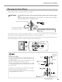
Mounting the Scan Object
Choose the object to be scanned, then mount the scan object.
CAUTION
Securely fasten the object to be scanned to the table so that it does not slip or topple
over.
The table rotates during scanning. Tipover or contact by the scan object may cause damage.
Scan-object damage is not covered by warranty.
Mount in the center of the table.
Table
Secure the bottom surface in
place with clay or the like.
Never damage or block the notch on
the table. Doing so may make scanning
impossible.
Table centerline
The table rotates during scanning. Using double-sided tape, clay, or the like, fasten the object in place securely so that it
will not fall over or slip. Any slipping of the object makes correct scanning impossible.
When the object to be scanned has areas with cavities or voids, mounting the object at an orientation that allows the laser
beam to pass through the cavities, as shown in the figure, makes scanning easier.
Scan object
Orientation of
the laser beam
Cavity
Table
Orientation
of the laser
beam
Effective Sensor Area
The figure at right shows the area in which the machine's sensors detect the reflection of the laser beam, allowing the object to be scanned.
The surfaces that reflect laser light as the table rotates and the
object passes through this area can be scanned.
When scanning an object that is considerably uneven, or that
is crank-shaped, you may need to take this effective sensor
area into account.
If the object is mounted at the edge of the table, it may not be
possible to scan the entire object correctly.
In the case of the apple shown at right, the area enclosed by
the shaded portion is not scanned.
254 mm
406.4 mm
Effective Sensor
Area
3 mm
Table
10 mm
Not OK
Outside the effective
sensor area
Not reached by the
laser beam
3. Creating 3D Data
33
3-3 Performing Scanning
Once you have mounted the object of the machine, you can now perform scanning.
Before you start scanning, make sure the door is closed and turn on the machine.
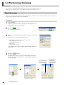
Basic Scanning
This is the scanning that you perform first after mounting the scan object. The scanning data obtained by executing basic
scanning makes possible a wide variety of operations.
Procedure
1
Start Dr.PICZA3.
2
Click the [
3
Choose the scanning mode that matches the shape of the scan
object.
From the [Start] menu, choose [All programs (or Programs)], then
[Roland Dr.PICZA3], then [Dr.PICZA3].
] button.
The [Scan] dialog box appears.
Click one of these buttons.
The [Settings for Scanning] dialog box appears.
• Object whose shape is close to a sphere or cylinder
• Object with little unevenness
Choose rotary scanning.
• Other object
Choose plane scanning.
You normally choose plane scanning, which has little restrictions
as to shape.
4
Click the [
] button.
The preview starts.
From this point on, never open the door until scanning ends. Doing so
switches off the power. Scanning cannot be resumed when you then switch
on the power again.
The general shape of
the object to be
scanned is displayed.
The height of the
scanning area is
setting automatically at this time.
Click
Preview in progress
34
3. Creating 3D Data
After preview has finished
3-3 Performing Scanning
5
While viewing the preview, make the following settings, then start scanning.
Scanning pitch
Using a fine setting can reproduce details more accurately, but the amount of memory required increases, and
scanning takes longer time.
Scanning area
Specify the minimum area that allows the entire object to be scanned, thereby speeding up scanning time.
* When [Set for Each Surface] is selected, you can set the scanning area and scanning pitch individually for each
surface.
(The following settings are only for plane scanning.)
The number of scanning surfaces
You can specify from one to as many as six surfaces. It's a good idea to decide on the number of surfaces to match
the shape of the object.
Scanning angle
Specify the incident angle of the laser for each surface. It may be a good idea to set the preview to Top View.
Setting Screen for Scanning (Plane Scan)
This changes to the surface
whose scanning angle you want
to set (plane scan only).
Selecting this check box enables
you to set the scanning area and
scanning pitch individually for
each surface.
This sets the number of scanning
surfaces (plane scan only).
This sets the scanning area.
During rotary scan, these set the
"Height Direction" and "Circumferential" pitch values.
This changes the orientation and
perspective for the preview.
These let you switch between
Top View and Front, and expand
or reduce the view.
This sets the scanning pitch.
During rotary scan, these make
the settings for "Height" and
"Circumference."
6
This sets the scanning angle
(plane scan only).
This displays the amount of
memory that scanning requires.
Clicking the button displays the
estimated scanning time.
Clicking this button
starts scanning.
When scanning ends, the results of scanning appear.
☞ Go to "3-3 Performing Scanning" and see "Checking the Scanning Results."
3. Creating 3D Data
35
3-3 Performing Scanning
Scanning Pitch and Scanning Area
The methods for making the settings are different for plane scanning and rotary scanning.
Rotary scan
Plane scan
Width-direction pitch
Circumferential pitch
Last point
Heightdirection
pitch
Scanning
Height
Start point
Height-direction
pitch
0 degrees
circumferentially
Last point
Scanning Height
Start point
Scanning width
Required Memory
[Required Memory] at the lower right of the [Settings for Scanning] dialog box is automatically updated when you
change the scanning area or scanning pitch. When this amount of memory exceeds the amount of free memory on the
computer, performing scanning may result in extremely slow processing by the computer. We recommend making sure
enough memory is installed in the computer when you are performing scans that use up large amounts of memory.
For reference:
Maximum memory use
(amount of memory used when scanning at maximum scanning area and minimum scanning pitch)
Plane scan: 1142 Mbyte (per surface)
Rotary scan:1798 Mbyte
36
3. Creating 3D Data
3-3 Performing Scanning
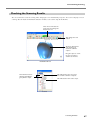
Checking the Scanning Results
You can examine the results of scanning while changing the view method and perspective. The Scan List displays a list of
scanning data. For detailed information about this window, see the online help for Dr. PICZA3.
These move and rotate the
perspective, and change the
amount of zoom.
This changes the view
method.
The three-dimensional
item that has been
scanned is called the
"object."
Drag the object to orient
the area you want to
examine to the front.
Dr.PICZA3 Window
This indicates the name of a group
that contains a number of objects.
This switches between
showing and hiding the
group and the object.
This indicates the name of the object.
Scan list
3. Creating 3D Data
37
3-4 Finishing the Data
You take the data from basic scanning and modify it to produce finished data that has the form you want.
Selecting and Scanning a Specific Area
After the basic scanning, you can select specific areas and performing additional scanning (rescanning). The available types
of rescanning are as follows.
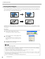
Rescan
You use rescanning when you want to increase the number of measuring points (scan points) and enhance the degree of
completion of the 3D data.
Perform coarse scanning of
the entire object.
Rescan required
areas in detail.
You can reproduce detailed
surface patterns.
...you rescan just
these areas.
Even when holes are present...
The holes are sealed, yielding the
same shape as the original!
Line Scan/Point Scan
You use line scanning and point scanning when you want line-segment or point data to serve as supplemental data for
three-dimensional modeling operations using CAD or computer-graphics programs.
38
Perform line scanning with Dr.
PICZA3...
...and re-create the
curved surfaces with the
3D CAD program!
Perform point scanning with Dr.
PICZA3...
...and re-create the
curves with the 3D CAD
program!
3. Creating 3D Data
3-4 Finishing the Data
Scanning Modes for Rescanning
You can choose the same scanning modes for rescanning and line scanning as you can for basic scanning.
• Scanning using plane scanning -• Scanning using rotary scanning --
Plane rescan and plane line scan
Rotary rescan and rotary line scan
What follows is a general guide for using these selectively.
Rescan
• When you’re rescanning areas that could not be scanned
Normally you choose plane rescanning. When the scan object has a complex shape, it may be a good idea to use plane
rescanning to perform overlapping scanning, changing the angle between each scanning pass.
Note, however, that rescanning is not effective in cases where the laser beam cannot reach the area or the reflected
laser beam does not reach the sensor from any angle.
• When you’re rescanning a specific area at a fine scanning pitch
It may be a good idea to perform rescanning in the same mode you used for the basic scanning.
When you want to perform fine-detail scanning of the surface pattern of a scan object whose shape is cylindrical or
close to cylindrical, you first perform coarse rotary scanning, then choose rotary rescanning.
Line Scan
Normally you choose the same mode you used for basic scanning. However, when you want to scan line segments that
wrap around to the back of the object, you choose rotary line scanning. Plane line scanning can scan only line segments on the surface visible in the window.
The entire circumference
can be scanned.
Rotary line scan
Only the line segment shown by
the thick line can be scanned.
Plane line scan
To Use the Data with a 3D CAD Program or the Like
To use line-segment and point data as supplementary data for a 3D CAD program, you may need to export the data and
convert the file.
☞ See "3-5 Saving and Exporting Data."
3. Creating 3D Data
39
3-4 Finishing the Data
Procedure
You perform rescanning using the following procedure. The screens shown are those for plane rescanning.
1
First, scan the entire object.
Choose a scanning mode according to the shape of
the scan object.
From this point on, never open the door until rescanning
ends. Doing so switches off the power. Scanning cannot
be resumed when you then switch on the power again.
Shortening the Scanning Time by Performing
Basic Scanning at a Coarse Pitch
You can speed up operations during basic scanning
by scanning at a coarse pitch. For line scanning and
point scanning in particular, it is a good idea to scan
at the minimum pitch necessary to get the general
shape.
2
When the scan of the entire object finished, click
the [
] button to choose the method you want
to use for rescanning.
3
Drag to specify the rescanning area.
You can specify more than one rescanning area.
Shortcut Keys for Shifting the Perspective
• To Rotate the Object
Hold down the SPACE key and drag
• To Move the Object
Hold down the Ctrl key and drag
• To expand and reduce the Object
Hold down the shift key and drag
SPACE key + drag left or right to shift the
perspective.
In addition to these shortcuts, you can also shift the
perspective using the arrow keys.
Delineating Areas That Need Rescanning
You can remove improper surfaces that shouldn't exist and clearly delineate areas that need to be
rescanned.
Before you specify a rescanning area, clicking the [
] button displays the "Delete Abnormal Faces"
dialog box. Running this command deletes, for example, the abnormal surface produced on the handle
of the cup shown in the figure at right.
For detailed information about this, refer to the online
help for Dr. PICZA3.
40
3. Creating 3D Data
Drag to specify the rescanning
area.
3-4 Finishing the Data
4
Click the [
5
Drag to verify the area to rescan.
] button.
The mode for specifying the rescanning area is canceled.
The specified rescanning area is displayed as a threedimensional form.
When You Want to Respecify the Rescanning Area
Go back to step 2 on the previous page, then click
anywhere on the object to clear the specified area.
Specified rescanning area
6
Click the [
] button.
7
If necessary, change the scanning pitch, then click
[Scan].
The [Settings for Scanning] dialog box appears.
Here, none of the settings except for the scanning pitch
can be changed. It is also not possible to set a different scanning pitch for each area.
Rescanning
area
Setting the Scanning Pitch
When performing rescanning, make the setting for the
scanning pitch as fine as possible. This increases the
number of scanning points, enhancing the degree of
completion. When little free memory is available, it
may be a good idea to use a narrow scanning area
and perform rescanning in several passes.
These set
scanning pitch.
This executes
rescanning.
You can perform rescanning as many times as you like after basic scanning. Also, when you want to redo scanning after
checking the scanning results, you can go back to the previous state before rescanning by clicking the [
] button.
For detailed information on rescanning methods, refer to the online help for Dr. PICZA3.
3. Creating 3D Data
41
3-4 Finishing the Data
Creating New Polygons
You can create new polygons using all the scanning points, including the data produced by rescanning. These polygons are
called a "polygon mesh." Creating a polygon mesh can make it possible for you to reproduce cavities and voids in the
object and fill in holes according to the surrounding shape.
Creating a polygon mesh for
area of connected voids...
...deletes surfaces, reproducing the
void area of the original!
Creating a polygon mesh when a
hole has occurred ...
...lets you fill in the hole
simply and easily!
A polygon mesh is composed of polygons created by estimating the original shape of the scan object from the scanning
points. They differ from the polygons displayed immediately after scanning, which are generated simply by connecting the
scanning points.
Procedure
1
Click the [Create Polygon Mesh...] button.
The [Polygonization Options] dialog box appears.
[Create Polygon Mesh...] button
2
Select the parameters for creating a polygon mesh,
then click [OK].
For detailed information on the [Polygonization Options] dialog box, refer to the online help for Dr.
PICZA3.
3
If the polygon mesh is not what was intended, change
the parameters and create it again.
Tips for Creating a Polygon Mesh
To create a polygon mesh having a high degree of completion, you may need to scan at as fine a pitch as possible in
order to increase the number of scanning points. In particular, cases like those described below may yield a polygon
mesh having a configuration that is not what you intended.
• When there is a small number of scanning points with respect to undulations in the scan object
• When areas with holes are too big or the shape of them is complex
In such cases, rescan just that area at a fine pitch. When little memory is available on the computer, it may be a good
idea to divide the area into parts and repeat rescanning several times to increase the number of scanning points
sufficiently, and then create the polygon mesh.
☞ Go to "3-4 Finishing Data," see "Selecting and Scanning a Specific Area."
42
3. Creating 3D Data
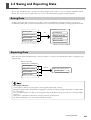
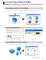
3-5 Saving and Exporting Data
You can take data obtained by scanning and creating polygon meshes and save it in a file format compatible with Dr.
PICZA3. You can also convert (export) data and save it in a file format allowing import into other programs.
Saving Data
Go to the [File] menu and click [Save As]. The data is saved in Dr. PICZA project format (with the file extension .pij).
In addition to working with saved files with Dr. PICZA3, you can edit them using 3D Editor, an editing program for 3D data.
Dr.PICZA project format
Scanning data
Save
Scanning data
Polygon-mesh data
Polygon-mesh data
Line-scan data
Line-scan data
Point-scan data
Point-scan data
All data is saved in a single file.
Exporting Data
When you want to take data obtained by scanning and make use it with a 3D CAD program or other such program, you
export the data.
Choose some data.
Scanning data
Export
Polygon-mesh data
Line-scan data
DXF format, STL format etc.
Scanning data
Point-scan data
About Exportable Data
Scanning data is data for measuring points (scanning points) obtained by scanning.
Polygon-mesh data is data composed of new polygons created by estimating the proper shape of the scan object from
the scanning data.
Line-scan data and point scan data are measuring-point data newly obtained respectively by line scanning and point
scanning.
However, the exportable file formats for each type of data are predetermined.
For detailed information, refer to the online help for Dr. PICZA3.
3. Creating 3D Data
43
3-5 Saving and Exporting Data
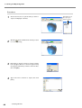
Procedure
44
1
At the Scan List, choose just the data you want to
export and display the window.
2
Click the [ ] button. Click the file format you want
to use for exporting.
3
Depending on the file format you clicked, a dialog
box may appear. Choose a selection supported by
the program with which you want to share the data,
then click [OK].
4
Type in the name of the file to export, then click
[Save].
3. Creating 3D Data
Check the box of
the object you
want to export.
4. Editing Scanning Results Using 3D Editor
This chapter describes the basic methods of operation for 3D Editor, the 3Ddata editing program included with the machine.
45
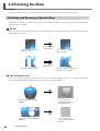
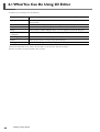
4-1 What You Can Do Using 3D Editor
3D Editor lets you do things like the following.
Enlarge and reduce
Deforming operations such as stretching in one direction are also possible.
Move and rotate
Specifying numerical values for the movement distance and angle of rotation is
also possible.
Sever
You can divide an object into parts. Filling cut surfaces is also possible.
Delete
You can delete unneeded objects.
Merge
You can unite a number of objects. There is even an alignment feature for doing this.
Reduce the number
of polygons
This reduces the amount of data while keeping detail.
Smoothing feature
This smooths the surfaces of objects.
Export
Data can be saved in a wide variety of file formats.
Repolygonization
This creates a polygon mesh by using imported data.
For detailed information on the features of 3D Editor, refer to the online help for 3D Editor.
Note that 3D Editor can only work with surface models.
46
4. Editing Scanning Results
4-2 Importing and Exporting Data
This section describes how to import and export data using 3D Editor.
Importing Scanning Results Immediately
In Dr. PICZA3, clicking the [Run 3D Editor] button starts 3D Editor and simultaneously imports the displayed scanning
results.
[Run 3D Editor] button
Dr.PICZA3
3D Editor starts and data is imported.
Importing and Exporting
Clicking the [Import] button lets you import files in Dr. PICZA
project format, DXF format, and so on.
Clicking the [Export] button lets you save data in a wide variety of file formats that are useful for creating 3D CAD data and
3D computer graphics.
[Import] button
[Export] button
3D Editor also supports importing for PIX-format
files from Dr. PICZA versions 1 through 2.
Importing More Than One Set of Data
You can use the [Import] button to import more than one set of data and place a number of objects in the 3D Editor window.
4. Editing Scanning Results
47
4-3 Basic Operations for Objects
This section describes the windows in 3D Editor and how to perform simple editing using the program.
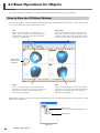
How to View the 3D Editor Window
The 3D Editor window is composed of panels that display the object from four different perspectives at the same time. You
can carry out editing tasks using any one of these views.
Top
This is a view of the object seen from directly
above. You use it at times such as when you want
to move only in the X or Y direction. Z-direction
movement is not possible.
Perspective
You use this when you want to view the overall
shape. You can move in all three directions (X, Y,
and Z), but it does not let you gauge the direction
or distance of such movement with any accuracy.
This indicates
the X, Y, and Z
orientation.
Front
This is a view of the object seen from directly in
front. You use it at times such as when you want to
move only in the X or Z direction. Y-direction
movement is not possible.
Side
This is a view of the object seen directly from the
side. You use it at times such as when you want to
move only in the Y or Z direction. X-direction
movement is not possible.
Imported objects appear in the Object List. You can perform tasks such as displaying only the objects you want to view and
deleting unneeded objects.
Group name
This is a collection of multiple objects.
Object name
Object List
48
4. Editing Scanning Results
4-3 Basic Operations for Objects
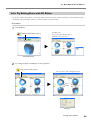
Let's Try Editing Data with 3D Editor
Let's try some simple editing. We'll scan an apple with the machine, then try cutting and moving it. The explanations in this
section begin at the point where you have scanned an apple using Dr. PICZA3.
Procedure
1
Start 3D Editor.
Click the [Run 3D Editor] button.
3D Editor starts.
The scanning data for the apple is
imported at the same time.
Dr.PICZA3 Window
2
Try cutting the apple vertically. First, do the preparation.
Click the [Cut at Plane] button.
The cut surface and a dialog box appear.
Cut
surface
Dialog box
4. Editing Scanning Results
49
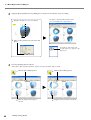
4-3 Basic Operations for Objects
3
Using the [Front] window, let's try shifting the cut surface to the left, then carry out cutting.
1
Drag the cut surface to move it to the left.
2
When you have decided on the cut location, click
[Run].
The apple is divided into two parts. However, its still looks like a single object.
New objects with names like
[Cut-0] and [Cut-1] appear in the
Object List.
4
50
Let's try separating the two objects.
When you're done with the operation, right-click to quit the [Move Object] mode.
1
Click the [Select Object] button.
3
Click the [Move Object] button.
2
Click the left part of the apple to
select it.
4
Drag the portion you selected to the left.
4. Editing Scanning Results
4-3 Basic Operations for Objects
5
Now try orienting the cut surface of the apple on the right to face the front.
You can only do this when you're in the [Top] window.
When you're done with the operation, right-click to quit the [Move Object] mode.
6
1
Click the [Select Object] button.
2
Click the right side of the
apple to select it.
3
Click the [Rotate Object] button.
4
Drag to turn the object counterclockwise.
Look at the [Perspective]
window to see how the cut
surface faces the front.
Finally, let's try deleting the cut-off object.
This operation can be carried out from any perspective except [Side].
1
Click the [Select Object] button.
The cut-off portion is deleted.
2
Click the cut-off portion to select it.
3
Click the [Erase] button.
When you view the Object
List, you see that [Cut-0] has
been deleted.
4. Editing Scanning Results
51
52
5.What to Do If...
This section describes how to resolve problems that can occur during operation, and what is required when moving the machine to a different location.
53
5-1 What to Do If...
The power doesn't come on or go off.
The message "COM:** not ready" appears on the
computer.
The power doesn't come on.
Are the AC adapter and the power cord connected correctly?
•Connect the AC adapter and power cord securely so that
they do not come loose.
• Unplug the AC adapter from the electrical outlet, then plug
it in again.
Is the door open?
Close the door. The power does not come on while the door is
open.
The power is not switched off when the door is opened.
Is a foreign object caught in the interlock switch?
Remove the foreign object.
Is the machine powered up?
Be sure to turn on the machine before you run Dr. PICZA3.
Is the number for the communication port set correctly?
In Dr. PICZA3, go to [Preferences] and make sure the number
for the communication port is set correctly.
Are you using a lengthy USB cable or a USB hub?
Use the included USB cable. Never use a USB hub or the like.
After you have checked the matters just described, if scanning is still not possible, then take action as follows.
1. Switch off the power.
2. Unplug the AC adapter from the electrical outlet, then plug
it in again.
3. Restart the computer.
4. Switch on the power.
Scanning is impossible.
The power button illuminates or flashes red.
Is the head retainer still attached?
Be sure to remove the head retainer before you turn on the
power.
Is anything placed on some internal location other than
the table?
Remove whatever has been placed.
The power button flashes red and blue.
Is the cable connected?
Connect the cable securely.
Are you using a lengthy USB cable or a USB hub?
Use the included USB cable. Never use a USB hub or the like.
The power button illuminates red and blue.
Open the door, then close the door and turn on the machine
again.
• About the illumination pattern of the power button
☞Go to "1-2 Names and Functions," see "About the Indicator
Lights."
The message "Cannot communicate with present
scanner" appears on the computer.
Is the number for the communication port set correctly?
In Dr. PICZA3, go to [Preferences] and make sure the number
for the communication port is set correctly.
Other Symptoms
Scanning ended, but the computer then stopped.
Does the computer have enough memory?
Go to Dr. PICZA3's [Settings for Scanning] dialog box and
check how much memory is required, then increase the scanning pitch. Alternatively, consider installing more memory.
When scanning exceeds the amount of free memory on the
computer, the operation of the computer may become very
slow.
The message "Can't find MODELA Player" or
"Can't find 3D Engrave" appears on the computer.
The buttons for running these do not function on this system.
They become available when you are using it together with
the MODELA series or the like.
Uninstalling the driver
Remove [Roland LPX-600 USB Device 1.1] from the list of
[Add or Remove Programs] (or [Add/Remove Programs]).
☞See the next section "What to Do If Installation Is Impossible."
What to Do If Installation Is Impossible
If installation quits partway through, or if the wizard does not
appear when you connect the USB cable, take action as follows.
☞See "2-4 Installing and Setting Up the Software."
Continued on the next page
54
5. What to Do If...
5-1 What to Do If...
1. If the [Found New Hardware Wizard] dialog appears,
click [Finish] to close it.
3. Delete [LPX-600].
Windows XP/2000
2. Display [Add or Remove Programs] (or [Add/Remove
Programs]).
Windows XP
From the [Start] menu, choose [Control Panel], then click
[Add or Remove Programs].
1
Double-click [Universal Serial Bus controllers].
Windows 2000/Me/98 SE
From the [Start] menu, choose [Settings], then [Control
Panel], then click [Add/Remove Programs].
2
Click [LPX-600].
3
Click [View], then
click [Uninstall].
4
Click [OK].
1
Click [LPX-600].
2
Click [OK].
3
Click [OK].
3. Uninstall [Roland LPX-600 USB Device 1.1].
1
Click [Change/Remove].
Windows Me/98 SE
2
3
Click [Continue].
Click [Finish].
4. Detach the USB cable connected to the computer.
5. Restart Windows.
6. Follow the procedure in "Installing the Driver" to redo
installation from the beginning.
☞Go to "2-4 Installing and Setting Up the Software," see "Installing the Driver."
If [Roland LPX-600 USB Device 1.1] does not appear in the list,
follow the steps below.
1. Display [System Properties].
Windows XP
Click the [Start] menu, then right-click [My Computer].
Click [Properties].
Windows 2000/Me/98 SE
Right-click [My Computer] on the desktop. Click [Properties].
4. Close the [Device Manager] dialog and click [OK].
5. Detach the USB cable connected to the computer.
2. Display [Device Manager].
Windows XP/2000
6. Restart Windows.
1
Click the [Hardware] tab.
2
Click [Device Manager].
7. Follow the procedure in "Installing the Driver" to redo
installation from the beginning.
☞See "2-4 Installing and Setting Up the Software."
Windows Me/98 SE
Click [Device Manager].
5. What to Do If...
55
5-2 When Moving the Machine
When you move the machine to another location, you secure the table and the head in place using screws.
Procedure
1
Make sure the power to the machine is turned off, then detach the AC adapter, the USB cable, and the power
cord.
2
Remove the AC adapter holder.
You use the screws you removed to secure the head in place.
AC adaptor holder
Screws
The back of the machine
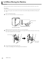
3
Open the door, then move the head to where it is to be secured in place.
Refrain from touching anything outside the shaded area in the figure below. Improperly moving the head or touching
other internal components may cause breakdown.
Press down gently.
Press in until it
stops moving.
4
56
Secure the table and head in place with screws.
☞ Go to "2-2 Installing" and see "Removing the Protective Material."
5. What to Do If...
6. Appendix
57
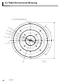
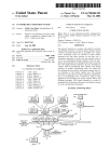
6-1 Table Dimensional Drawing
20 screw holes (M6, depth 7 mm)
70
110
45º
150
254
190
45º
230
1/2 scale
(Unit: mm)
58
6. Appendix
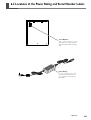
6-2 Locations of the Power Rating and Serial Number Labels
Serial Number
This is require when you seek
maintenance, servicing, or support.
Never peel off the label or let it get
dirty.
Power Rating
Use an electrical outlet that
meets the requirements for voltage, frequency, and amperage
given here.
6. Appendix
59
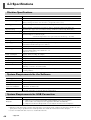
6-3 Specifications
Machine Specifications
LPX-600
Table size
Diameter 254 mm (10 in.)
Maximum scanning area
Plane scanning: Width 254 mm (10 in.), height 406.4 mm (16 in.)
Rotary scanning: Diameter 254 mm (10 in.), height 406.4 mm (16 in.)
Scanning pitch
Plane scanning: width direction 0.2 to 254 mm, height direction 0.2 to 406.4 mm
Rotary scanning: circumference 0.18 to 3.6 degrees, height direction 0.2 to 406.4 mm
Repeat accuracy
±0.05mm (This figure reflects standard scanning conditions established by Roland DG.)
Maximum table load weight 5 kg
Laser
Wavelength: 645 to 660 nm
Maximum output: less than 0.39 µW
(maximum output of the laser light emitted inside housing is 0.1 mW)
Sensor
Noncontact laser sensor
Scanning method
Spot-beam triangulation
Operating speed
Table rotation speed: 9 rpm, head rotation speed: 4.48 rpm,
maximum head movement speed: 37 mm/sec.
Interface
USB (compliant with Universal Serial Bus Specification Revision 1.1)
Power supply
Dedicated AC adapter
Input: AC 100 to 240 V ±10% 50/60 Hz 1.7 A
Output: DC 19 V, 2.1 A
Power consumption
Approx. 20 W (including AC adapter)
Dimensions
630 [W] x 506 [D] x 761 [H] mm (24-13/16 [W] x 19-15/16 [D] x 29-15/16 [H] in.)
Weight
63 kg (139 lb.)
Packed dimensions
830 [W] x 710 [D] x 1050 [H] mm (32-3/4 [W] x 28 [D] x 41-3/8 [H] in.)
Packed weight
83 kg (183 lb.)
Environment
Temperature: 10 to 40ºC (50 to 104ºF) (25ºC [77ºF] or more recommended)
Humidity: 35 to 80% (no condensation)
Included items
AC adapter, power cord, AC adapter holder, cable clamps, USB cable, CD-ROM, clay, user's manual,
scanning software
System Requirements for the Software
Operating system
Windows XP/2000/Me/98 SE (Second Edition)
CPU
Pentium 4 processor or better recommended
Memory
512 MB or more recommended
Free hard-disk space
required for installation
Dr.PICZA3: 20 MB or more
3D Editor: 10 MB or more
Display
800 x 600 resolution and 16 bit colors (High color) or more recommended.
OpenGL-compatible accelerator board recommended.
System Requirements for USB Connection
Operating system
Windows XP/2000/Me/98 SE (Second Edition)
Computer
1) Computers preinstalled with Windows 98/Me/2000/XP at the time of purchase
(This includes such computers later upgraded to Windows Me/2000/XP.)
2) Computers on which USB operation is assured by the manufacturer of computers
• Whether a USB connection is possible depends on the specifications of the computer. To determine whether the computer you're using is capable of correct USB operation, check with the manufacturer of the computer.
• Use the included USB cable. Never use a USB hub or the like.
60
6. Appendix
Please read this agreement before opening the sealed disk package
Opening the sealed disk package implies your acceptance of the terms and conditions of this agreement.
Roland License Agreement
Roland DG Corporation ("Roland") grants you a non-assignable and non-exclusive right to use the COMPUTER
PROGRAMS in the disk package ("Software") under this agreement with the following terms and conditions.
1. Coming into Force
This agreement comes into force when you purchase and open the sealed disk package. The effective date of this
agreement is the date when you open the sealed disk package.
2. Property
Copyright and property of this Software, logo, name, manual and all literature for this Software belong to Roland
and its licenser. The followings are prohibited:
Unauthorized copying the Software or any of its support file, program module or literature.
Reverse engineering, disassembling, decompiling or any other attempt to discover the source code of the Software.
3. Bounds of License
Roland does not grant you to sub-license, rent, assign or transfer the right granted under this agreement nor the
Software itself (including the accompanying items) to any third party.
You may not provide use of the Software through time-sharing service and/or network system to any third party
who is not individually licensed to use this Software.
You may use the Software by one person with using a single computer in which the Software is installed.
4. Reproduction
You may make one copy of the Software only for back-up purpose. The property of the copied Software belongs
to Roland.
You may install the Software into the hard disk of a single computer.
5. Cancellation
Roland retains the right to terminate this agreement without notice immediately when any of followings occurs:
When you violate any article of this agreement.
When you make any serious breach of faith regarding this agreement.
6. Limitations on Liability
Roland may change the specifications of this Software or its material without notice.
Roland shall not be liable for any damage that may caused by the use of the Software or by exercise of the right
licensed by this agreement.
7. Governing Law
This agreement is governed by the laws of Japan, and the parties shall submit to the exclusive jurisdiction of the
Japanese Court.
1000000174
R1-050725