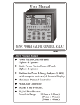
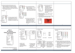
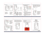
1
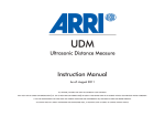
544Z REGULAR CAMERA USER MANUAL 960H Ultra Resolution Series It’s recommended to use this camera with a DVR which supports 960H video recording. Please read the instructions thoroughly before using the product. FEATURES 1. 1/3" HR Color CCD 2. 700 TVL superior image quality 3. Further camera parameters configuration via its own OSD 4. Multilingual on-screen display menu in 4 languages (English / French / Portuguese / Spanish) 5. Built-in microphone for audio recording PACKAGE CONTENT ‧ Camera x 1 ‧ User manual x 1 ‧ Wrench x 1 SPECIFICATION* Pick up Element 1/3" HR color CCD image sensor Number of Pixel 976(H) x 494(V) <NTSC> / 976(H) x 582(V) <PAL> Resolution 700 TVL Minimum Illumination 0.1 Lux / F2.0 S/N Ratio More than 48dB (AGC off) Electronic Shutter AUTO: 1/50 (60) to 1/100,000 sec. MANUAL: 1/50(60), FL 1/120(100), 1/250, 1/500, 1/1,000, 1/2,000, 1/5,000, 1/10,000, 1/20,000, 1/50,000, 1/100,000 sec. Lens Mount IRIS Mode White Balance Gain Control CS Mount AES / VD / DD Auto / Fixed AGC adjustable / Fixed Sharpness Adjustable BLC ON / OFF Digital WDR YES Video Output 1.0 Vp-p composite, 75Ω Microphone Built-in Power Source (±10%) DC 12V Current Consumption(±10%) Dimensions (mm)** * The specifications are subject to change without notice. 70mA 117(L) x 60(W) x 50(H) ** Dimensional Tolerance: ± 5mm 151_V0.9 MAJOR OPERATING CONTROL AND FUNCTIONS 1. Flange Back Adjusting Ring It is suitable for CS-mount lens. When using C-mount lens, please use the CS-C conversion ring*. 2. Back Focal Lock Hexagonal Bolt The camera is set at the standard back focal position. Fine-tuning is inevitable according to the lens types. Adjust the lens back-focus by turning the focusing knob. 3. Auto Iris Lens Connector Supplies power and controls signals to an Auto Iris Lens. 4. Power LED Indicator The Power LED Indicator indicates normal status during operation. 5. Power Input Terminal ! For connecting to DC12V regulated power supply. 6. Video Output Connector (VIDEO OUT) For connecting to CCTV monitor video input with coaxial cable. 7. V.D. / D.D. selectable When using Auto Iris Lens, select Video Drive or Direct Drive depend on the type of lens you used. 8. Audio Output Connector (AUDIO OUT) Connect to the AUDIO IN connector of the recording device. 9. OSD Menu Selection For more details, please refer to “CAMERA PARAMETERS”. INSTALLATION *** It is recommended to have the following installation done by the qualified service personnel or system installer. *** 1. Mount a lens onto the camera (By turning it clockwise). It is suitable for CS-mount lens. But if the lens you chose is C-mount, please use the CS-C conversion ring* to connect the C-mount lens and the camera. 2. Switch the lens selection depending on the lens you used. * Auto iris lens: V.D. / D.D.: Select VD or DD depend on the type of lens you used. 3. 4. 5. 6. Connect the camera VIDEO output and the monitor video input with a 75Ω coaxial cable. Connect the camera AUDIO output and the monitor audio input with a coaxial cable. Connect the POWER terminal of the camera to a right power supply. Adjust the focus or flange-back (Please refer to NOTE for adjustment instructions). * The CS-C conversion ring is not supplied in the sales package and needs to be purchased separately. NOTE: Focus or Flange-Back Ring Adjustment 1. Mount the lens by turning it clockwise on the lens mount of the camera. 2. Loosen the screws on the flange-back adjusting ring. 3. Turn the flange-back adjusting ring to the desired position. 4. Tighten the screws on the flange-back adjusting ring. Flange Back Adjusting Ring Back focal lock hexagonal bolt PRECAUTIONS Do not install the camera in an environment where the humidity or temperature is high Do not install the camera under the unstable lighting condition Do not expose the camera to rain or moisture Do not keep the camera face to strong light directly Do not touch the front glass of the camera Do not use other than specified power source Do not disassemble the camera CAMERA PARAMETERS There are five buttons on the camera rear panel for users to further configure camera parameters. If you want to … Press … Enter the camera configuration menu MENU Move to the sub-menu you want ↑ / ↓ Change setting Enter the configuration page of an option ← / → ENTER Menu Tree For options with , press the button “ ” (Enter) to enter their respective setting pages. SUB-MENU OPTIONS LANGUAGE LANGUAGE ENGLISH / PORTUGUÊS / ESPAÑOL / FRANCÊS OSD COLOR WHITE / YELLOW / CYAN / GREEN / MAGENTA / RED / BLUE / BLACK ID SET (POSITION) OFF / TOP / BOTTOM CAMERA ID REMARK ID NO EXPOSURE IMAGE LENS MANUAL / DC BLC OFF / PAT 1 / PAT2 GAIN CONTROL AUTO-H / AUTO-M / AUTO-L / -3 ~ 36dB SHUTTER (1/N) AUTO / 60(50) / 100(120) / 250 / 500 / 1000 / 2000 / 5000 / 10000 / 20000 / 50000 / 100000 BRIGHTNESS CONTRAST CHROMA GAIN SHARPNESS NOISE REDUCTION WHITE BALANCE ON / OFF SUB-MENU OPTIONS REMARK FUNCTION MIRROR ON / OFF FLICKERLESS ON / OFF DAY NIGHT Not available BLEMISH COMP D-WDR ON / OFF HLC ON / OFF WINDOW PRIVACY MASK Not available MASK NUMBER 1~8 MASK TYPE OFF / FULL / HALF MASK SET COLOR MOTION DETECT 1~8 MOTION DETECT Not available ALERT (TIME) SENSTIVITY PIN OUTPUT DISPLAY COLOR IGNORE AREA CAUTION RISK OF ELECTRIC SHOCK CAUTION: To reduce the risk of electric shock, do not expose this apparatus to rain or moisture. Only operate this apparatus from the type of power source indicated on the label. The company shall not be liable for any damages arising out of any improper use, even if we have been advised of the possibility of such damages. The lightning flash with arrowhead symbol, within an equilateral triangle, is intended to alert the user to the presence of uninsulated “dangerous voltage” within the product’s enclosure that may be of sufficient magnitude to constitute a risk of electric shock to persons. This exclamation point within an equilateral triangle is intended to alert the user to the presence of important operating and maintenance (servicing) instructions in the literature accompanying the appliance. ROHS Announcement All lead-free products offered by the company comply with the requirements of the European law on the Restriction of Hazardous Substances (RoHS) directive, which means our manufacture processes and products are strictly “lead-free” and without the hazardous substances cited in the directive. The crossed-out wheeled bin mark symbolizes that within the European Union the product must be collected separately at the product end-of-life. This applies to your product and any peripherals marked with this symbol. Do not dispose of these products as unsorted municipal waste. CE Mark This apparatus is manufactured to comply with the radio interference. The company does not warrant that this manual will be uninterrupted or error-free. We reserve the right to revise or remove any content in this manual at any time.