1
USER MANUAL FOR
EXPLOSION PROOF EMERGENCY LIGHT
FITTING type FLXE 118 LED
d.o.o.
10090 Zagreb, Medarska 69
tel. 049 222900, fax 049 426450
e-mail: [email protected]
www.tepex.hr
No: TEPEx.RS.016
Rev : 0
Date: 11.2012.
B - emergency light fitting with main power supply option and automaticall turn ON after power return option
C - emergency light fitting with RESET function
D - emergency light fitting for use in areas with special hazards
180 - emergency light fitting with autonomy of 3 hours
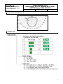
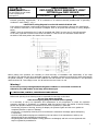
8. DIMENSION
330
240±1
12
220±1
160±0,5
180±0,5
O13
9. MOUNTING
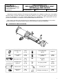
Fixing dimensions are shown in article 8. Light fitting is suitable for ceiling, wall or pole mounting, the
accessories are not included, see table in article 12. for the correct selection of the mounting accessories
and article 6. for self-adhesive pictograms.
Ex d cable glands and plugs are not an part of the delivery for the types FLXE LED 118/0. and FLXE LED
118/1.
Light fitting with TEST and RESET function must be equipped with two Ex d cable glands or two Ex de
adapter type ADP 24.
Light fitting type FLXE 118 LED/2. and FLXE 118 LED/3. is provided with one or two Ex de adapter.
Warning: Over tightening might damage the light fitting.
In case of use in an extremely aggressive atmosphere, please consult to the manufacturer.
The laight fitting is for functional reasons supplied with partially screwed cover. After mounting
and before putting the light fitting into operation, the cover must be fully screwed with the
enclosure and mechanically blocked with screw M5x10 (ISO 4027).
After opening the laight fitting, threded surfaca on cover and enclosure should be protected by
protective means for threads.
10. INSTALLING AND PUTTING INTO OPERATION
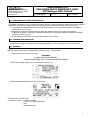
Network connection have to be performed through screwless terminals located on the LED module FLXE 10130 according to wiring diagram and technical data:
Maintained:
Permanent line has to be connected to the L(1) terminal. Phase conductor for power supply has to be
connected through installation switch to the L'(4) terminal. One should be careful that phase L and L' are the
same phase. Neutral conductor has to be connected to the N(3) terminal and protective earth conductor to
the PE(2) terminal.
Non maintained:
Permanent line has to be connected to the L(1) terminal. Neutral conductor has to be connected to the N(3)
terminal and protective earth conductor to the PE(2) terminal. L'(4) terminal is not connected.
5