1
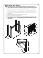
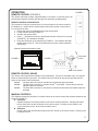
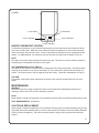
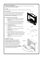
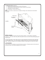
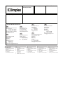
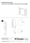
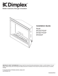
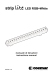
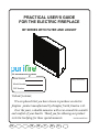
PRACTICAL USER’S GUIDE
FOR THE ELECTRIC FIREPLACE
BF SERIES WITH FILTER AND LOGSET
Serial Number
Quality checked by:
Model Number
CAT Number
Valued Customer,
We are pleased that you have chosen to purchase an electric
fireplace product manufactured by Dimplex North America Ltd.
Over the years, valuable memories will occur around the warmth
and comfort of your hearth. Thank you for allowing our product
7207920100REV04
to be the backdrop for those special moments.
EU
FR
ES
IT
DE
PL
QUICK REFERENCE GUIDE
1.
Prior to the first use of the fireplace verify the following:
• Are the circuit breakers for the fireplace on?
• Are the light bulbs in your fireplace loose? (to check, follow the
instructions for replacing the light bulbs under the Maintenance
section of this manual)
2.
The heater on your fireplace may emit a slight, harmless odor when
first used. This odor is a normal condition caused by the initial
heating of internal heater parts and will not occur again.
3.
If your heater does not emit heat, ensure the main switch is on, the
built-in thermostat is set above the current room temperature and any
wall switches for the unit are on. If this does not work, switch the unit
off for 5 minutes and try again. Consult operation section of your
practical users guide for further information.
4.
The information regarding the model of your fireplace can be found
on the rating plate located on the side adjacent to the supply cord.
5.
If you have any technical questions regarding the operation of your
fireplace, or require service for your fireplace contact customer
service.
CONTENTS
PAGE 1
Important Instructions
PAGE 2
Model and Serial Number Information
PAGE 3
Installation
PAGE 5
Operation
PAGE 6
Maintenance
PAGE 9
Warranty
IMPORTANT INSTRUCTIONS
PLEASE RETAIN THIS USER’S GUIDE FOR FUTURE REFERENCE
When using electrical appliances, basic precautions should always be followed to reduce the risk of fire,
electric shock, and injury to persons, including the following:
1. Read all instructions before using the electric fireplace.
2. This fireplace is hot when in use. To avoid burns, do not let bare skin touch hot surfaces. The trim
around the heater outlet becomes hot during heater operation. Keep combustible materials, such as
furniture, pillows, bedding, papers, clothes, and curtains at least 0.9 meters from the front of the unit.
3. Extreme caution is necessary when any heater is used by or near children or invalids and whenever
the unit is left operating and unattended.
4. Young children should be supervised to ensure that they do not play with the appliance.
5. The appliance is not intended for use by young children or infirmed persons unless they have been
adequately supervised by a responsible person to ensure they can use the appliance safely.
6. The appliance must be positioned so that the plug is accessible.
7. Always unplug the electric fireplace when not in use.
8. If the supply cord is damaged, it must be replaced by the manufacturer, or its service agent, or a
qualified person in order to avoid a hazard.
9. Do not operate any unit with a damaged cord or plug, or if the heater has malfunctioned, or if the
electric fireplace has been dropped or damaged in any manner. Return heater to authorized service
facility for examination, electrical or mechanical adjustment, or repair.
10. Do not use outdoors.
11. Do not use this fireplace in the immediate surroundings of a bath, a shower or a swimming pool.
12. Do not install the fireplace directly on carpet or a similar surface which may restrict air circulation
beneath the unit.
13. Do not run the cord under carpeting. Do not cover cord with throw rugs, runners, or the like.
Arrange cord away from traffic area and where it will not be tripped over.
14. Do not locate the heater immediately below a fixed socket-outlet.
15. Do not locate the appliance in front of a fixed socket-outlet
16. To disconnect the fireplace, turn the controls off, then remove the plug from the outlet.
17. Do not insert or allow foreign objects to enter any ventilation or exhaust opening as this may cause an
electric shock or fire, or damage to the heater.
18. To prevent a possible fire, do not block air intake or exhaust in any manner. Do not use on soft
surfaces, like a bed, where openings may become blocked.
19. All electrical heaters have hot and arching or sparking parts inside. Do not use in areas where
gasoline, paint, or flammable liquids are used or stored or where the unit will be exposed to
flammable vapors.
20. Do not modify the electric fireplace. Use it only as described in this manual. Any other use not
recommended by the manufacturer may cause fire, electric shock or injury to persons.
21. Avoid the use of an extension cord. Extension cords may overheat and cause a risk of fire. If you
must use an extension cord, the cord must be 3-core type and have a rating no less than 13 amps.
22. Do not burn wood or other materials in the electric fireplace.
23. Do not strike the fireplace glass.
24. Always use a certified electrician should new circuits or outlets be required.
25. Always use properly grounded, and fused outlets.
26. Disconnect all power supply before performing any cleaning, maintenance or relocation of the unit.
27. When transporting or storing the unit and cord, keep in a dry place, free from excessive vibration and
store so as to avoid damage.
28. WARNING: In order to avoid overheating, do not cover the heater
29. CAUTION: In order to avoid a hazard due to the inadvertent resetting of the thermal cutout, this
appliance must not be supplied through an external switching device, such as a timer, or connected
to a circuit that is regularly switched on and off by the utility
SAVE THESE INSTRUCTIONS
1
NOTE: Procedures and techniques that are considered important enough to emphasize.
CAUTION: Procedures and techniques which, if not carefully followed, will result in damage to the
equipment.
WARNING: Procedures and techniques which, if not carefully followed, will expose the user to the risk of
fire, serious injury, illness or death.
MODEL AND SERIAL NUMBER INFORMATION
If you have any questions about our products please have the product model and serial numbers
available upon calling customer service. To locate the model and serial number labels see below.
(FIGURE 1)
Model Number
Serial Number
Firebox
Carton
Model
Number
Label
Serial
Number
Label
Firebox
Model
Number
Model
Number
Serial
Serial Number
Number
Firebox
FIGURE 1
Model Number
2
INSTALLATION - BF33 MODELS
NOTE: To prevent personal injury always use a licensed electrician to install new outlets or circuits.
1. Select a suitable location that is not susceptible to moisture and is away from drapes, furniture
and high traffic.
2. For ease of electrical connections you may wish to locate the fireplace near an existing power
supply outlet. Ensure that the socket outlet will be accessible after installation of the fireplace.
3. Plan your electric power supply. A 13 amp, 230 volt circuit is required. A dedicated circuit is
preferred but not essential in all cases. A dedicated circuit will be required if after installation, the
circuit breaker or fuse trips. Additional appliances may exceed the current rating of the circuit
breaker or fuse.
4. Assemble a surround mantle and place it in the desired location.
5. Remove the fireplace unit from the package.
6. Set the unit in front of the mantle opening. Plug the power supply cord into the socket outlet.
7. Push the fireplace into the surround mantle unitil the trim is flush with the mantle surface, and
centered within the opening. The unit’s power cord must be accessible after the unit has
been installed.
724
476
mm
mm
584mm
749mm
753mm
832mm
362mm
851mm
381mm
864mm
864mm
1219mm
3
INSTALLATION - BF39 MODELS
NOTE: To prevent personal injury always use a licensed electrician to install new outlets or circuits.
1. Select a suitable location that is not susceptible to moisture and is away from drapes, furniture
and high traffic.
2. For ease of electrical connections you may wish to locate the fireplace near an existing power
supply outlet. Ensure that the socket outlet will be accessible after installation of the fireplace.
3. Plan your electric power supply. A 13 amp, 230 volt circuit is required. A dedicated circuit is
preferred but not essential in all cases. A dedicated circuit will be required if after installation, the
circuit breaker or fuse trips. Additional appliances may exceed the current rating of the circuit
breaker or fuse.
4. Assemble a surround mantle and place it in the desired location.
5. Remove the fireplace unit from the package.
6. Set the unit in front of the mantle opening. Plug the power supply cord into the socket outlet.
7. Push the fireplace into the surround mantle unitil the trim is flush with the mantle surface, and
centered within the opening. The unit’s power cord must be accessible after the unit has
been installed.
579 831
mm mm
676mm
851mm
914mm
983mm
388mm
1003mm
406mm
864mm
864mm
1219mm
4
FIGURE 2
OPERATION
REMOTE CONTROL (FIGURE 2)
The remote control has a range of approximately 15.25 meters. It does not have to be
pointed at the fireplace and can pass through most obstacles (including walls).
REMOTE CONTROL INITIALIZATION
This procedure is may be required if there is a loss of power to the remote control in
the fireplace. (i.e. power failure, breaker tripped, main power switch is turned off) or
if a new remote is used.
1. Ensure that power is supplied through main service panel.
2. Locate manual controls (FIGURE 3)
3. Activate main power switch.
4. Press — (ON) button located on the Manual Selection Control for 3 seconds
(FIGURE 4). All 3 indicators will flash.
5. Press the ON button on the transmitter (FIGURE 2). The indicators will flash
rapidly and then turn off. This will synchronize the remote control transmitter
and receiver.
Manual Controls and Indicator Lights
FIGURE 3
FIGURE 4
Thermostat
Control
Main Power Switch
REMOTE CONTROL USAGE
The remote control operates the fireplace levels sequentially. The level is increased every time the ON
button on the transmitter is pressed. The fireplace can be turned off at any point by pressing the OFF
button on the remote control transmitter.
Level 1:
The flame effect is turned on and the first red indicator light is activated.
Level 2:
The flame effect remains on, and the PurifireTM is activated. The first and second red
indicator lights are activated.
Level 3:
The flame effect remains on, the heater is activated, and all three red indicator lights are
activated.
MANUAL CONTROLS
The fireplace can also be controlled in a similar manner to the remote control with switches located on the
fireplace (FIGURE 5).
A. On Switch
Operates fireplace in the same manner as the remote control transmitter. Pressing this button
has the same effect as the ON button on the remote control. Pressing once activates Level
1, twice activates Level 2, three times activates Level 3.
B. Off Switch
Pressing this button has the same effect as the OFF button on the remote control. Pressing once
to shut the unit off.
5
FIGURE 5
A. On Switch
B. Off Switch
Level 1 Indicator
Level 3 Indicator
Level 2 Indicator
HEATER THERMOSTAT CONTROL
To adjust the temperature to your individual requirements, turn the thermostat control clockwise all the
way to turn on the heater. When the room reaches the desired temperature, turn the thermostat knob
counter clockwise until you hear a click. Leave in this position to maintain the room temperature at this
setting. For additional heat, turn clockwise until you hear the click again and the heater will turn on.
NOTE
The heater may emit a slight harmless odor when first used. This odor is a normal condition caused by
initial heating of internal parts and will not occur again.
THE TEMPERATURE CUTOUT SWITCH
The heater on this fireplace is protected with a safety device to prevent overheating. Should the heater
overheat, an automatic cut out will turn the heater off. The heater will re-activate once the heater has
cooled. The overheat cutout may be triggered if the filter is dirty. Follow filter maintenance on Page 6.
CAUTION
If the heater continuously resets, disconnect the power at the main service panel and call your local
dealer.
MAINTENANCE
WARNING
Disconnect all power coming to fireplace at main service panel before attempting maintenance or
cleaning to reduce risk of fire, shock or damage to persons.
NOTE
Allow at least 5 minutes for light bulbs to cool off before touching bulbs to avoid accidental burning of skin.
TOOL REQUIREMENTS: Screwdriver
LIGHT BULB REPLACEMENT
Allow at least 5 minutes for light bulbs to cool off before touching bulbs to avoid accidental burning of skin.
Light bulbs need to be replaced when you notice a dark section of the flame or when the clarity and detail
of the log exterior disappears. There are four bulbs under the log set which generate the flames and
embers.
6
LIGHT BULB REQUIREMENTS
Quantity of 4 clear chandelier or candelabra bulbs with an E-14 socket base, 60 watt rating.
DO NOT EXCEED 60 WATTS PER BULB.
CAUTION
When handling log only apply force to the ember bed section not directly to the logs.
HELPFUL HINTS
It is a good idea to replace all light bulbs at one time if they are
close to the end of their rated life. Group replacement will
reduce the number of times you need to open the unit to
replace light bulbs. Long life bulbs are recommended to
reduce the frequency of bulb changes.
TO ACCESS THE LIGHT BULB AREA
1. Open steel curtain (remove glass doors if applicable).
2. Remove two screws on log bracket and set aside.
(FIGURE 6)
3. Pull front edge of plastic ember bed or plastic grate
up and forward until rear tab releases from the ledge
located at the bottom of the mirror. (FIGURE 7)
NOTE Log set fits tightly into firebox, some force may be
necessary to remove.
4. Set logset in front of firebox.
5. Disconnect the logset LED wire harness from unit.
(FIGURE 8)
6. Examine the bulbs to determine which bulbs require
replacement.
7. Unscrew bulbs counter clockwise.
8. Insert new bulbs.
9. Re-connect the logset LED wire harness to the unit.
10. Replace the logset by inserting the rear tab of the logset
under the back ledge of the fireplace and push down
on the front edge of the logset until it snaps into place.
(FIGURE 7)
11. Replace log grate using two screws previously
removed.
FIGURE 6
Screws
SCREWS
FIGURE 7
PURIFIRE™ FILTER
The Purifire™ filter supplied in your fireplace is
reusable and washable. The filter should be
FIGURE 8
cleaned or replaced on average once a year. To
clean the filter gently tap filter on a hard surface to
dislodge any loose dirt or debris, and then clean
with water. No soap or cleaning products are
recommended. The filter size is 508mm x 254mm x
25.4mm (20 inch x 10 inch x 1 inch) rated at MERV 10.
If using an after market filter follow the manufacturers
recommended replacement instructions.
LED Wire Harness
7
TO REPLACE FILTER (FIGURE 9)
1. Remove the 2 mounting screws from the air filter bracket.
2. Slide forward to remove the air filter bracket assembly from the firebox.
3. Slide filter out of air filter bracket.
4. Reassemble in reverse order as above.
NOTE
If after market air filter is used ensure it is installed according to the manufacturers recommended
instructions.
Purifire Filter
Filter Bracket
FIGURE 9
Mounting
Screws
MIRROR CLEANING
The mirror is cleaned in the factory during the assembly operation. During shipment, installation,
handling, etc., the mirror surface may collect dust particles; these can be removed by buffing lightly with a
clean dry cloth.
To remove fingerprints or other marks, the mirror can be cleaned with a damp cloth using good quality
household glass cleaner. The mirror should be completely dried with a lint free cloth to prevent water
spots. To prevent scratching, do not use abrasive cleaners or spray liquids on the clear door surface.
ACCESSORIES
Please contact your local dealer for genuine Dimplex accessories. Example: glass door kits, brass and
stainless steel trims, and cabinets designed to fit your fireplace.
8
WARRANTY
Dimplex Electric Fireplaces are tested and inspected prior to shipment and are guaranteed from defect
to the purchaser of each new product. Any part which proves to be defective in material or workmanship
under normal use within one year will be repaired or replaced without charge.* The Company will not be
responsible for any expense incurred for installation, removal for service, or transportation costs. Any
such defect should be brought to the attention of the Dealer where the product was purchased and is
authorized to repair or replace within the terms of this warranty.
The Company’s only obligation under this warranty will be at its sole option to repair or replace
any part proving defective or to refund the purchase price thereof.
The owner/user assumes all other risks, if any, including the risk of any direct, indirect or consequential
loss or damage arising out of the use of or inability to use the product.
The warranty will not apply if, in the sole judgment of the Company, damage or failure has resulted from
accident, alteration, misuse, abuse, incorrect installation, or operation on an incorrect power source.
The foregoing is in lieu of all other warranties expressed, implied, or statutory, and the Company
neither assumes, nor authorizes any person to assume for it any other obligation, or liability in
connection with said product.
*Light bulbs are not covered in the warranty.
SERVICE
Contact your local dealer for service or warranty information.
RECYCLING
For electrical products sold in the European Community.
A the end of the electrical product’s useful life it should not be disposed of with household waste.
At
Please recycle where facilities exist. Check with your Local Authority or retailer for recycling
P
advice in your country.
a
The product complies with the European Safety Standard EN60335-2-30 and the European
Standard for Electromagnetic Compatibility (EMC) EN55014, EN61000 and EN50366 which
cover the essential requirements of EEG Directives 2006/95 and 2004/108.
9
1. Warranty Card
2. Guarantee
Period (in Years)
5. Stamp & Signature of retailer
6. Fault/Defect
7. Contact Number & Address
DE
IT
FR
Glen Dimplex Deutschland Gmbh
ewt-Kundendienst
+49 (911) 1805 / 398 346
Fax. +49 (911) 1805 / 355 467
(12Ct./Min aus dem dt. Festnetz)
[email protected]
Glen Dimplex France
ZI Petite Montagne Sud
12 rue des Cévennes
91017 EVRY - LISSES
www.glendimplex-france.fr
UK
Glen Dimplex España S.L.
C/ Bailén, 20, 4º,2ª
e-08010 BARCELONA
(+34) 93.238.61.59
Fax. (+34) 932384375
Glen-Dimplex Italia S.r.l.
via delle Rose 7,
24040 lallio (BG)
035-201042
Fax. 035-200492
[email protected]
DE
FR
IT
1.
2.
3.
4.
5.
6.
7.
1.
2.
3.
4.
5.
1.
2.
3.
4.
5.
6.
7.
1.
2.
3.
4.
5.
6.
7.
6.
7.
Garantiekarte
Garantiezeitraum (in Jahre)
Modell(e)
Kaufdatum
Stempel & Unterschrift des
Einzelhändlers
Fehler/Defekt
Kontakt-Tel.-Nr. & - Anschrift
Glen Dimplex Australasia
38 Harris Road
East Tamaki
Auckland
New Zealand
+64 9 274 8265
Fax. +64 9 274 8472
[email protected]
Glen Dimplex Australia PTY Ltd
Unit 2, 205 Abbotts Road
Dandenong
Melbourne
Victoria 3175
Australia
+61 3 87873567
Fax. +61 3 87873570
[email protected]
UK / AU / NZ
Warranty Card
Guarantee Period (in Years)
Model(s)
Date of Purchase
Stamp & Signature of retailer
Fault/Defect
Contact Number & Address
4. Date of Purchase
NZ
AU
ES
Glen Dimplex UK Limited
Millbrook House
Grange Drive
Hedge End
Southampton
Hampshire. SO30 2DF
0845 600 5111
Fax. 01489 773053
[email protected]
3. Model(s)
Bon de garantie
Période de garantie (en années)
Modèle(s)
Date d’achat
Cachet et signature du vendeur
Anomalie/Défaut
Nom et adresse du contact
ES
Scheda di garanzia
Periodo di garanzia (in anni)
Modello(i)
Data di acquisto
Timbro e firma del rivenditore
Guasto/difetto
Indirizzo e numero di contatto
1.
2.
3.
4.
5.
6.
7.
Tarjeta de garantía
Período de garantía (en años)
Modelo(s)
Fecha de adquisición
Sello y firma del distribuidor
Avería/Defecto
Número y dirección de contacto