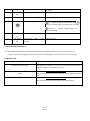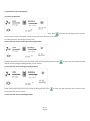
1
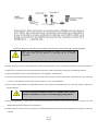
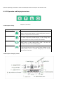
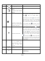
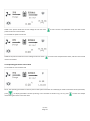
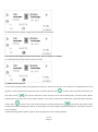
USER MANUAL
LCWS-B
Intelligent Buck & Boost Wind Solar Hybrid
20120314 VERSION 1
Safety Caution
1. Thank you for purchasing our controller. Before you install and use the product, please carefully read the User’s Manual and
properly keep it.
2. The controller shall be installed by an experienced technician in strict accordance with the User’s Manual, to guarantee that it
can work normally.
3. Keep the product free of contact with corrosive gas and humid environment for a long time.
4. Be sure not to place the product at a place where it is exposed to humidity, rain, sun, severe dust, vibration, corrosion, or strong
electromagnetic interference.
5. Please don’t open the product’s casing to repair it by yourself.
Table of Contents
I. Product Overview ............................................................................................................... 1
II. Description of Model.......................................................................................................... 2
III. Installation Specification ................................................................................................... 3
IV. LCD Operation and Display Instructions ............................................................................. 5
4.1 Descrption of keys .................................................................................................... 5
4.2 Description of display content ................................................................................... 5
4.3 Day and night identification ...................................................................................... 7
4.4 Output mode ............................................................................................................ 7
4.5 Instructions for control panel .................................................................................... 8
V. Protection Mechanism ..................................................................................................... 14
VI. Performance Parameters ................................................................................................ 14
VII. Common Faults and Troubleshooting ............................................................................. 16
VIII. Warranty and After-sale Service .................................................................................... 16
Ⅰ Product Overview
This controller is specially designed for high-end small wind-solar hybrid systems and applies to wind-solar hybrid street lighting
systems and wind-solar hybrid monitoring systems. Its main functions are shown as below:
1) This controller, being a high-performance wind-solar hybrid controller, can control wind generators and solar cells to charge or
discharge the storage batteries at the same time; when charging, it adopts high-resolution PWM mode to charge the storage
batteries via voltage and current limiting, which can effectively prolong the storage batteries’ service life;
2) The controller is provided with an accurate rotating speed measuring and controlling module, so it can check the wind generator
rotating speed in real time, and also can realize over-speed brake according to the set upper limit of safe rotating speed.
3) The controller is provided with two-channel DC output interfaces, and each channel has a maximum output current 10A; for
each channel, the user can independently set three kinds of different output modes, namely, light-controlled on/off,
light-controlled on/time-controlled off, and normally open.
4) The controller is provided with MPPT (maximum power point tracking) function. It, via advanced algorithm, can automatically
search the maximum power point to realize the maximum conversion from wind energy to electrical energy. Through test,
compared with traditional controllers, this controller can improve the charging efficiency by more than two times at maximum.
5) The controller is provided with a customized LCD, so the user can easily check and set the status of controller via the
human-computer interaction interface:
The items which can be checked: storage battery voltage, wind generator rotating speed, wind generator voltage, wind generator
current, wind generator power, photocell voltage, photocell current, photocell power, the first channel output mode, the first
channel output turn-off time, the second channel output mode, the second channel output turn-off time, light-controlled on
voltage point, light-controlled off voltage point, daytime or nighttime indicator, storage battery status, load status, as well as the
status of faults like over-voltage, under-voltage, over-load, and short-circuit.
The items which can be set: the first channel output mode, the first channel output turn-off time, the second channel output mode,
the second channel output turn-off time, light-controlled on voltage point, and light-controlled off voltage point.
6) The controller is provided with a unique solar charging circuit, with a small loss and heat, which is of open-circuit unloading
mode, so as to effectively prolong the solar cell’s service life.
第1页
Page 1
7) Complete safety protection functions, including:
solar cell reverse charging prevention protection
solar cell reverse connection prevention protection
solar cell current-limiting protection
storage battery over-charging, over-discharging protection
storage battery open-circuit protection
storage battery reverse connection prevention protection
overload, short-circuit protection
lightning protection
wind generator current-limiting protection
wind generator over-speed protection
automatic and manual brake protection of wind generator
controller temperature monitoring, over-heat protection
load over-voltage protection
※ Note: Except for storage battery reverse connection prevention protection, other protections above won’t damage the
components.
8) The controller casing made of high-quality aluminum alloy is well designed, and has an attractive appearance and a good heat
dissipation performance.
9) The controller is manufactured with strict production process and high-quality industrial components, so it can run reliably for a
long time under cold, high-temperature, or humid environment.
第2页
Page 2
Ⅱ Description of Model
LCW S-B1,B2
Internal code
Solar energy
Wind energy
※ Note: Refer to VI Performance Parameters for detailed information
Ⅲ
Installation Specification
Output terminal connection diagram of LCWS-Bx wind-solar hybrid controller with double-channel standard configuration
Output terminal connection diagram of LCWS-Bx wind-solar hybrid controller with single-channel dimming signal (optional)
第3页
Page 3
Connection diagram of LCWS-B wind-solar hybrid controller with communication port RS 485 (optional)
Dimmer port and communication port RS485 are optional, so the customer shall
clearly specify what you need; otherwise we will deliver the one in standard
configuration.
After the parts of wind-solar hybrid generator system and photovoltaic panel are installed and external circuit construction is
completed, it is required to connect and operate the system parts safely and reliably according to the following sequence.
1) Open the package to confirm that the equipment is not damaged in transportation.
2) Connect the DC load to DC OUTPUT terminal. The loads of two channels share the same anode. Connect the first-channel load to
“+”and“-1” of DC OUTPUT, and the second-channel load to “+”and“-2”of DC OUTPUT.
3) Connect the storage battery to the BATTERY terminal of back panel of equipment with the cable with copper conductor of
6mm2 and above.
A reverse connection between anode and cathode of the storage
batteries is forbidden, in order to avoid damaging components.
4) When wind generator is under static or low-speed running status (no wind), connect the wind generator output line to the
WIND INPUT terminal of back panel of equipment.
5) Shield and then connect the solar cell panel to the SOLAR INPUT terminal of back panel of equipment according to anode and
cathode.
第4页
Page 4
6) Set corresponding parameters to select the load output mode via the keys on the controller’s LCD.
IV. LCD Operation and Display Instructions
Diagram of panel keys
4.1 Description of keys
Symbol
Function description
Add or display the next value: if under browsing status, press it to
switch to next parameter display; if under setting status, press it to
add the current parameter value modified.
Reduce or display the previous value: if under browsing status, press
it to switch to previous parameter display; if under setting status,
press it to reduce the current parameter value modified.
Setting/confirmation: if under browsing status, press it to enter the
setting status; if under setting status, press it to store the
parameters and return to the browsing status.
Cancellation/manual switch: if under setting status, press it to return
to the browsing status but not to store the values modified; if under
browsing status, use it as a manual setting key in case of load
short-circuit or over-load.
4.2 Description of display content
第5页
Page 5
Serial No.
Symbol
Notes
Description
A
Indicating wind generator
B
A symbol of sun, indicating
daytime
A symbol of moon, indicating
nighttime
C
When the battery is fully charged, 5 bars inside will all
display
;
when
the
over-discharged, the symbol
storage
battery
is
will flicker and then
stop flickering upon recovery from over-discharging
status; when battery storage is under over-voltage
status, a battery status indicator bar will appear, and
A symbol of storage battery,
with the bars inside indicating
the over-voltage symbol
will flicker and then
stop flickering upon recovery from over-voltage status.
the battery charge status
Under a normal load, indicator lamp
will appear
when without output, while indicator lamp
will
appear when with output; under over-load status,
load symbol
flicker, at this time, you need to
eliminate the excessive load, and then press Esc key to
D
Load status and fault status
recover the output; under short-circuit protection
, short-circuit symbol
will be on, at this time,
you should check the load line and then press Esc key
after confirmation for normality to manually recover it
to original status.
E
(See
Figure
4.2)
An icon of manual brake: when
it is on, it indicates “under
manual brake status”, otherwise
“status
of
manual
brake
unlocked”.
F
G
(See Figure
An icon of the item browsed
4.2)
currently
(See Figure
Unit icons
4.2)
A: current, unit: A;
V: voltage, unit: V;
W: power, unit: W;
H: hour;
第6页
Page 6
M: minute.
H
(See Figure
Digital display zone
4.2)
I
SET
Indicating “under setting status”
A symbol of light & time control
is a symbol of light & time control. When
appears, it indicates light-controlled on/off; and when
appears, it indicates light-controlled on /
J
time-controlled off.
K
(See Figure
Output on/off status
4.2)
L
(See Figure
4.2)
Two–channel
load
output
Channels 1 and 2
interface
4.3 Day and night identification
It is night if the photocell voltage exceeds the light-controlled on voltage (can be set by users) for continuous 1min.
It is day if the photocell voltage exceeds the light-controlled off voltage (can be set by users) for continuous 1min.
4.4 Output mode
Output mode
Normally open output mode
Specification
The voltage of battery is normal and within the rated load. The
controller outputs will full power normally.
Light-controlled on/time-controlled off output
After dark (see 4.3 Day and night identification), it outputs according to
mode
the set load upper limit and the output off time is subject to the set
time.
Light-controlled on/off output mode
After dark (see 4.3 Day and night identification), it outputs according to
the set load upper limit and the output is off after the dawn).
第7页
Page 7
4.5 Instructions for control panel
4.5.1 Start-up interface
In the start-up interface, 0.00V shows the current voltage of storage battery. Press
key to enter into wind generator parameter
state, and the current rotate speed, voltage, current and power of wind can be viewed:
4.5.2 Wind generator operating parameter state:
4.5.2.1 View the current rotate speed of wind generator
0.00M in the picture shows the current actual rotate speed of wind generator. Press
to enter into next parameter state,
and the current voltage of wind generator can be viewed.
4.5.2.2 View the current voltage of wind generator
0.00V in the picture shows the current voltage of wind generator. Press
of wind generator can be viewed.
4.5.2.3 View the current of wind generator
第8页
Page 8
to enter into next parameter state, and the current
0.00A in the picture shows the current of wind generator. Press
to enter into next parameter state, and the current power of
wind generator can be viewed.
4.5.2.4 View the power of wind generator
0.00W in the picture shows the current power of wind generator. Press
solar PV parameter state, and the current voltage,
current and power of solar PV can be viewed.
4.5.3 Operating parameter state of solar PV module
4.5.3.1 View the voltage of solar PV
0.00V in the picture shows the current voltage of solar PV. Press
solar PV can be viewed.
4.5.3.2 View the current of solar PV
第9页
Page 9
to enter into the next parameter state, and the current of
0.00A in the picture shows the current voltage of solar PV. Press
to enter into the next parameter state, and the current
power of solar PV can be viewed.
4.5.3.3 View the power of solar PV
0.00W in the picture shows the current voltage of solar PV. Press
to enter into D load parameter status, and the current of DC
load can be viewed.
4.5.4 Operating parameter state of load
4.5.4.1 View the current of DC load
So far, the operating parameters of various parts of the system have been all viewed (if you need to look back certain parameter,
press
to display parameters counter-cyclically); In this interface as shown in Fig. 4.5.4.1, press
mode setting of Channel 1 and 2 DC load.
第 10 页
Page 10
to enter into output
4.5.5 DC load output mode setting interface
In this Manual, Channel 1 load is used as an example and its setting process is stated.
4.5.5.1 Normally open mode interface
In this interface as shown in Fig. 4.5.5.1, press
channel, press
and the Channel 1 or 2 load setting interface can be switched over. For each
"set/confirm" key first and the screen will display a “SET” sign, and then press
or
Channel 1
load can be switched over among the three output modes: normally open, light-controlled on/off, light-controlled
on/time-controlled off. Users only need to select the mode they need, and then press
key to save and quit.
4.5.5.2 Output mode interface of light-controlled on/off
第 11 页
Page 11
to confirm and press
ESC
4.5.5.3 Output mode interface of light-controlled on/time-controlled off
The output mode setting of Channel 2 is the same and its interface is as follows:
4.5.5.4 Output mode setting interface of Channel 2 load
4.5.6 Manual brake operation
To ensure the operation safety of wind generator and for the convenience of users, this controller is so designed that the wind
generator can be braked manually under any state. The specific process: keep
then press ESC key
“confirm” key on the panel pressed first, and
and hold for about 5min. Loosen the key to enter manual braking state, and there will be “Brake”
displayed at the top right corner of the display interface. If you want to quit manual braking state, repeat the above operation,
namely, keep
“confirm” key on the panel pressed first, and then press ESC key
and hold for about 5min. Loosen
the key to quit manual braking state. “Brake” at the top right corner of the display interface will disappear. The specific interface is
shown as follows:
1) Manual braking interface (“Brake” appears at the top right corner of the display interface)
第 12 页
Page 12
"Brake” appears, and the wind generator brakes
2) Quit manual braking (“Brake” at the top right corner of the display interface):
After wind generator brakes, it will stop rotating or rotate at a very slow
speed. The wind generator is unable to generate electricity.
"Brake” disappears, and the wind generator quits braking state.
第 13 页
Page 13
V. Protection Mechanism
1
Serial
Protection
No.
contents
General
over-speed brake
or brake off
2
Protection description
Remarks
If the rotate speed of wind generator exceeds the preset rotate
speed of braking, it will automatically brakes through three-phase
short circuit and the brake is off automatically after 3min.
The controller
has automatic
braking
function
Over-speed brake
If there are more than successive 3 overspeed brakes within 30min,
or brake off under
it will be determined as continuous strong wind and the brake can
continuous strong
be off automatically only after 4h.
wind
3
Exceeding
safe
temperature
When it exceeds the safe temperature because of overhigh ambient
The controller
temperature or overhigh temperature caused by heavy current, the
has a built-in
system will enable over-temperate protection automatically, disable
temperature
wind generator and photocell input, but the output will not be
testing module
affected.
4
Temperature
Over-temperature protection is freed, and the system recovers to
decreases to safe
normal state.
temperature
This controller has good heat dissipation measures and the over-temperature protection module will not be enabled
under non-extreme cases.
第 14 页
Page 14
VI Performance Parameters
Model
Sys tem vol tage
LCWS-B
12V
24V
Turbi ne i nput vol tage ra nge
0 ~ 100V
0 ~ 25A(15A)
Turbi ne i nput current ra nge (i ni tia l va l ue)
Turbi ne ma xi mum i nput power
PV Input vol tage ra nge
PV Input current ra nge (i ni tia l va l ue)
PV Ma xi mum i nput power
PV MPP
Number of output ci rcui ts
Output control mode
600W
1000W
0 ~ 25V
0 ~ 50V
0 ~ 100V
0 ~ 30A(15A)
0 ~ 30A(10A)
0 ~ 22A(8A)
500W
1000W
1500W
17 ~ 20V
34 ~ 40V
68 ~ 80V
2-cha nnel or 1-cha nnel wi th di mmi ng s i gna l
Al wa ys open;l i ght-control l ed; l i ght on/time off
10A
a bout0.4W
a bout0.8W
util i ty power i nterfa ce
Optiona l
Communi ca tion i nterfa ce
RS232 / RS485(optiona l )
-20 ~ +50℃
Opera ting tempera ture ra nge
Opera ting humi di ty ra nge
0 ~ 20A(15A)
350W
Ma xi mum output current
Static power
48V
35% ~ 85% (no condens a tion)
Product s i ze
190.5*150*85.5mm
Pa cka ge s i ze
233*182*130mm
wei ght
2.2Kg
第 15 页
Page 15
a bout1.0W
VII. Common Faults and Troubleshooting
If the above statements are not satisfied, or there is any abnormal phenomenon and the controller cannot return to normal,
please contact the after-sale service or business personnel of our company for maintenance or replacement in a timely manner.
Phenomenon
Storage battery box
Specification
flickers
and there is no output
It is over discharged. The storage battery is emptied. Please fully charge the
storage battery before use.
The system detected output overlead and will disable the overloaded output
Load icon
flickers and
there is no output
loop (the other loop will not be affected). Please check the loads, and remove
the unnecessary or abnormal loads. Press Esc to recover.
The system detected output short circuit and will disable the short circuited
is on and there is no output
output loop (the other loop will not be affected). Please check the loads and
connection lines. After troubleshooting, press Esc to recover.
The temperature of the controller is too high and the over-temperature
The output is normal but it is not
protection (the wind generator brakes, the photocell has open circuit, but the
charged.
output will not be affected). When the temperature decreases to recovery
temperature, the system will recover.
VIII. Warranty and After-sale Service
1. The product quality warranty of our company is one year, or in case of any defect or fault found within the quality warranty year
as agreed in the contract, our company will provide free maintenance service. Place contact the after-sale department or related
business personnel of our company.
2. The warranty range in this quality warranty clause is exclusive of damages caused by external factors, such as damages caused
by force majeure, e.g. accident and natural calamities, use not in accordance with the product specification, improper use,
negligence, refit, repair, improper installation, improper testing, improper transportation, etc.
第 16 页
Page 16