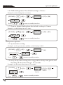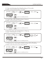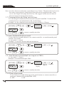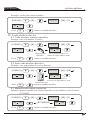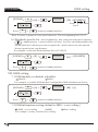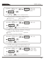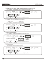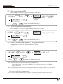
1
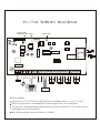
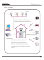
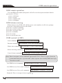
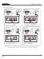
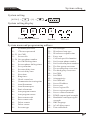
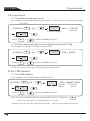
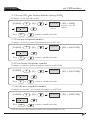
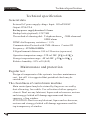
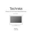
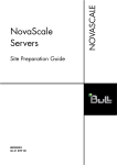
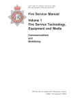
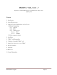
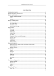
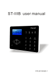
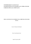
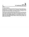
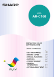
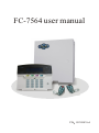
FC-7564 user manual
DISARM
ALARM
FAULT
POWER
COM
ARM
P/N 20120815-A
FC-7564 WIRING DIAGRAM
LED display
on Metal case GSM
Tel.line
Telephone
LED Flash
AC
AC
+BELL-
KEY+ GND
TX
RX
+12V GND
A
B
Yellow
Power
Z2
Z3
GND
Z4
Z5
GND
Z6
Z7 GND
Z8
White
Aux power
output
13VAC 2A
Z1 GND
2.2K 2.2K
2.2K 2.2K
2.2K 2.2K
2.2K 2.2K
Arm
Disarm
Fault
Delete
Frice
Panic
Medical
Confirm
Check
Arm
Disarm
BUS
Home
#
Bypass
Power supply
Only can use12V/7A sealed lead-acid battery,change battery every 3-5 years
With 1 keypad,power consumption 250mA,support for 16 working hrs.
Total power consumption(keypad,auxiliary power,siren)can~t exceed max.power
consumption of control panel
Max.Rechargeable current of battery:350MA
Content
Foreword
Features
Alarm procedure
1.Remote control by phone
2.Follow me operation
GSM remote operation
GSM alarm receiving
GSM control via SMS
Keypad
LED display on Metal case
C7601 BUS zone expander
Basic operation
System setting
I.Set password
1.1 Set administrator password
1.2 Set user password
II.set CMS number
2.1 Set CMS number
2.2 Set user Id
2.3 Free arm telephone number
2.4 Free disarm telephone number
2.5 Set the user telephone number
2.6 CMS dialing times
2.7 The user phone dialing time
III.System options
3.1 System time setting
3.2 Entry delay time setting
3.3 Set exit delay time
3.4 Siren time
3.5 Set ring time
3.6 Detector loss check
3.7 Communication checking interval time
3.8 Arm,disarm indication sound
3.9 Arm/disarm report
3.10 Panic alrm sound
IV. Code wireless device
4.1 Code wireless remote controller
4.2 Auto code wireless detector
4.3 Manual code remote controller
1
2
3
4
4
6
6
6
7
8
9
10
11
12
12
12
12
12
13
13
13
13
14
14
14
14
14
15
15
15
15
16
16
16
16
17
17
17
17
4.4 Manual code wireless detector
4.5 Delete remote controller
4.6 Delete detectors
V.System zone setting
5.1 Zone type setting
5.2 Zone siren type setting
5.3 Wired zone loop type
5.4 The response speed of wireless
VI.Other options setting
6.1 AC power fault report delay
6.2 Time calibration
6.3 Force arming
6.4 Cross protection areas
6.5 Dial back specific Number
VII.GSM setting
7.1 GSM module set
7.2 GSM information setting
7.3 Alarm priorities
7.4 GSM message language
7.5 DTMF output signal strength
7.6 Handshake voice input signal strength
7.7 GPRS setting
7.8 Server IP address
7.9 Server port
7.10 Server registered ID
7.11 Server registered passwordh
7.12 Server connection
Technical specification
Maintenance and protection
Limitation of the Products
18
18
18
18
19
19
19
20
20
20
21
21
21
22
22
22
22
23
23
23
24
24
24
24
25
25
25
26
26
27
Foreword
User manual
Foreword
FC-7564 is a intelligent alarm control system which in tegrated
with burglarproof, fireproof, gas leak proof. It is compatible with
wired and wireless alarm mode.
FC-7564 refers to the most advanced coding techniques of BUS
zone and multi-bit random code-hopping techniques in security &
reliability, to avoid false alarm and interf erence effectively.
1.64 zones:8 wired, 24 wireless and 32 BUS zone
2.6 way to arm and disarm the system: User code, Keyfob, Phone,
SMS, Auto timer, CMS
3.Alarm notification: When alarm occurs, user can have alarm
notification by phone call, SMS, GPRS, TCP/IP(optional)
Smart feature of FC-7564
1. Multi-zones combination alarm, special design for the places
suchas watchroom, bedromm and etc.
2.Can use without keypad
3.LED display on metal case, easier for user to check system info.
Warning!!!
Don t disassemble or modify, or else may be lead to danger and
the damage of panel.
Be sure not to cause to break by falling or throwing down or
strong impacting. Not install near the magnetic field, may
because instability.
Keep dry and clean. Don t install the panel in the site which has
oily fume, water-vapour, much poudre.
Be keep out of the sun and heat. Don t install the panel near the
heating stove etc. high temperature equipment, such as spotlight.
Keep out of the direct sunlight, may cause color fading.
When cleaning, wipe with the mull. To remove dirt need to use
detergent, don t use gasoline or paint thinner etc. chemicals. Or
else may cause damage or the paint scaled off the panel.
User manual
Features:
Zones: 8 wired/24wireless/32BUS zone
Keypad and remote: Support 8 pcs LCD keypad and 8remotes
Password: 1 installer code, 1 duress code, 15 user codes
CMS: 2 CMS follow me numbers, 1 account number
Voice number: 4 voice numbers, Voice prompting operation
Event log: 128 event logs
Module expanded: GSM/GPRS module
Recording:10-second automatic message Recording
Features
Alarm procedure
User manual
Alarm procedure
Tele
telephone
Telephone
1st
2nd
Cell phone
3rd
4th
3.The panel will dial 1-4 telephone numbers
as preset.If more than 4 numbers,the panel will
W
ire
d
start with second telephone number, then 3,4...
BUS
Alarm software
Alarm situation found,
start to send message
DISARM
ALARM
FAULT
POWER
COM
ARM
1.The detector activated send
alarm information to alarming center
CMS
110 alarm center
2.The panel use Ademco Contact ID to send
wi
alarm information to alarming center.
If the panel got confirmation from center,
then alarm successfully.Otherwise, the panel
will repeat alarm.The alarm information will
be display and reslove by the alarm center computer
software.
rel
es
s
Remote control by phone
User manual
1 Remote control by phone
1
2
When user answer the call,the panel
pick up phone after preset rinings
User to call landlines phone
which connect to the panel
3
"Welcome to your security
system Enter your user code"
4
1 2 3 4
Enter the user code as per voice
prompting(factory default
code: 1234)
System disarm, press one
System arm, press two
System home arm, press three
Play the zone address recording, press nine
Hang up, press zero
5
2 Follow me operation
When the detector is triggered, the panel will sound alarm and display the triggered
zone number and alarm type on the LCD screen. The panel will give a alarm and dial
the preset voice numbers if the panel received the alarm.
The user can hear indication after he took th e phone.The user operate follow the
voice indication to disarm/arm
inquire and mornitor .
1
DISARM
ALARM
FAULT
POWER
COM
2
ARM
Send the alarm signal
Panel receivealarm,
and dial voice number
Follow me operation
User manual
3
User answer the call
Cancel the alarm press one
Check alarm zone press two
Activate the hoot press three
To disable the siren press four
Disarm system press five
Arm the system press six
Stay arm the system press seven
Play the zone address recording press nine
Hand up press zero
4
GSM remote operation
User manual
GSM remote operation
You can SIM card number,then panel will off revised user password,the default
password is 1234,as
press 1 to disarm
press 2 to arm
press 3 to home arm
press 0 to hangup
GSM alarm receiving
When alarm occurs,GSM will call the preset voice number,it will voice prompt
system is alarm,please process the alarm
press one to cancel alarming
press two to check alarm zone
press three to trigger siren
press five to disarm
press six to arm
press seven to home arm
GSM control via SMS
Arm command
PASSWORD:1234 SYSTEM ARM
Disarm command
PASSWORD:1234 SYSTEM DISARM
Home arm command
PASSWORD:1234 SYSTEM HOME
Status checking command
PASSWORD:1234 SYSTEM STATUS
Cancel alarm command PASSWORD:1234 SYSTEM CANCEL
Note:There is no space in the command password:1234
,There is a space between
system and arm.enter system arm ,when operate successfully,SMS auto reply
Arm Successful .
Set GPRS access command
PASSWORD:1234 APN:
aaaaaa
Set GPRS access User name command
PASSWORD:1234 USER: bbbbbb
Set GPRS access User code command
PASSWORD:1234 PWD:
Remarks:There is no space between APN:
cccccc
Keypad
User manual
Keypad description
Power LED
Disarm LED
Power
Arm
Disarm
Fault
Frice
Panic
Delete
Confirm
Medical
Check
Arm LED
Fault LED
Arm
Disarm
Numeric keyboard
Speech indication
Home
#
Bypass
Power LED: it will normal ON when AC and battery without any trouble. It will off
when both AC and battery with trouble. It will slow flash when battery
with trouble, it will quick flash when AC with trouble.
Fault LED: It will slow flash when communication with trouble, it will off when
without any troubles.
Arm LED: It will ON when armed, slow flash when stay in, quick flash when alarm.
Disarm LED: It will ON when disarmed, it will OFF when zone trouble.
Fire : The panel will send out alarm
Check : Press CHECK key to check the
signal when press FIRE key 3 for
alarm events , it used as Confirme
seconds, it used as UP key when
key when programming.
programming.
: W hen y ou e ntering n umbers,
Panic : The panel will send out alarm
press , the LCD screen will
signal when press PANIC key for 3
display
P, means 2s pause
seconds, it used as DOWN key
when dialing, for other settings,
when programming.
press means EXIT.
Medical : The panel will send out alarm
:When enter errors, press # can
signal when press HELP key for 3
delete the errors, it used as
seconds, it used as DELETE key
Confirm key when programming.
when programming.
Basic operation
Factory default Admin password: 012345
Factory default User password: 1234
Arm: User password[1234]+ Arm
Home: User password[1234]+ Home
Disarm: User password[1234]+ Disarm
Bypass: User password[1234]+ Bypass + zone number +
#
LED display on Metal case
User manual
Enter system setting : Admin password[012345]+
+[0]+
#
Exit system setting:
#
Password reset: You can enter installer code 000000 to enter setup only during the
first 1 minute when the alarm is powered on.
*
*
LED display on Metal case
Disarm
Power
Alarm
Comm
Fault
Arm
POWER LED it will normal ON when AC and battery without any trouble. It will off
when both AC and battery with trouble. It will slow flash when battery
with trouble, it will quick flash when AC with trouble.
FAULT LED: It will ON when zone troubles.
ARM LED: It will ON when armed, slow flash when stay in.
DISARM LED: It will ON when disarmed
COMM LED: It will flash when communication trouble.
ALARM LED: It will flash when alarm.
Zone trouble indication
it means that 8 zone alarm
it means that 8 zone trouble
it means that 8 zone bypass
Note: if the LCD also display zone alarm when the user disarmed the system after
alarming, please disarm the system again, then LCD display will resume.
FC-7601 BUS zone expander
User manual
FC-7601 BUS zone expander
(Fig 1)
1.FC-7601 is single zone module via dip switch address, EOL 10k
2.Zone expanded :NO.1-128
3.Wire: red(DC+), Brown(DC-), Yellow(A), White(B), Green( zone inspection)
Brown also GND.
4.Working voltage: DC8.5-24V
5.DIP 1 tamper inspection switch, ON to enable tamper, OFF-to disable tamper
2-8 address digit. OFF enable, ON-disable. Binary address, To set zone 18, user
should be put DIP 4 and DIP 8 to be OFF,See (fig 1) allmodule address should be plus one.
6.The zone number in BUS module=module address number + 32 , Eg. Zone 50=module
address 18+40
7.Zone 33-64 is disable by factory default, user should enable firstly before use.
WHITE
YELLOW
GREEN
NO TAMPER
BROWN
RED
WHITE
YELLOW
GREEN
BROWN
RED
FC-7601
SINGLE ZONE
FC-7601
SINGLE ZONE
TAMPER
Basic operation
User manual
Basic operation
Disarm
Arm
Power
Arm
Disarm
¡«àÖ¡«
Fault
Delete
Frice
Panic
Medical
#
Power
Arm
Disarm
Delete
Check
Frice
Panic
Arm
Disarm
Home
Home
Bypass
#
M
Arm
or the away
Emergency
Power
Disarm
Delete
Confirm
Medical
Check
D
User code [1234] +
Arm
Power
Disarm
Arm
Fault
Frice
Panic
Delete
Confirm
Medical
Check
Arm
Arm
Disarm
Home
Home
Bypass
#
Y
Emergency help:press key in the keyfob
or press Panic and hold for 3s
or the
Stay arm
Fault
D
Disarm
DISARM button on the keyfob
Disarm
#
M
Bypass
Y
D
ARM button in the keyfob
Panic
Check
Arm
User code[1234] +
Frice
Medical
Confirm
Disarm
Y
M
¡«àÖ¡«
Fault
Confirm
Bypass
Y
M
D
User code + Stay or press the home
ARM key in the keyfob.
Note: If the LCD also display zone alarm when the user disarmed the system after
alarming, please disarm the system again, then LCD display will resume.
System setting
User manual
System setting
[012345] +
*
+ [0] +
#
System setting display
2
0
Programming address
6
0
Set data
5
Data bit
System menu and programming address
01-02-20--21
22-23--26
27-28-30-31-32-33-34-35-36-37-38-39-40-41-42-43-44-45-50--
Set admin password
17Set user password
Set CMS
Set user No.
Set user phone number
Set CMS dialing times
Set user phone dialing times
Set system time
Set enter delay time
Set exit delay time
Siren time
Ring times
Check sensor loss
Communication testing time
Arm/disarm tone
Arm/disarm report
Panic alarm tone
Auto program remote
Auto program sensor
Enter remote code
Enter sensor code
Delete remote
Delete sensor
Set zone type
51-52-53-60-61-62-63-70-71-72-80-81-82-83-84-85-86-87-88-89-90-91-98-99--
Set siren type
Wired zone loop type
Wired zone response time
Force arm
Call back specified number
Set free arm phone number
Set free disarm phone number
The first group cross zone
The second group cross zone
The third group cross zone
Set GSM
Set GPRS
Alarm priority
Set GSM info
Server IP address
Server port
Server register ID
Server register password
Server connection mode
DTMF output signal strength
Handshake tone input signal
strength
SMS language
AC off delay report
Time calibration
Set password
User manual
I.Set password
1.1 Set administrator password
For example: set the administrator password as 112233, the factory default password
is 012345.
[012345] +
01
*
3
+ [01] + [112233]
LCD screen display
Password
#
+
06
----
#
+ [0] +
LCD screen display
Press
*
#
+
return to standby interface
1.2 Set user password the factory default password:1234
For example:set the NO.3 user password as 5678
[012345] +
04
*
8
04
*
Press
+ [04] + [5678]
#
+
#
+
----
#
+ [0] +
return to standby interface
NOTE:User can set 16 user passwords,the program address:02-17
II.Set CMS number
2.1 Set CMS number
For example:set the CMS number as 9P80012345
[012345] +
20
Press
*
+ [0] +
*
+
----
#
+
11
#
#
+ [20] + [9 80012345]
Program
address
*
Telephone
number
return to standby interface
Note: user can set 2 CMS numbers,the program address:20-21 when press
LCD screen dispaly asP it means dial pause 2 seconds.
The dial pause only for connecting with extensions
*
otherwise,press 80012345 directly.
set CMS number
User manual
2.2 Set user ID the factory default setting :0000
Example: set the user ID as 6666
[012345] +
22
*
+ [0] +
---LCD screen
display
#
+
05
#
+ [22] + [6666]
Program User ID
address
LCD screen dispaly
Press
*
#
+
return to standby interface
2.3 Free arm telephone number
Example: set the free arm telephone number as 84113252
[012345] +
62
Press
*
#
+
#
----
+ [62] + [84113252]
#
+
09
*
+ [0] +
return to standby interface
2.4 Free disarm telephone number
Example: set the free disarm telephone number as 84113268
[012345] +
63
Press
*
#
+
#
----
+ [63] + [84113268]
#
+
09
*
+ [0] +
return to standby interface
2.5 Set the user telephone number
Example: set the NO.3 user telephone number as 93872105
[012345] +
25
Press
*
+
#
----
+ [25] + [93872105]
#
+
09
*
+ [0] +
#
return to standby interface
Note:user can set 4 user telephone numbers,the program address:23-26
system options
User manual
2.6 CMS dialing times.The default setting is 5 times
Example:set the dialing time as 4 times.
[012345] +
27
4
Press
*
*
+ [27] + [04]
#
+
02
----
#
+ [0] +
#
+
return to standby interface
2.7 The user phone dialing time:the default setting is 5 times
Example: set the dialing time as 3 times
[012345] +
28
Press
3
*
*
+
+ [28] + [03]
#
+
02
----
#
+ [0] +
#
return to standby interface
III.System options
3.1 System time setting
Example: set the system time and date as 10:01,July,11,2012
[012345] +
*
+ [1207111001]
Y
M
D
H
30
----
#
+ [0] +
1
10
M
+
+ [30]
#
Year Month Day Hour Minute
Press
*
+
#
return to standby interface
3.2 Entry delay time setting:after triggerd the delay zone,panel start
alarming.the default setting is 10 seconds.
Example: set the entry delay time as 15 seconds.
[012345] +
31
5
03
*
+
+ [0] +
#
#
---LCD screen
dispaly
LCD screen dispaly
Press
*
+
#
return to standby interface
+ [31] + [015]
Program
address
Time
system options
User manual
3.3 Set exit delay time:the default setting is 10seconds.
Example: set the exit delay time as 15 seconds.
[012345] +
32
Press
5
03
*
*
+ [0] +
+
#
+
#
#
----
+ [32] + [015]
return to standby interface
3.4 Siren time the default setting is 5mins
Example: set the siren time as 10 mins
[012345] +
33
Press
0
02
*
*
+ [0] +
+
#
+
#
#
----
+ [33] + [10]
return to standby interface
3.5 Set ring time the default time is 7times
Example: set the ring time as 5 times.
[012345] +
34
5
02
*
+
+ [0] +
#
---LCD screen
dispaly
#
+ [34] + [05]
Program Time
address
LCD screen dispaly
Press
*
+
#
return to standby interface
3.6 Detector loss check the default setting is00 as Disable
Example:set the detector loss check time as 4hours
[012345] +
35
Press
4
02
*
*
+ [0] +
+
#
+
#
#
----
return to standby interface
+ [35] + [04]
system options
User manual
Note: wireless detector send status report about every 3 hours. The panel check if receiver
the status report signal or alarm signal from detector at programed time. If not
receive the singal, will judge detector loss. We suggest set the neterval time of
detector inspection longer than 4 hours.
3.7 Communication checking interval time :
It is checking of communication between alarm panel and CMS. To check if the
communication is normal(default is 00, not checking)
Example: set the communication checking interval time as 15 hours.
[012345] +
36
Press
5
03
*
*
+ [0] +
+
#
+
#
#
----
+ [36] + [015]
return to standby interface
3.8 Arm, disarm indication sound:
To set if the siren sound when user use remote controller to arm,disarm the panel
(default: not sound)
0> not sound 1>sound
Example: set the arm /disarm indication sound on
[012345] +
37
Press
1
01
*
*
+
+
+ [0] +
#
----
+ [37] + [1]
#
#
return to standby interface
3.9 Arm/disarm report(default: not report to CMS)
0> not report 1> report
Example: set arm/disarm report CMS
[012345] +
38
1
01
*
+
+ [0] +
#
#
---LCD screen
dispaly
+ [38] + [1]
Program 1>Report
address
LCD screen dispaly
Press
*
+
#
return to standby interface
3.10 Panic alrm sound:
To set if the siren sound when trigger the panic button on remote controller or
emergency button on keypad(default: OFF)
0> OFF
1> ON
system options
User manual
Example: set the panic alarm sound on
[012345] +
39
Press
1
01
*
*
+ [0] +
+
#
+
#
#
----
+ [39] + [1]
return to standby interface
IV. Code wireless device
4.1 Code wireless remote controller
Example: auto code number 5 remote
[012345] +
40
5
01
*
+
+ [0] +
#
----
#
40
1
+ [40] + [5]
+
01
#
1 01 is the first number of
Trigger remote
remote is 9 digit address code
controller
Press
*
+
#
return to standby interface
4.2 Auto code wireless detector
Example: auto code number 9 wireless detector
[012345] +
41
9
02
*
+
+ [0] +
#
----
#
41
2
+ [41] + [09]
+
01
#
2 01 is the first number of
wireless is 9 digit address code
Trigger
wirelers detector
Press
*
+
#
return to standby interface
4.3 Manual code remote controller
Example: manual code the first remote controller by enter address code of remote
077230023
[012345] +
42
Press
1
01
*
*
+ [0] +
+
#
+
#
#
----
[077230023]
41
return to standby interface
+ [42] + [1]
3
09
+
#
system zone setting
User manual
4.4 Manual code wireless detector
Example: manual code the number 24 wireless detector by enter the address code
035126025
[012345] +
43
Press
4
02
*
*
#
+ [0] +
+
#
+
#
----
[035126025]
43
+ [43] + [24]
5
09
+
#
return to standby interface
4.5 Delete remote controller
Example: delete the number 8 remote controller
[012345] +
44
8
01
*
+
+ [0] +
#
---LCD screen
dispaly
#
+ [44] + [8]
Program Address
code
address
LCD screen dispaly
# return to standby interface
*
Note: enter 0 to delete all remote controller
+
Press
4.6 Delete detectors
Example: delete number 11 detector
[012345] +
45
1
02
*
+
+ [0] +
#
---LCD screen
dispaly
#
+ [45] + [11]
Program Address
code
address
LCD screen dispaly
Press
*
+
#
return to standby interface
Note: enter 00 to delete all detectors
V.System zone setting
5.1 Zone type setting
Options of zone type as below
0>disable
1>delay
3>burglar
4>24 hours
6> fire alarm
2>perimeter
5> emergency
For example: set protection area 7 and 8 as one group of the double direction one-shot
mode cross protection area. Preset time is 50 seconds.
system zone setting
User manual
Burglar alarm zone only trigger under system arm status, delay and perimeter zone
trigger under stay or arm status.
24 hours, emergency and fire alarm zone will trigger under any system status
Factory default:
Wired zone 1-8 enable, wireless zone 9-32 enable, bus zone 33-64 disable, 00 is system
zone. Pls connect resistor 2.2k to wired zone before power on the alarm panel, otherwiset
he alarm panel will make alarm or cause zone trouble. When need use bus zone, 7601 one
zone expand module is required.
Example: set the number 59 zone as fire alarm zone
[012345] +
50
+ [6]
Type
Press
*
+ [0] +
6
03
+
----
#
#
LCD screen
dispaly
+ [50] + [59]
Program Zone
address
LCD screen dispaly
*
+
#
return to standby interface
Note: If only check the zone type, then enter zone number, then press
#
button.
The LCD will display the zone type.
5.2 Zone siren type setting(default continious sound)
The options of siren type:
0>mute 1> continious sound 1> pulse tone
Example
set zone 33 siren type as pulse tone
[012345] +
51
+ [2]
Type
Press
*
+ [0] +
2
03
+
#
#
---LCD screen
dispaly
+ [51] + [33]
Program Zone
address
LCD screen dispaly
*
+
#
return to standby interface
Note: if only check the zone siren type, enter zone
the LCD will display the siren type
#
, then press
5.3 Wired zone loop type(default: resistor loop)
The options of wired zone loop type:
0>N.O loop, zone open loop normal, short-cut loop alarm
1>N.C loop, zone short-cut loop normal, open loop alarm
#
button,
Other options setting
User manual
Eol resistor N.G wiring
Eol resistor N.O wiring
For example: set the protection area No.6 as N.C loop
[012345] +
*
52
+ [2]
*
Press
+
+ [0] +
2
02
#
+
#
----
+ [52] + [6]
#
return to standby interface
Note: if only see the loop type in the wired protection area, press
loop type after inputting the protection area number
#
to display the
5.4 The response speed of wireless protection area (default is 500ms)
Configurable response speed of wireless protection area as below
For example: set the response speed for protection area No.3 is 10ms, Screen shows
[012345] +
*
53
+ [1]
1>10ms
1
02
+
#
#
---LCD screen
dispaly
+ [53] + [3]
Program Zone
address
LCD screen dispaly
*
Press
+ [0] +
+
#
return to standby interface
Note: If only can see the response speed of wireless areas, after inputting the protection
areas No. and press # , it will display the response speed. The common detector
s response speed is 500ms, 10ms for High speed detectors and vibration sensors.
. VI.Other
options setting
6.1 AC power fault report delay: when there is AC power fault occurs, the
delay time for reporting to the alarm receiving centre default for 30 minutes.
For example: set the delay time of AC power fault report is 5 minutes
[012345] +
98
Press
*
5
*
+ [0] +
02
+
+
#
#
----
#
return to standby interface
+ [98] + [05]
Other options setting
User manual
Note: if the delayed time setting is 0 minutes, it means that it will not report the power
fault information.
6.2 Time calibration
For example: If the panel time every 24 hours fast 20 seconds, take the formula
20x100/24=83 to calibrate, then set this value is 083. If slows 20 seconds, then
it is 183 to calibrate the time.
[012345] +
99
Press
*
3
*
+ [0] +
03
+
+
#
#
----
+ [99] + [083]
#
return to standby interface
6.3 Force arming: Allow users to arm when protection area faults. In the state of
the arming, the protection areas and recovery information will report to alarm
receiving centre. Default is disable.
0>Disable force arming
1>Enable force arming
For example: set enable force arming
[012345] +
60
Press
*
*
+ [0] +
101
+
+
#
#
----
+ [60] + [1]
#
return to standby interface
6.4 Cross protection areas: protection area 1+protection area 2 + time + mode.
Configurable cross protection area mode as below
0>Cancel cross model
1> The double direction twice-trigger mode : single trigger protection area 1, 2,
it will not alarm, trigger first protection 1, then trigger protection area 2 within
preset time, it will alarm; first trigger protection area 2 then area 1, it will not alarm.
2>The double direction One-Shot mode: trigger protection area 1, protection area 1
alarm; trigger protection area 2 first then protection area 1 within preset time, then
it will not alarm; trigger protection area 1 behind the preset time, the protection
area 2 will alarm.
3>Twice-trigger alarm mode: one-shot trigger protection are 1 or 2, it will not alarm,
trigger protection area 1 and 2 in preset time separately, then protection area 1 and
2 alarm.
GSM setting
User manual
[012345] +
70
Press
*
208
*
+
+ [0] +
+
#
#
----
+ [70] + [07080502]
Zone 1
Time Mode
Zone 2
#
return to standby interface
Note: It can set 3 groups of cross protection areas. The corresponding No is 70-72
6.5 Dial back specific No. : dial telephone No. that connected with panel, input the
#
+ administrator s password after off-hook. It will be on-hook automatically
and the panel will call the preset the telephone No. which can execute the arm and
disarm operation in a long distance.
For example: set the dial back telephone No. is 12345678.
[012345] +
61
Press
*
*
+ [0] +
+
09
+
#
#
----
+ [61] + [12345678]
#
return to standby interface
VII.GSM setting
7.1 GSM module set (default is disable)
Disable
Enable
For example: set enable GSM module.Configurable GSM information as below.
[012345] +
80
*
101
+ [0] +
+
#
----
+ [80] + [1]
#
LCD screen dispaly
Press
*
+
#
return to standby interface
7.2 GSM information setting (default is SMS + voice calling)
SMS + voice calling
SMS
For example: set only can dial voice calling.
Voice calling
GSM setting
User manual
[012345] +
83
*
201
+ [0] +
#
LCD screen
dispaly
#
+
----
+ [83] + [2]
Program Type
address
LCD screen dispaly
Press
*
#
+
return to standby interface
7.3 Alarm priorities (default is GSM priority)
GSM priority
PSTN priority
For example: set telephone line is priority
[012345] +
82
Press
*
*
101
+ [0] +
+
#
+
#
----
+ [82] + [1]
#
return to standby interface
7.4 GSM message language (default is Chinese)
Configurable SMS language as below
Chinese
English
For example: set message as English
[012345] +
91
Press
*
*
101
+
+ [0] +
+
#
#
----
+ [91] + [1]
#
return to standby interface
7.5. DTMF output signal strength(default is 04)
For example: set DTMF output signal strength is 05
[012345] +
89
*
502
+ [0] +
+
#
#
---LCD screen
dispaly
LCD screen dispaly
Press
*
+
#
return to standby interface
+ [89] + [05]
Program Signal
address stregth
GSM setting
User manual
7.6 Hand skake voice input signal strength (default is 60)
For example: set handshake voice input signal strength is 70
[012345] +
*
90
Press
002
*
+
----
#
+ [0] +
+ [90] + [70]
#
+
#
return to standby interface
7.7 GPRS setting (default is disable)
Disable
Enable
For example: set enable GPRS function.
[012345] +
81
Press
*
101
*
+ [81] + [1]
#
+
#
+
----
#
+ [0] +
return to standby interface
7.8 Server IP address
For example: set Server IP address is 202.101.78.2
[012345] +
*
+ [0] +
84
+ [202101078002]
Press
*
+
#
----
#
212
+
+ [84]
#
return to standby interface
7.9 Server port
For example: set Server port is 03467
[012345] +
85
Press
*
*
705
+
+ [0] +
+
#
#
----
#
return to standby interface
+ [85] + [03467]
GSM setting
User manual
7.10 Server registered ID
For example: set server registered ID is 75640001
[012345] +
86
*
108
#
+ [0] +
+
---LCD screen
dispaly
#
+ [86] + [75640001]
Program
address
User ID
LCD screen dispaly
Press
*
+
#
return to standby interface
7.11. Server registered password
For example: set Server registered password is 12345678
[012345] +
*
87
808
Press
*
#
+ [0] +
+
+
#
----
+ [87] + [12345678]
#
return to standby interface
7.12 Server connection (default is long connection)
Configurable comection method mode as below
Long connection
Short connection
For example: set connection is short one
[012345] +
88
Press
*
*
101
+
+ [0] +
+
#
#
----
+ [88] + [1]
#
return to standby interface
Note: Enable GPRS function need to enable GSM module.
Long connection: do not deal with SMS, voice calling and Server, via GPRS
long connection.
Short connection: when it have voice calling and SMS, the system will cut off connection
with GPRS, and deal with the voice calling and SMS priority. When this is done, GPRS
will connect with Server automatically.
Server registered ID and password: GPRS can registered must have the correct ID and
password that registered in the Server. it must be 8 digitals for the ID and passwords.
User manual
Technical specification
Technical specification
General data
External AC power supply vdtage: Input: 185 230VAC
Output:13VAC/2A
Backup power supply duration:16 hours
Backup battey(optiond): 12V/7AH
The method of alarming dial: Telephone alarm GSM alarm and
GPRS alarm
DTMF dial frequency variation :< 1.5%
Communication Protocol with CMS: Ademco Contact ID
Frequency: 433MHz/868MHz
E Signal transmit distance: 100 to 120 meters (open area)
Operation temperature range: 32F to 120F 0 to 45
Storage temperature range: -4F to140F -20 to 60
Relative humidity: 85% at 30 (86F)
Maintenance and protection
Regular test
Design of components of the system is to reduce maintenance
cost, but still it is suggested that periodical check may be
carried out.
The cleanliness of control main machine
Main control panel maybe be stained by fingers or covered by
dust after using for a while. Use soft cotton cloth or sponge to
clean it. Don't use any lubricant, liquor such as kerosene, acetone
and strong gel which will damage appearanceand the tran
sparency of top window.
ATTENTION: Don't use any lubricant, liquor such as kerosene,
acetone and strong gel which will damage appearance and the
top transparency of window.
Limitation of the Products
User manual
Limitation of the Products
Although the products is a high standard products, there is also
some limitation of them such as false alarm or no alarm, the
reasons may be below:
Lack of Maintenance. The system needs maintenance and test
regularly test. The sensitive of the detectors may decrease and
the siren may not whistle.
Lack of power supply If no power input and the back up power
is not enough, the panel can not work normally.
Telephone Line False If the telephone line is cut, the panel
could not send alarm signals
Limitation of Smoke Detectors if the smoke is far from the
smoke detector, the detector could not alarm
If the intruder break in through some door or window not
monitored, or some one knows hot to make the system not
work.