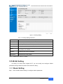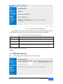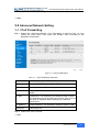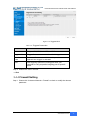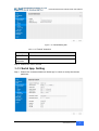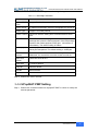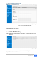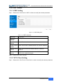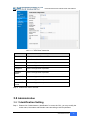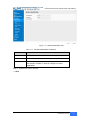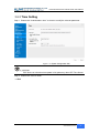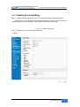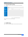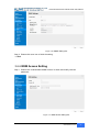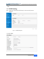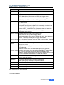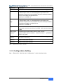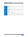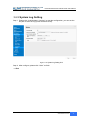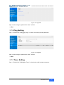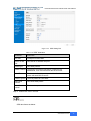
1
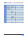
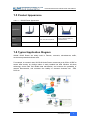
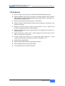
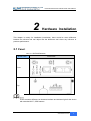
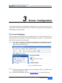
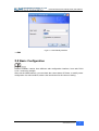
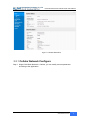
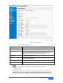
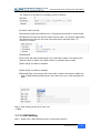
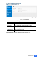
User Manual ---Apply to WL-R210 Series 3G/4G Router V3.1 http://www.wlink-tech.com 2015/03/31 Industrial R210 Series Cellular Router User Manual Copyright © Shenzhen WLINK Technology Company Limited 2012 ~ 2015 Without our written approval, Anyone can’t extract, copy whole or part of content of this file and can’t spread out in any format. Caution Due to product updates or functional upgrading, we may renew the content of this file, and this file only for reference. All statement, information, suggestion.etc in this file does not compose any form of guarantee and we WLINK reserves the right of final explanation. Shenzhen WLINK Technology Company Limited Add: 6F, Yiben Building, Chaguang Road, Xili, Nanshan District, China, 518054 Web: http://www.wlink-tech.com Service Email: [email protected] Tel: 86-755-26059261 Fax: 86-755-26059261 www.wlink-tech.com 1 Industrial R210 Series Cellular Router User Manual Contents Contents........................................................................................................................................... 2 1 Product Introduction.................................................................................................................... 4 1.1 Product overview ............................................................................................................. 4 1.2 Model introduction ........................................................................................................... 4 1.3 Product Appearance ........................................................................................................ 6 1.4 Typical Application Diagram ........................................................................................... 6 1.5 Features ............................................................................................................................ 7 2 Hardware Installation .................................................................................................................. 8 2.1 Panel:................................................................................................................................. 8 2.2 LED Status ........................................................................................................................ 9 2.3 How to Install .................................................................................................................. 10 3 Router Configuration ................................................................................................................ 12 3.1 Local Configure .............................................................................................................. 12 3.2 Basic Configuration ....................................................................................................... 13 3.3 WLAN Setting ................................................................................................................. 19 3.4 Advanced Network Setting ........................................................................................... 22 3.5 VPN Tunnel ..................................................................................................................... 28 3.6 Administration................................................................................................................. 29 3.7 Debugging Setting ......................................................................................................... 42 www.wlink-tech.com 2 Industrial R210 Series Cellular Router User Manual 3.8 “Reset” Button for Restore Factory Setting................................................................ 45 3.9 Appendix (For advanced optional features only) ...................................................... 45 www.wlink-tech.com 3 Industrial R210 Series Cellular Router User Manual 1 Product Introduction 1.1 Product overview WLINK industrial Router use industrial grade design, high-powered 32bit MIPS network processor, embedded industrial grade, high powered, multi-band frequency mobile 4G/3G+ communication module, support WCDMA, HSPA+、TD/FDD-LTE、EVDO(CDMA 2000)etc., high-speed mobile, wide band, provide quick, convenient internet access or private network transmission to customer, optional built-in WI-FI module or multi-LAN port, provide wire-line network or wireless WLAN share high speed wide band access, meanwhile, customized high security VPN (Open VPN、IPSec、SSL), to construct safe channel, widely used in financial, electric power, environment, oil, transportation, security, etc.. WLINK industrial series router provide WEB GUI, optional CLI configuration interface, customer can configure only by IE explore or Telnet/SSH, various configuration method, concise and friendly interface make configuring and managing of all router terminal easier, meanwhile, WLINK provides M2M terminal management platform to manage all router terminal with remote management. User can monitor all terminals which connected to platform successfully by this platform, provide long-distance control, parameter configuration, and long-distance upgrade service. 1.2 Model introduction WLINK industrial grade router series have single module / single SIM card, single module / double SIM card, double module / double SIM card design, support multi-band frequency WCDMA, HSPA+, TD/FDD-LTE, EVDO(CDMA 2000) etc., mobile wide-band, backward compatibility with GPRS、EDGE、CDMA 1x, etc., mobile narrow-band, optional built-in Wi-Fi module to build WLAN network, optional GPS module Expansion positioning function, to suit different requirement and different network environment of different operators, our series router have many available models for option, below is the product model indications in detail, for more optional models, please consult local distributors /resellers. www.wlink-tech.com 4 Industrial R210 Series Cellular Router User Manual Table 1-1 Router partial model table www.wlink-tech.com 5 Industrial R210 Series Cellular Router User Manual 1.3 Product Appearance Table 1-2 WLINK Router Appearance Series R200 R210 R520 Appearance 2*LAN (Default) Ports 2*LAN(Default) +Dual SIM 1*WAN + 4*LAN + 3*I/O, GPS, WLAN Optional single module/dual SIM, dual module/dual SIM Product category 1.4 Typical Application Diagram WLINK 4G/3G Router are widely used in Telecom, economic, advertisement, traffic, environment protection business area. For example, in economic area, WL-R210 Series Router connect server by IPSec & GRE to ensure data security, tiny design makes it easily installed into ATM machine. All these technology ensure safe and reliable data transmission, and minimize the probability of network disconnection, and maximize the usability of economic business like ATM, POS .etc. www.wlink-tech.com 6 Industrial R210 Series Cellular Router User Manual Figure 1-1 Network Topology 1.5 Features Various cellular module optional, LTE/HSPA+/EVDO/CDMA2000 optional Support IEEE802.11b/g/n Wi-Fi AP function, extended support to Wi-Fi terminal, WDS bridging, support WEP, WPA/WPA2 Personal/Enterprise, TKIP/AES, etc., Authenticated encryption mode Support virtual data and private network(APN/VPDN) Optional support RS-232/RS-485 interface data transparent transmission and protocol conversion Support on-demand dialing, include timing on/off-line, voice or SMS control on/off-line, data trigger online or link idle offline Support TCP/IP protocol stack, support Telnet, HTTP, SNMP, PPP, PPPoE, etc., network protocol Support VPN Client(PPTP, L2TP),optional support Open VPN, IPSec, HTTPs, SSH, etc. advanced VPN function Provide friendly user interface, use normal web internet explorer to easily configure and manage, long-distance configure Telnet/SSH + CLI Optional IPv6 protocol stack Optional support M2M terminal management platform WDT watchdog design, keep system stable Customization as per customer’s demand www.wlink-tech.com 7 Industrial R210 Series Cellular Router User Manual 2 Hardware Installation This chapter is mainly for installation introduction, there would be some difference between the scheme and real object. But the difference won’t have any influence to products performance. 2.1 Panel: Table 2-1 WL-R210 Structure WLINK Tech. R210 series Front Top There are some difference on Antenna interface and indicator light for the device with extended Wi-Fi, GPS features. www.wlink-tech.com 8 Industrial R210 Series Cellular Router User Manual Table 2-2 Router Interface Port Instruction Remark USIM Plug type SIM Slot, support 1.8/3V/5V automatic detection. Main 3G/LTE antenna, SMA connector, 50Ω. Aux/GPS Optional for LTE MIMO antenna or GPS antenna ,SMA connector, 50Ω. Optional Wi-Fi Wi-Fi antenna, SMA connector, Optional LAN 10/100Base-TX,MDI/MDIX self-adaption. WAN/LAN 10/100Base-TX,MDI/MDIX self-adaption. Reset Reset button,(press on button at least 5 seconds) PWR Power connector I/O 1/O 1 and 2 is digital input, and I/O 3 is digital output. Console RJ45-DB9 cable for CLI configuration. Default as LAN 5 ~ 26V DC 2.2 LED Status Table 2-3 Router LED indictor Status silk-screen status Signal Solid Light Indication LED1 indicates signal is weak(CSQ0~10). LED2 indicates signal is good(CSQ11~19. LED3 indicates signal is strong (CSQ20~31) Signal Blink dialing Solid Light online Signal 1 PWR WLAN ERR LAN Solid Light System power operation. Solid light WLAN enable, but no data communication. Blinking quickly Data in transmitting Dark WLAN disable Dark System operation and LTE/3G online. Solid Light(Red) System fail indicator. It indicates SIM card/ module fail. Green Solid light Connected Green Blinking Data in transmitting. www.wlink-tech.com 9 Industrial R210 Series Cellular Router User Manual silk-screen status Green Indication Dark Disconnection. There are some difference in the LED indicator of the router with expanded Wi-Fi, GPS function and single module/double SIM. Dimension Figure 2-2 R210 Series Router Dimension 2.3 How to Install 2.4.1 SIM/UIM card install If use dual SIM/UIM card router, you need insert dual SIM before configure it. After inserting, please follow below steps to connect the router. Before connecting, please disconnect any power resource of router www.wlink-tech.com 10 Industrial R210 Series Cellular Router User Manual 2.4.2 Ethernet Cable Connection Use an Ethernet cable to connect the cellular Router with computer directly, or transit by a switch. 2.4.3 Serial Port Connection If you want to connect the router via serial port to laptop or other devices, you should prepare a serial port or RJ45 cable, this cable is optional available from WLINK. One end connect to computer serial port, the other end connects to the console port of the router Before connecting, please disconnect any power resource. 2.4.4 Power Supply In order to get high reliability, WLINK Series Router power adapt supports wide voltage input range from +5V to +36VDC, support hot plug and complex application environment. 2.4.5 Review After insert the SIM/UIM card and connect Ethernet cable and antenna, connect power supply adaptor or power cable. Please connect the antenna before power on, otherwise the signal maybe poor because of impedance mismatching. Notice: Step 1 Check the antenna connection. Step 2 Check SIM/UIM card, confirm SIM/UIM card is available. Step 3 Power on the industrial Router ----END www.wlink-tech.com 11 Industrial R210 Series Cellular Router User Manual 3 Router Configuration This Chapter introduces the parameter configuration of the router, the router can be configured via web internet explorer, Firefox, or chrome. Here we take GUIs 7 system and Internet Explorer 9.0 as sample. 3.1 Local Configure The router supports to be configured by local Ethernet port, you could specify a static IP or DHCP get IP for your computer. The default IP address is 192.168.1.1,subnet mask is 255.255.255.0, please refer to followings: Step 1 Click “start > control panel”, find “Network Connections” icon and double click it to enter, select “Local Area Connection” corresponding to the network card on this page. Refer to the figure below. Figure 3-3 Network Connection Step 2 Obtain a IP address automatically or set up IP address,192.168.1.xxx(XXX can be any number between 2~254) Step 3 Run an Internet Explorer and visit “http://192.168.1.1/”, to enter identify page. www.wlink-tech.com 12 Industrial R210 Series Cellular Router User Manual User should use the default user name and password when log in for the first time Figure 3-4 User Identify Interface ----END 3.2 Basic Configuration Different software version have different web configuration interface, here take R210 2.6.0.1 version as example. After visit the WEB interface, you can check the current status of Router, or modify router configuration via web interface, below is the introduction for the common setting. www.wlink-tech.com 13 Industrial R210 Series Cellular Router User Manual Figure 3-5 Router Status GUI 3.2.1 Cellular Network Configure Step 1 Single Click Basic Network-> Cellular, you can modify relevant parameter according to the application. www.wlink-tech.com 14 Industrial R210 Series Cellular Router User Manual Figure 3-1 Dual SIM GUI Table 3-1 Cellular Instruction Parameter Instruction Enable Enable SIM card dial ICMP check To enable or disable ICMP check rules. Enable the ICMP check and setup a reachable IP address as destination IP. Once ICMP check failed, router will switch SIM card. SIM Mode Select the network type APN APN, provided by local ISP, usually CDMA/EVDO network do not need this parameter User SIM card user name is provided by ISP Password SIM card password is provided by ISP ICMC Check and Cellular Traffic Check are alternative. 【ICMP Check】 Enable ICMP, Router will automatically check whether the defined IP address is reachable per 60s. If the IP address is unreachable and ICMP check is timeout at the first time, it will check 2 time as 3s interval. If the third time is still failed, the www.wlink-tech.com 15 Industrial R210 Series Cellular Router User Manual router will implement fail action as you configured.. The Check IP is an public IP or company server IP address. 【Cellular Traffic Check】 【Check Mode】there are Rx(Receive), Tx(Transmission) and Rx/Tx check modes. 【Rx】Router will check the 3G/LTE cellular receiver traffic. If no receiver traffic within the defined check interval, the router will implement the specified action 日 reconnect or reboot. 【SIM Mode】 【Fail Over】SIM card mutual backup. Once SIM card is failed, it will switch to the SIM2 and work on SIM2. Once SIM2 is failed, it will switch back to SIM1. 【SIM1 Only】Just SIM1 is available. 【SIM2 Only】Just SIM2 is available. 【Backup】SIM1 is the primary SIM. Once SIM1 is failed, it will switch to SIM2 and work on SIM2 within the defined time. Once the time is over, it will switch back to SIM1. Step 2 After Setting, please click “save” icon. ----End 3.2.2 LAN Setting Step 1 Single Click “ Basic Network>LAN” to enter below interface www.wlink-tech.com 16 Industrial R210 Series Cellular Router User Manual Figure 3-2 LAN Setting GUI Table 3-2 LAN Setting Instruction Parameter Instruction Router IP Address Router IP address, default IP is 192.168.1.1 Subnet Mask Router subnet mask, default mask is 255.255.255.0 DHCP Dynamic allocation IP service, after enable, it will show the IP address range and options of lease IP Address Range IP address range within LAN Lease The valid time Step 2 After setting, please click “save” to finish, the device will reboot. ----End www.wlink-tech.com 17 Industrial R210 Series Cellular Router User Manual 3.2.3 Dynamic DNS Setting Step 1 Single click “Basic Network->DDNS to enter the DDNS setting page. Figure 3-3 Dynamic DNS Setting Table 3-3 DDNS Setting Instruction parameter Instruction IP address Default is standard DDNS protocol, for customized protocol, please contact Wlink engineer. Usually, use default IP 0.0.0.0 Auto refresh time Set the interval of the DDNS client obtains new IP, suggest 240s or above Service provider Select the DDNS service provider that listed. Step 2 Please Click “Save“ to finish. ----End 3.2.4 Routing Setting Step 1 Single click “Basic Network->Routing to enter the DDNS setting GUI. www.wlink-tech.com 18 Industrial R210 Series Cellular Router User Manual Figure 3-4 Routing Setting Table 3-4 Routing Setting Instruction Parameter Instruction Destination Router can reach the destination IP address. Gateway Next hop IP address which the router will reach Subnet Mask Subnet mask for destination IP address Metric Metrics are used to determine whether one particular route should be chosen over another. Interface Interface from router to gateway. Description Describe this routing name. Step 2 Please Click “ Save “ to finish. 3.3 WLAN Setting It’s mainly for router which support Wi-Fi, you can modify and configure WLAN parameter through Web GUI, below is the common setting 3.3.1 Basic Setting Step 1 Click “WLAN->Basic Setting” to configure relative parameter www.wlink-tech.com 19 Industrial R210 Series Cellular Router User Manual Figure 3-5 WLAN Basic Settings GUI Table 3-5 Basic Setting Instruction Parameter Instruction Enable wireless Enable or Disable the Wireless Wireless mode Support AP, AP+WDS, Bridge, Client, WDS Wireless Network protocol Support Auto, IEEE 11b/g/n selectable SSID The default is router, can be modified as per application. Channel The channel of wireless network, suggest keep the default Channel Width 20MHZ and 40MHZ alternative Security Support various encryption method Step 2 Please click “Save” to finish. ----End 3.3.2 Wireless Filter Setting Step 1 Single click “WLAN > Wireless Filter”. www.wlink-tech.com 20 Industrial R210 Series Cellular Router User Manual Figure 3-6 Wireless Client Filter Setting GUI The Wireless Filter enable to set the permitted client or prohibit the specific client to connect the WiFi, However, this feature is invalid for wired connection application. Table 3-6 ”Wireless Client Filter” Setting Instruction Parameter Instruction Disable Filter Choose to disable Permit on the following client Only allow the listed MAC address to connect to router by wireless Block the follow Client Prevent the listed MAC address to connect to router by wireless Step 2 Please click ”save” to finish ----End 3.3.3 Wireless Survey Step 1 Please click “WLAN> Wireless Survey” to check survey. www.wlink-tech.com 21 Industrial R210 Series Cellular Router User Manual Figure 3-7 Wireless Survey Setting GUI ----End 3.4 Advanced Network Setting 3.4.1 Port Forwarding Step 1 Please click “Advanced Network > Port Forwarding” to enter the GUI, you may modify the router name, Host name and Domain name according to the application requirement. Figure 3-8 Port Forwarding GUI Table 3-7 “Port Forwarding” Instruction Parameter Instruction Protocol Support UDP, TCP, both UDP and TCP Src. Address Source IP address. Forward only if from this address. Ext. Ports External ports. The ports to be forwarded, as seen from the WAN. Int. Port Internal port. The destination port inside the LAN. If blank, the destination port is the same as Ext Ports. Only one port per entry is supported when forwarding to a different internal port. Int. Address Internal Address. The destination address inside the LAN. Description Remark the rule Step 2 Please click ”save” to finish ----End www.wlink-tech.com 22 Industrial R210 Series Cellular Router User Manual 3.4.2 DMZ Setting Step 1 Please click “Advanced Network> DMZ” to check or modify the relevant parameter. Figure 3-9 DMZ GUI Table 3-8 “DMZ” Instruction parameter Instruction Destination Address The destination address inside the LAN. Source Address If no IP address inside, it will allow all IP address to access. Restriction If define IP address, it will just allow the defined IP address to access. Leave Remote Access Step 2 Please click ”save” to finish ----End 3.4.3 Triggered Setting Step 1 Please click “Advanced Network> Triggered” to check or modify the relevant parameter. www.wlink-tech.com 23 Industrial R210 Series Cellular Router User Manual Figure 3-10 Triggered GUI Table 3-9 “Triggered” Instruction parameter Instruction Protocol Support UDP, TCP, both UDP and TCP Triggered Ports Trigger Ports are the initial LAN to WAN "trigger". Transferred Ports Forwarded Ports are the WAN to LAN ports that are opened if the "trigger" is activated. Note Port triggering opens an incoming port when your computer is using a specified outgoing port for specific traffic. Step 2 Please click ”save” to finish. ----End 3.4.4 Firewall Setting Step 1 Please click “Advanced Network> Firewall” to check or modify the relevant parameter. www.wlink-tech.com 24 Industrial R210 Series Cellular Router User Manual Figure 3-11 Firewall Setting GUI Table 3-10 “Firewall” Instruction Parameter Instruction Applies To White list. Blocked Resources Black list. Step 2 Please click ”save” to finish. 3.4.5 Serial App. Setting Step 1 Please click “Advanced Network> Serial App” to check or modify the relevant parameter. www.wlink-tech.com 25 Industrial R210 Series Cellular Router User Manual Figure 3-12 Serial App Setting GUI Table 3-11 “Serial App” Instruction Parameter Instruction Serial to TC/IP mode Support Disable, Server and Client mode. Such as Client. Server IP/Port IP address and domain name are acceptable for Server IP Socket Type Support TCP/UDP protocol Socket Timeout Router will wait the setting time to transmit data to serial port. Serial Timeout Serial Timeout is the waiting time for transmitting the data package that is less the Packet payload. If the last package equals to the Packet payload, Serial port will transmit it immediately. The default setting is 500ms. Packet payload Packet payload is the maximum transmission length for serial port data packet. The default setting is 1024bytes. Heart-beat Content Send heart beat to the defined server to keep router online. Meantime, it’s convenient to monitor router from server. Heart beat Interval Heart beat interval time Baud Rate 112100 as default Parity Bit None as default Data Bit 8bit as default Stop Bit 1bit as default Step 2 Please click ”save” to finish. 3.4.6 UPnp/NAT-PMP Setting Step 1 Please click “Advanced Network> Upnp/NAT-PMP” to check or modify the relevant parameter. www.wlink-tech.com 26 Industrial R210 Series Cellular Router User Manual Figure 3-13 UPnp/NAT-PMP Setting GUI Step 2 Please click ”save” to finish. 3.4.7 Static DHCP Setting Step 1 Please click “Advanced Network> Static DHCP” to check or modify the relevant parameter. Figure 3-14 Static DHCP Setting GUI Step 2 Please click ”save” to finish. www.wlink-tech.com 27 Industrial R210 Series Cellular Router User Manual 3.5 VPN Tunnel 3.5.1 GRE Setting Step 1 Please click “VPN Tunnel> GRE” to check or modify the relevant parameter. Figure 3-15 GRE Setting GUI Table 3-12 “GRE” Instruction Parameter Instruction Remote IP Address GRE peer IP address. Usually a public IP address Local IP Address Local IP address for LAN. Tunnel Local IP address GRE Tunnel local IP address which is a virtual IP address. Remote LAN IP Address GRE Tunnel remote IP address which is a virtual IP address. ICMP Check IP Address It’s a reachable IP address. Once the ICMP check is failed, GRE will be established again. Step 2 Please click ”save” to finish. 3.5.2 VPN Client Setting Step 1 Please click “VPN Tunnel> VPN Client” to check or modify the relevant parameter. www.wlink-tech.com 28 Industrial R210 Series Cellular Router User Manual Table 3-13 “VPN Client” Instruction parameter Instruction VPN Mode VPN Mode for PPTP and L2TP Server Address VPN Server IP address. User name As the configuration requested. Password As the configuration requested. Encryption As the configuration requested. Stateless MPPE As the configuration requested. Accept DNS As the configuration requested. Remote Subnet As the configuration requested. Create NAT on Tunnel As the configuration requested. Step 2 Please click ”save” to finish. 3.6 Administration 3.6.1 Identification Setting Step 1 Please click ”Administrator> Identification” to enter the GUI, you may modify the router name, Host name and Domain name according to self-requirement. www.wlink-tech.com 29 Industrial R210 Series Cellular Router User Manual Figure 3-16 Router Identification GUI Table 3-14 “Router Identification” Instruction Parameter Instruction Router name Default is router, can be set maximum 32 character Host name Default is router, can be set maximum 32 character Domain name Default is empty, support maximum up to 32 character, it is the domain of WAN, no need to configure for most application. Step 2 Please click ”save” to finish ----End www.wlink-tech.com 30 Industrial R210 Series Cellular Router User Manual 3.6.2 Time Setting Step 1 Please click “Administrator> time” to check or modify the relevant parameter. Figure 3-17 System Configuration GUI If the device is online but time update is fail, please try other NTP Time Server. Step 2 Please click “save to finish. ----End www.wlink-tech.com 31 Industrial R210 Series Cellular Router User Manual 3.6.3 Admin Access Setting Step 1 Please click “Administrator>Admin” to check and modify relevant parameter. In this page, you can configure the basic web parameter, make it more convenient for usage. Please note the “password” is the router system account password. Figure 3-18 Admin Setting GUI Step 2 Please click save iron to finish the setting ----End www.wlink-tech.com 32 Industrial R210 Series Cellular Router User Manual 3.6.4 Schedule Reboot Setting Step 1 Please click “Administrator>Schedule Reboot” to check and modify relevant parameter. Figure 3-19 Scheduler Reboot Setting GUI Step 2 Please click save iron to finish the setting ----End 3.6.5 SNMP Setting Step 1 Please click “Administrator>SNMP” to check and modify relevant parameter. www.wlink-tech.com 33 Industrial R210 Series Cellular Router User Manual Figure 3-20 SNMP Setting GUI Step 2 Please click save iron to finish the setting ----End 3.6.6 M2M Access Setting Step 1 Please click “Administrator>M2M Access” to check and modify relevant parameter. Figure 3-21 M2M Access Setting GUI www.wlink-tech.com 34 Industrial R210 Series Cellular Router User Manual Step 2 Please click save iron to finish the setting ----End 3.6.7 DI/DO Setting Step 1 Please click “Administrator>DI/DO Setting” to check and modify relevant parameter. Figure 3-22 DI/DO Setting GUI 3.6.7.1 DI Configure www.wlink-tech.com 35 Industrial R210 Series Cellular Router User Manual Table 3-15 “DI” Instruction Parameter Instruction Enable Enable DI. Port1 is for I/O1 and Port2 is I/O2. Both I/O1 and I/O2 are DI ports Mode Selected from OFF, ON and EVENT_COUNTER modes. OFF Mode: When I/O connects to GND, it will trigger alarm. ON Mode: When I/O does not connect to GND, it will trigger alarm. EVENT_COUNTER Model: Enter EVENT_COUNTER mode. Filter Software filtering is used to control switch bounces. Input (1~100)*100ms. Under OFF and ON modes, WL-R210 detects pulse signal and compares with first pulse shap and last pulse shape. If both are the same level, WL-R210 will trigger alarm. Under EVENT_COUNTER mode, if first pulse shap and last pulse shape are not the same level, WL-R210 will trigger alarm according to Counter Action setting. Counter Trigger Available when DI under Event Counter mode Input from 0 to 100. (0=will not trigger alarm) It will trigger alarm when counter reaches this value. After triggering alarm, DI will keep counting but no trigger alarm again. Counter Period It’s a reachable IP address. Once the ICMP check is failed, GRE will be established again. Counter Recover it will re-count after counter trigger alarm. The value is 0~30000(*100ms). 0 means no counter. HI_TO_LO and LO_TO_HI is available when DI under Event Counter mode. Counter Action In Event Counter mode, the channel accepts limit or proximity switches and counts events according to the ON/OFF status. When LO_TO_HI is selected, the counter value increase when the attached switch is pushed. When HI_TO_LO is selected, the counter value increases when the switch is pushed and released. Counter Start Available when DI under EVENT_COUNTER mode. Start counting when enable this feature. SMS Alarm The alarm SMS will send to specified phone group. Each phone group include up to 2 phone numbers. SMS Content 70 ASCII Char Max Number 1 SMS receiver phone number. Number 2 SMS receiver phone number. Step 2 Please click ”save” to finish. 3.6.7.1 DO Configure www.wlink-tech.com 36 Industrial R210 Series Cellular Router User Manual Table 3-16 “DO” Instruction Parameter Instruction Enable 1 DO as selected Alarm Source Digital output initiates according to different alarm source. Select from DI Alarm, SMS Control and M2M Control. Selections can be one or more. DI Alarm: Digital Output triggers the related action when there is alarm from Digital Input. SMS Control: Digital Output triggers the related action when receiving SMS from the number in phone book. M2M Control: it’s not ready. Alarm Action Digital Output initiates when there is an alarm. Selected from “OFF”, “ON”, “Pulse”. OFF: Open from GND when triggered. ON: Short contact with GND when triggered. Pulse: Generates a square wave as specified in the pulse mode parameters when triggered. Power on Status Specify the digital Output status when power on. Selected from OFF and ON. OFF: Open from GND. ON: Short contact with GND. Keep On Available when digital output Alarm On Action/Alarm Off Action status is ON, input the Digital Output keep on status time. Input from 0 to 255 seconds. (0=keep on until the next action) Delay Available when enable Pulse in Alarm On Action/Alarm Off Action. The first pulse will be generated after a “Delay”. www.wlink-tech.com 37 Industrial R210 Series Cellular Router User Manual Parameter Instruction Input from 0 to 30000ms. (0=generate pulse without delay) Low Available when enable Pulse in Alarm On Action/Alarm Off Action. In Pulse Output mode, the selected digital output channel will generate a square wave as specified in the pulse mode parameters. The low level widths are specified here. Input from 1 to 30000 ms. Available when enable Pulse in Alarm On Action/Alarm Off Action. High In Pulse Output mode, the selected digital output channel will generate a square wave as specified in the pulse mode parameters. The high level widths are specified here. Input from 1 to 30000 ms. Output Available when enable Pulse in Alarm On Action/Alarm Off Action. The number of pulses, input from 0 to 30000. (0 for continuous pulse output) SMS Trigger Content Available when enable SMS Control in Alarm Source. SMS Reply Content Input the SMS content, which will be sent after DO was triggered. (70 ASIC II char max). Number 1 SMS receiver phone number. Number 2 SMS receiver phone number. Input the SMS content to enable “Alarm On Action” by SMS (70 ASIC II char max). Step 3 Please click ”save” to finish. 3.6.8 Configuration Setting Step 1 Please click “ Administrator> Configuration ” to do the backup setting www.wlink-tech.com 38 Industrial R210 Series Cellular Router User Manual Figure 3-23 Backup and Restore Configuration GUI Restore Default would lose all configuration information, please be careful. Step 2 After setting the backup and restore configuration. The system will reboot automatically. ----End www.wlink-tech.com 39 Industrial R210 Series Cellular Router User Manual www.wlink-tech.com 40 Industrial R210 Series Cellular Router User Manual 3.6.9 System Log Setting Step 1 Please click “Administrator> Logging” to start the configuration, you can set the file path to save the log (Local or remote sever). Figure 3-24 System log Setting GUI Step 2 After configure, please click “Save” to finish. ----End www.wlink-tech.com 41 Industrial R210 Series Cellular Router User Manual 3.6.10 Firmware upgrade Step 1 Please click “Administrator>firmware upgrade” to open upgrade firmware tab. Figure 3-25 Firmware Upgrade GUI When upgrading, please don’t cut off the power. 3.6.11 System Reboot Step 1 Please click “Administrator>Reboot” to restart the router. System will popup dialog to remind “Yes” or “NO” before the next step. Step 2 If choose “yes”, the system will restart, all relevant update configuration will be effective after reboot. ----End 3.7 Debugging Setting 3.7.1 Logs Setting Step 1 Please click “Debugging>Logs” to check and modify relevant parameter. www.wlink-tech.com 42 Industrial R210 Series Cellular Router User Manual Figure 3-26 Logs GUI Step 2 After configure, please click “Save” to finish. ----End 3.7.2 Ping Setting Step 1 Please click “Debugging>Logs” to check and modify relevant parameter. Figure 3-27 Ping GUI Step 2 After configure, please click “Save” to finish. ----End 3.7.3 Trace Setting Step 1 Please click “Debugging>Trace” to check and modify relevant parameter. www.wlink-tech.com 43 Industrial R210 Series Cellular Router User Manual Figure 3-28 Trace GUI Step 2 After configure, please click “Save” to finish. ----End www.wlink-tech.com 44 Industrial R210 Series Cellular Router User Manual 3.8 “Reset” Button for Restore Factory Setting If you couldn’t enter web interface for other reasons, you can also use this way. “Reset” button is near to Console port in WL-R210 panel, This button can be used when the router is in use or when the router is turned on. Press the “RST” button and keep more than 8 seconds till the NET light stopping blink. The system will be reverted to factory. Table 3-17 System Default Instruction Parameter Default setting LAN IP 192.168.1.1 LAN Subnet Mask 255.255.255.0 DHCP server Enable User Name admin Password admin After reboot, the previous configuration would be deleted and restore to factory settings. 3.9 Appendix (For advanced optional features only) 3.9.1 GPS Setting Step 1 Please click “Advanced Network> GPS” to view or modify the relevant parameter. www.wlink-tech.com 45 Industrial R210 Series Cellular Router User Manual Figure 3-29 GPS Setting GUI Table 3-18 “GPS” Instruction parameter Instruction Bind Port Local port for GPS data. Server IP and Port GPS server IP address and port. Socket type GPS data protocol. Socket Timeout The timeout for socket connection. If socket is not established, it will reconnect after the timeout time. Serial Timeout The time is defined by serial port buffer. After the time, router will send GPS to server. Packet Payload The max packet for GPS data. Heart-Beat Content GPS heart beat packet. Heart-Beat Interval The heart beat packet interval. Step 2 Please click ”save” to finish GPS data format as below. www.wlink-tech.com 46 Industrial R210 Series Cellular Router User Manual dtu.heartbeat.content,gps_date, gps_time, gps_use, gps_latitude, gps_NS, gps_longitude, gps_EW, gps_speed, gps_degrees, gps_FS, gps_HDOP, gps_MSL e.g. Router_00001,083238,120313,12,2230.31563,N,11355.02863,E www.wlink-tech.com 47