1
1
1. GENERAL
The DP-151 panel meter is intended for
measurements of temperature using
either thermocouples or resistance
thermometers, and for measurement of
voltage, current, and resistance. The
meter includes a built-in programming
capability which is used for selection of
the input sensor, for setting alarm
conditions and other values. All
programming operations are done using
the display and the four front panel
membrane push buttons.
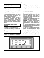
Measurement values and alarm states
are indicated by the four digit display and
indicator lights. The display will also show
maximum and minimum values. The
measurement sensor input may be linear
or non-linear and it is possible scale
results over the whole measurement
range, and to set offset values. The two
standard alarm limits with normally open
relay outputs are fully adjustable. Two
additional alarm limits with transistor
controlled outputs are available to special
order, as well as analogue (4-20mA)
output, and RS-232C or RS-485 digital
serial communication interfaces.
The standard power supply voltage is
230V 50Hz, but both 24V and 12VDC
versions are available on special order. If
required, the meter can, in its standard
form, also supply the operating voltage
for analogue current outputs, additional
relay control, and strain gauge bridge
measurements.
As a result of its broad measurement
capability the DP-151 can be used
instead of a number of different meters in
many applications. These include strain
gauge and other bridge measurements,
pulse counting, control operations,
cumulative measurements, two channel
measurements, serial communication of
measurements, and with some modelscalculation.
There is also a wide variety of other
equipment available for use with the DP151
to
further
expand
possible
applications.
These
include:
PC
communication programs and equipment,
relays and additional limit controls,
converters, separators and adapters,
different
current
sources,
parallel
displays, plotters and recorders. Full
details of additional functions and
accessories are given in section 6.
Further details and information about
applications and other equipment is
available
from
Envic
or
your
representative.