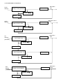
1
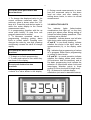
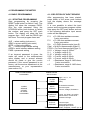
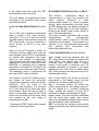
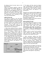
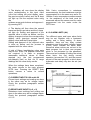
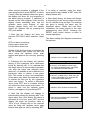
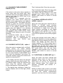
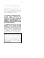
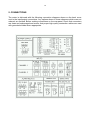
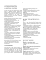
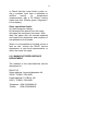
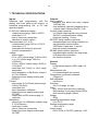
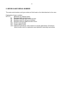
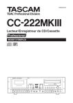
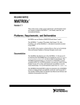
OPERATING INSTRUCTIONS
DP-151
PROGRAMMABLE PANEL METER
CONTENTS
16.04.2003 (VER 1.2)
1. GENERAL .......................................................................................................................1
2. CONSTRUCTION ............................................................................................................2
3. OPERATION ...................................................................................................................3
3.1 PUSH BUTTONS......................................................................................................................................3
3.2 INDICATOR LIGHTS................................................................................................................................4
3.3 NORMAL MEASUREMENT .....................................................................................................................5
4. PROGRAMMING THE METER .......................................................................................6
4.1 BASIC PROGRAMMING..........................................................................................................................6
4.1.1 STARTING PROGRAMMING ............................................................................................................6
4.1.2 SELECTION OF INPUT SENSOR.....................................................................................................6
4.1.3 ALARM LIMITS (Alr)...........................................................................................................................9
4.1.4 CHANGE OF MEASUREMENT RANGE (OFFS)............................................................................11
4.1.5 CURRENT OUTPUT (OP) - option 1 ...............................................................................................11
4.1.6 SERIAL INTERFACE OUTPUT (ADDR) - option 2 .........................................................................11
4.1.7 ADDITIONAL ALARM LIMIT-opt. 3..................................................................................................11
4.1.8 CHANGE OF PASSWORD (PASS).................................................................................................12
5. CONNECTIONS ............................................................................................................ 13
5.1 INPUT CONNECTIONS..........................................................................................................................14
5.2 ALARM (RELAY) OUTPUTS .................................................................................................................14
5.3 CURRENT OUTPUT (4-20mA) ..............................................................................................................14
5.4 SERIAL INTERFACES RS-232C/485....................................................................................................15
5.5 POWER SUPPLY CONNECTIONS .......................................................................................................15
6.OTHER INFORMATION ................................................................................................. 16
6.1 ADDITIONAL FUNCTIONS....................................................................................................................16
6.2 ACCESSORIES ......................................................................................................................................16
6.3 WHAT TO DO IN THE CASE OF A FAULT ..........................................................................................16
6.3.1 FAULT ANALYSIS ...........................................................................................................................16
6.3.2 MANUFACTURERS SERVICE DEPARTMENT..............................................................................17
7. TECHNICAL SPECIFICATIONS ................................................................................... 18
8. MODELS AND SERIAL NUMBER ................................................................................ 19
9. APPENDICES ............................................................................................................... 20
9.1 DATA COMMUNICATION PROTOCOLS (RS-232/RS-485) ................................................................20
9.2 RS-232/RS-485 DATA COMMUNICATION PARAMETERS ................................................................20
9.3 OPERATION AND PROGRAM FLOWCHARTS ...................................................................................21
1
1. GENERAL
The DP-151 panel meter is intended for
measurements of temperature using
either thermocouples or resistance
thermometers, and for measurement of
voltage, current, and resistance. The
meter includes a built-in programming
capability which is used for selection of
the input sensor, for setting alarm
conditions and other values. All
programming operations are done using
the display and the four front panel
membrane push buttons.
Measurement values and alarm states
are indicated by the four digit display and
indicator lights. The display will also show
maximum and minimum values. The
measurement sensor input may be linear
or non-linear and it is possible scale
results over the whole measurement
range, and to set offset values. The two
standard alarm limits with normally open
relay outputs are fully adjustable. Two
additional alarm limits with transistor
controlled outputs are available to special
order, as well as analogue (4-20mA)
output, and RS-232C or RS-485 digital
serial communication interfaces.
The standard power supply voltage is
230V 50Hz, but both 24V and 12VDC
versions are available on special order. If
required, the meter can, in its standard
form, also supply the operating voltage
for analogue current outputs, additional
relay control, and strain gauge bridge
measurements.
As a result of its broad measurement
capability the DP-151 can be used
instead of a number of different meters in
many applications. These include strain
gauge and other bridge measurements,
pulse counting, control operations,
cumulative measurements, two channel
measurements, serial communication of
measurements, and with some modelscalculation.
There is also a wide variety of other
equipment available for use with the DP151
to
further
expand
possible
applications.
These
include:
PC
communication programs and equipment,
relays and additional limit controls,
converters, separators and adapters,
different
current
sources,
parallel
displays, plotters and recorders. Full
details of additional functions and
accessories are given in section 6.
Further details and information about
applications and other equipment is
available
from
Envic
or
your
representative.
2
2. CONSTRUCTION
The DP-151 is a small compact unit
intended for flush panel mounting so that
the display and front panel push buttons
are easily accessible. The rear connector
block (for power supply inputs and relay
or other outputs), and the DIP switch on
the rear panel, are quickly accessed by
withdrawing the meter from its mounting.
The front panel display and push buttons
are sealed to class IP54 standard. The
construction is of high quality moulded
plastic and is extremely robust.
45
Panel opening
Installation dimensions
3
3. OPERATION
3.1 PUSH BUTTONS
There are three main operation levels:
A. Normal measurement - the display
updates the current measurement value,
the one program function possible is
setting of alarm limits.
B. Main program level - the front panel
push button and display are used to
select the items to be programmed, for
which values are set in the sub-programs.
C. Sub-program level - the front panel
push buttons and display are used to set
program values, alarms, and scaling of
inputs and linearization.
On the front panel of the meter there are
four membrane push buttons, which are
used in programming, in feeding in set
values, in reading stored values from the
memory, as well as in zeroing
measurement values.
Before the meter can be used in normal
measurements, it is necessary, to
connect a measurement input sensor and
to use the program to tell the meter which
sensor is being used. With some sensors
the DIP switch on the rear panel must be
set correctly - see sec 5.1. Once these
settings have been made it is only
necessary to connect power to the meter
and to read the display. If no change of
input sensor or meter usage is required, it
will normally only be necessary to make
these settings once.
The following describes the functions of
push but- tons and indicator lights, and
normal operation The next section
describes the details of programming, see
appendix for programming and operation
flow diagrams.
The up arrow push button has three
functions:
1. To change the displayed value to the
current maximum measured value. The
maximum value is shown when the “HI”
light is lit. Press this push button again to
return the meter display to the normal
measurement value.
2. In the main program to step from one
program parameter to another. In
subprograms this may also be done with
the down arrow push button.
3. To increase numerical values in
programming including setting alarm
limits or scaled values. Pressing once
changes the value by one digit, pressing
continuously causes the value to change
rapidly.
SUBPROGRAM MENUS
NORMAL
MEASUREMENT
DISPLAY
MAXIMUM
MINIMUM
ALARM LIMITS
L1 AND L2
NORMAL MEASUREMENT
MAIN
PROGRAM
MENU
ALARM
SENSOR
OFFSET
PASSWORD
OPTIONS
MAIN PROGRAM LEVEL
ALARM
PROGRAM
INPUT
SENSOR
SELECTION
/SCALING
SETTING
NUMERICAL
VALUES
SUB-PROGRAM LEVEL
4
The down arrow push button has
three functions:
1. To change the displayed value to the
current minimum measured value. The
minimum value is shown when the “LO”
lamp is lit. Press this push button again to
return the meter display to the normal
measurement value.
2. In programming (together with the up
arrow push button), to step from one
program parameter to another.
3. To decrease numerical values in
programming including setting alarm
limits or scaled values. Pressing once
changes the value by one digit, pressing
continuously causes the value to change
rapidly.
The reset push button has two
functions:
1. To begin or to finish programming.
2. To reset peak values to zero when they
are shown in the display.
The set push button has two
functions:
1. During programming, to accept or store
a choice or a value shown in the display.
2. During normal measurements, to move
from the measured value to the alarm
level set value, and after reading or
setting alarm levels, to return to normal
measurement.
3.2 INDICATOR LIGHTS
The
indicator
lights
(letter/number
combinations that light up) on the front
panel give alarms even during setting of
values and other display operations. Their
functions are as follows:
L1 and L2 - indicate alarms, and will also
light during value setting operations.
A and B - in non-linear scaling, indicate
whether the choice is the input value in
measurements (A), or the display value
(B).
Pg - indicates that programming of values
is in progress Either basic programming
or setting of alarm levels.
LO and HI - in normal operation indicate
whether the display shows peak values
(LO=minimum and HI=maximum) and at
the basic programming level indicate the
selection of upper/lower alarm limits and
lower/upper selection points in linear
scaling (LO=low level and HI=high level).
F() - is reserved to indicate display
calculation (not used in standard meters).
5
3.3 NORMAL MEASUREMENT
Press RESET to return to normal
measurement. The meter then begins to
update the measured input values in the
display.
The up arrow push button can be used to
display the current maximum value (zero
this value by pushing RESET). Return to
normal operation by pressing the up arrow
push button if RESET is not used.
The current minimum value is shown by
pushing the down arrow push button, zero
by pushing RESET. Return to normal by
pushing the down arrow again.
The HI/LO indicator lights show which of
the two peak values is shown in the
display.
If a measured value exeeds the set range,
this is indicated in the display by the OL
symbol.
In normal operation if the RESET push
button is pushed for about 15 seconds
programming can be started (see item
4,4.1).
Setting alarm limits in normal
operation:
Alarm limits can be changed with the
meter in normal operation.
Press the SET push button, and the
display changes to show the current alarm
limit 1, and both the L1 and PROG lamps
will light.
Use the up/down arrow push buttons to
select a new value or leave the old value
unchanged. Press SET and the meter
stores the value. The display then shows
limit 2 and the L2 lamp lights.Give the new
value in the same way. Return to normal
operation at any time by pressing RESET.
The DP-151 panel meter has an automatic
self-test system for checking its own
operation. In any disturbance situation the
program will try to restart normal
operation.
In meters equipped with the standard two
adjustable alarm limits, a relay contact
closure occurs when the alarm occurs.
The display indicates an alarm by L1 or L2
indicator lights, these lights go out when
the value returns to normal.
When the meter is equipped with a current
output supply or serial communication
interface, and if either is in operation, the
use of the push buttons will not affect their
operation. Alarm limits will also continue to
be valid.
When the meter is equipped with
additional alarm limits, setting of alarm
limits is done in the same way as the
standard alarms (above), but because
there are no indicator lights for these
additional limits, the display will show L3
after the L1 and L2 limits have been set
(when the L1 and L2 indicator lights
show), and then after L3 has been set, the
display will show L4 and this level is set.
As above, return to normal operation at
any time by pressing RESET.
6
4. PROGRAMMING THE METER
4.1 BASIC PROGRAMMING
4.1.1 STARTING PROGRAMMING
Start programming by pressing the
RESET push button for about 5 sec. The
display will show the message PASS.
Give the right password using the
UP/DOWN arrow push buttons to select
the number, and press the SET push
button. The display will show the first
program item - ALR, and the PROG light
will show. The main program items are:
ALR = alarm setting (sub-menu)
SENS = sensor setting (sub-menu)
OFFS = offset value setting
OP = current output values setting
ADDR = serial interface address setting
PASS = password setting
If an incorrect password is given, the
meter will return to the measurement
value display and a second attempt
should be made to give the correct
password. If the correct password is not
known, call the service department at the
manufacturers or your representative
(see section 6.2).
MAIN PROGRAM MENU
PASSWORD
4.1.2 SELECTION OF INPUT SENSOR
After programming has been started,
press either of the arrow push buttons
until the display shows the message
SENS.
It is now possible to select the input
sensor and to set sensor program values.
Now press the SET push button and one
of the following alternative input sensor
codes will be displayed:
P-3
= Pt-100 ohm resistance sensor,
3-wire connection.
P-2 = Pt-100 ohm resistance sensor,
2-wire connection.
Prh = Pt-Pt/Rh thermocouple (type S).
Chal = Ni-Ni/Cr thermocouple (type K).
FECO = Fe-Const thermocouple (type J).
U-01 = Voltage, range 0-100mV.
U-1 = Voltage, range 0-1V.
U-10 = Voltage, range 0-10V
0-20 = Current, range 0-20mA.
4-20 = Current, range 4-20mA.
r-3
= Resistance, range 0-1400 ohms,
3-wire connection.
r-2
= Resistance, range 0-1400 ohms,
2-wire connection.
SUBPROGRAM
SELECTIONS
ALARM
LIMITS
ALARM
SENSOR
OFFSET
OPTIONS
PASSWORD
High, Low, L1, L2
Hysteresis
Delay
INPUT
SENSOR
Pt Resist thermometer,
Thermocouples
Current, Voltage, Resistance
NUMERICAL
VALUES
Linear, non-linear, no scaling
Offset values, current limits
Password change
OUTPUT
OPTIONS
Current output
Serial output address
Additional alarm limits
Using the arrow push buttons, scroll up or
down to select the required input sensor code
7
in the display and then press the SET
push button to select this input.
The next phase of programming varies
according to the particular input sensor
selected as follows:
A) Pt-100 OHM RESISTANCE P-2 or P3
The Pt-100 ohm resistance-temperature
table is stored in the meter memory.
Selection of P-2 or P-3 does not require
separate scaling. After selection using the
SET push button, it is only necessary to
move directly to OFFS in the main
program.
When a 2-wire (P-2) sensor is used, it is
necessary to set an offset value using the
main program item OFFS to compensate
for sensor lead resistance. The meter
does not then display a temperature
value greater than the actual value. The
resistance of the sensor lead (WITHOUT
SENSOR) is measured with a separate
ohm-meter or with the DP-151 used in the
resistance input mode (see part E below).
The measured value is programmed as
the meter OFFS value as follows:
After selection of the P-2 display choice,
the display will show the previously
programmed resistance value (the factory
setting=0). Give the value of the
measured lead resistance to a precision
of 0.1 ohm using the up and down arrow
push buttons. When the correct value is
shown in the display, press the SET push
button and the meter will store this value
and proceed to the next stage of
programming (PASS).
Pressing the RESET push button causes
a return to normal operations.
B) THERMOCOUPLES Prh,Chal, or FECO
The millivolt - temperature tables for
thermocouples J, K, and S are stored in the
meter
memory.
Selection
of
these
thermocouples does not require separate
scaling. After thermocouple selection using
the SET push button, the display changes to
show the OFFS item of the main program.
Pressing the RESET push button causes a
return to normal operations.
The meter includes automatic cold junction
compensation
for
thermocouple
measurements (using a built-in Pt-100 ohm
resistance thermometer). This prevents any
changes in the environmental temperature
from affecting input connections and
influencing measurements.
C) VOLTAGE INPUTS U-01, U-1 or U-10
When voltage inputs are selected, after the
SET push button is pressed, the display will
show SCAL, this means that this is a
scaleable input. Scaling allows a display
readout to be given in practical units, for
example according to a linear or non-linear
calibration curve. After SCAL is shown press
SET and the display will then show one of the
following alternatives:
Lln = linear scaling. All values are directly
proportional to the display values and are
related by a constant multiplying factor.
Usr = non-linear scaling. All values are
directly proportional to the display value but
are not related by a constant multiplying
factor, instead the relation is given by a
maximum of fifteen separate pairs of inputdisplay values. The pairs are freely selectable
over the whole input range. Input values
which are intermediate between these values
are calculated by linear interpolation.
OFF = no scaling. No scaling is used and the
display shows the input value on the selected
range.
8
the display shows the input value on the
selected range.
Select the required operation using the
up/down arrow push buttons, approve it by
pressing SET. If the OFF alternative is
selected, the meter changes directly to the
main menu item OFFS because no other
selections are required in this case. When
either Lln or Usr is chosen the next stages
of programming vary according to the
choice as described below.
LINEAR SCALING
The range for scaling is over the whole
measurement reading range from -9999 to
32000 and a difference of one decimal point
is permitted between the upper and lower
set values. When a five numeral number is
set, the meter will show the four first
numerals. If the scaling range or the
decimal point difference is exceeded, the
meter will show the message OL.
1. After linear scaling has been selected,
the display will show the present position of
the decimal point dP - X (where X = 0, 1, 2,
or 3 - the number of figures after the
decimal point). Choose the number of
figures after the decimal point by using the
up/down arrow push buttons and approve
the value by pressing the SET push button.
2. The display will then show the display
value corresponding to the lowest input
value and the LO lamp will light up. Set the
required display value using the up/down
arrow push buttons and approve it by
pressing SET.
3. The display will then show the display
value corresponding to the highest input
value and the HI lamp will light up. Set the
required display value using the up/down
arrow push buttons and approve it by
pressing SET.
Scaling is now complete and the display will
change to the main menu item OFFS. If the
input greater or less than the scaled
maximum and minimum values, the display
will continue to show the scaled value
according to the set values.
Pressing the RESET push button causes a
return to normal operations.
NON-LINEAR SCALING
The scaling range is the same as for linear
scaling (from -9999 to 32000), but in this
case includes setting the input values. The
input values may cover the whole
measurement input range. The range 0 10V is programmed in volts, and the ranges
0 - 1V and 0 - 100mV are programmed in
millivolts, e.g. 1V is shown in the display as
1000.
Scaling is done in order; first for positive
values starting with the smallest input
value, and then the negative values also
starting from the smallest input value.
1. After non-linear scaling has been
selected, the display will show the present
position of the decimal point dP - X (where
X = 0, 1, 2, or 3 - the number of figures
after the decimal point). Choose the
number of figures after the decimal point by
using the up/down arrow push buttons and
approve the value by pressing SET.
2. Following this the display will show the
reading for the lowest input value (=the first
scaling set point input value) and the A
lamp will light up. Set the required input
value (e.g. 0V) using the up/down arrow
push buttons and approve it by pressing
SET.
9
3. The display will now show the display
value corresponding to this input value
(=the first scaling set point display value,
the previous stored value) and the B lamp
will light up. Set the required value using
the
up/down arrow push buttons and approve it
by pressing SET.
4. The display will then show the second
lowest set point input value and the A lamp
will light up. Setting and approval of the
required value is done as before, and the
display changes to show the corresponding
display value (previous second lowest
display value) and the B lamp lights.
Setting and approval of the required value
is done as before and the process is
repeated with the other values.
A total of fifteen input/display value pairs
may be set. Even if all possible values are
not required, it is safer to program
reasonable additional values to those
required (e.g. the last programmed
input/display pair) so that out of range
readings do not cause faulty results.
When the settings have been completed,
the meter returns to the main program
OFFS item. Pressing the RESET push
button causes a return to normal
operations.
C) CURRENT INPUTS 0-20 and 4-20
Current input settings and scaling are done
in the same way as for voltage inputs.
Check the previous paragraphs section
4.1.2.C.
E) RESISTANCE INPUTS (r-2, r-3)
Resistance input settings and scaling are
done in the same way as for voltage inputs.
Check the previous paragraphs section
4.1.2.C.
With 2-wire connections in resistance
measurements, the lead resistance must be
compensated for in the same way as for Pt100ohm 2-wire temperature measurements
i.e. the resistance of the lead must be
measured without the sensor and the value
programmed into the meter under the
OFFS item.
4.1.3 ALARM LIMITS (Alr)
Two different upper and lower alarm limits
may be set, together with a hysteresis
setting and a delay setting. In alarm
operation, there are two relay contact
operations and front panel indicator lamps
(L1/L2) which indicate the alarm state.
Numerical alarm values are not set in the
basic program, but in their own program
which is not protected by the password.
There are two methods of setting the actual
alarm limits: the first during normal
operation (see section 3.2), and the second
as part of the main program in which alarm
hysteresis and delay may also be set (see
below).
10
When normal operation is changed to the
main program level (press RESET for about
5 secs), after the password has been given,
the display will show Alr, the beginning of
the alarm setting program. If operation is
already at the main program level and the
display shows something else, use the
up/down arrow push buttons to step
through display items until the display
shows Alr. Approve this by pressing the
SET push button.
1. After this the display will show the
previous OFF/HI/LO alarm selection, these
are:
If no delay is required, press the down
arrow push button instead of SET when the
display shows dEL.
4. After delay setting, the meter will change
to the setting of the second alarm limit and
the L2 indicator lamp will light. The settings
are given in exactly the same way as
described above. When this has been
completed, the meter returns to the main
programming item SEnS. Pressing the
RESET push button causes a return to
normal operations.
The alarm setting flow diagram summarises
the process.
OFF=no alarm monitoring
HI=the upper alarm limit
LO=the lower alarm limit
Setting of the first limit value is indicated by
the L1 indicator light. Select the first limit
value using the up/down arrow push
buttons and approve the value by pressing
SET.
2. Following this the display will indicate
setting of the hysteresis value (difference
limits) by showing dB. If it is required that
the alarm returns to normal alarm operation
only after the alarm has definitely been
removed, it is possible to set a difference or
hysteresis value in relation to the alarm
limit. This cause a return and cancellation
of the alarm only when the measured value
is outside the limit set by the hysteresis
value (see figure). To select a difference
value press SET and to continue without
one press the down arrow push button. To
select a value use the up/down arrow
buttons, and approve it by pressing SET.
3. After this the display will change to
indicate delay setting by showing dEL. If an
alarm delay time (time before the alarm is
indicated) is to be set, press SET and the
display will show the previous value in
100`s of ms. Change this to the required
value by using the up/down arrow push
buttons and approve this by pressing SET.
1. SELECT HI/LO ALARM LIMIT OR OFF
2. SELECT HYSTERESIS VALUE (dB)
BY FIRST PRESSING SET, OR NONE
BY PRESSING DOWN ARROW
3. SELECT ALARM DELAY TIME (deL) BY
FIRST PRESSING SET, OR NONE BY
PRESSING DOWN ARROW
4. REPEAT WITH OTHER ALARM LIMIT
5. RETURN TO NORMAL MEASUREMENT
BY PRESSING RESET
11
4.1.4 CHANGE OF MEASUREMENT
RANGE (OFFS)
If the meter is to be set to show a greater or
lesser value than the actual input value
(constant offset) from the basic settings, the
value is set under the OFFS item in the
main program menu.
Press RESET for 5 seconds, give the
password and select OFFS using the
up/down arrow push buttons and approve
this by pressing SET. The display will then
change to show the previous numerical
value of OFFS. Now set the required offset
value in the display together with the
correct sign and approve it by pressing
SET. The display will then change to the
main program menu PASS setting. Press
the RESET push button to return to normal
operation.
As mentioned earlier, this is used to
compensate for the resistance of the
connection cable in measurements of
resistance
and
with
Pt-100
ohm
temperature sensors.
4.1.5 CURRENT OUTPUT (OP) - option 1
When the meter is equipped with a 4-20mA
current
source,
an
output
directly
proportional to the measurement value may
be obtained by programming linear scaling
into the meter memory. Press RESET for 5
secs, give the password, and select OP
using the up/down arrow push buttons and
approve by pressing SET.
1. The display will then show the previous
display value for the low (4mA) output. The
LO indicator lights. Enter the required new
value using the up/down arrow push
buttons and approve it by pressing SET.
2. The display then changes to show the
previous display value for the high (20mA)
output.
The HI indicator lihts. Enter the new value
The HI indicator lights. Enter the new value
in the same way and approve with SET.
The display will then change to the main
program menu PASS setting, press the
RESET push button to return to normal
operations.
4.1.6 SERIAL INTERFACE OUTPUT
(ADDR) - option 2
When the meter has been ordered with an
RS-232 or RS-485 serial interface
connection, measurement information may
be transmitted in digital form using the
serial interface according to the digital
traffic protocol (see section 9.1 and 9.2).
The address of the DP-151 meter is given
to the fulfil the protocol at the main program
level.
At the main program level select `Addr` in
the display using the up arrow push button
and approve this by pressing the SET push
button. The display will then show the
current address `XX`. Either accept this or
change to the required address (from 01 to
99) using the up and down arrow push
buttons and approve this by pressing the
SET push button, after this the meter
changes to main program level. Press the
RESET push button to return to normal
operation.
4.1.7 ADDITIONAL ALARM LIMIT-opt. 3
When the meter has been ordered with
additional alarm limits (L3 and L4) their
operation is the same as the standard
alarm limits (L1 and L2), but without the
alarm indicator lights. The outputs are
transistor controlled (see section 5 Connections).
Setting of alarm limits is done in the same
way as the standard alarms: limits can be
set from the normal measurement
operation, and also from the main program
12
level in which hysteresis and delays are
also set (see section 4.1.3). But because
there are no indicator lights for these
additional limits, the display will show L3
after the L1 and L2 limits have been set
(when the L1 and L2 indicator lights show),
and then after L3 has been set, the display
will show L4 and this level is set.
4.1.8 CHANGE OF PASSWORD (PASS)
The main program is protected with a
numerical password, this may be any
number from -999 to 9999. The password
programmed in during manufacture is 0. If it
is required to change this password, at the
main program menu level select the display
value PASS, and press SET.
1. The display will then show the current
password. Use the up/down arrow push
buttons to select a new number and press
SET to approve it and store it in the meter
memory. The display then changes to show
the symbol for alarm setting Alr from the
main program menu. Press the RESET
push button to return to normal operations.
WARNING!
After changing the password, it is only
possible to return to programming using the
new password. Remember to record the
new password in a safe place. If for some
reason the password is forgotten and lost,
contact your local representative or the
service department at the manufacturer
(see section 6.2).
13
5. CONNECTIONS
The meter is delivered with the following connection diagrams shown on the back cover
next to the input/output connections. Any options shown in these diagrams which were not
ordered, are omitted. Before making connections on the rear panel, check that connectors
are clean and undamaged and ensure that proper high quality connection cables are used
with grounded shields where appropriate.
14
5.1 INPUT CONNECTIONS
Pt-100 2-WIRE RESISTANCE
THERMOMETERS
The lead resistance between the sensor
and the meter should be compensated for
by programming an offset value in order to
produce accurate results.
THERMOCOUPLES
Thermocouple wires should be taken right
from the place of measurement to the meter
with the same quality of thermocouple wire
or a compensation cable. This ensures that
the automatic cold junction compensation
corrects the display reading to give the
correct temperature.
The thermocouple temperature display is
based on the DIN standard millivolt temperature tables.
CURRENT MEASUREMENTS AND
VOLTAGE MEASUREMENTS 0-10V
The input is often a 2-wire source and the
supply for this may be taken either from a
separate supply or from the meter power
supply. When the meter power supply is
used, it is connected according to the item
I+POWER shown in the diagram, other
wise it is connected the same way as in
voltage measurements - item U/I in the
diagram.
In all current measurements and in 0-10V
voltage measurements, the DIP switch on
the rear panel of the meter must be set
correctly - in the ON position, according to
the measurement being made (positions 1
or 3, positions 2 and 4 are not used with the
DP-151)
5.2 ALARM (RELAY) OUTPUTS
The standard meter has two adjustable
alarm limits L1/L2 both of which can provide
relay contact closures (max. 230V, 2A) in
addition to lighting L1 and L2.
On special order the operation direction
may also be a contact opening.
When the contacts drive an inductive load,
it is recommended that the control circuit
is equipped with an RC filter in order to
attenuate voltage peaks.
On special order it is also possible to
obtain two more alarm limits L3/L4 with
transistor outputs (max. 24VDC 0.1A).
If these outputs are used with an inductive
load (e.g. a relay), it is recommended that
a protective diode is connected in parallel
with the output circuit.
The power supply for the additional limits
may be either an external power supply or
the meters own power source. When the
meter power supply is used, remember
that the maximum output capacity is
80mA, and that allowance must be made
for other outputs which use the source
(see 5.1 and 5.3).
5.3 CURRENT OUTPUT (4-20mA)
On special order the meter can be
connected to give a current output of 420mA over a specified measurement
range.
There are two different alternative
connections depending on whether the
power source is an external one or from
the meters own power supply.
The maximum load for the output is 1
kohm, and in an overload situation the
continuous currentmay be up to 25mA.
Current output connections when using an
external and the built-in power supply are
as shown in the following diagram.
15
NOTE: The input to units connected to the current output must not be at the same
potential as the DP-151.
EXTERNAL SUPPLY
BUILT-IN SUPPLY
5.4 SERIAL INTERFACES RS-232C/485
5.5 POWER SUPPLY CONNECTIONS
On separate order the meter may also be
supplied with either an RS-232C or RS-485
serial digital interface. The RS-232 connection
uses a plug-in contact on the rear panel of the
meter. The normal maximum distance from
the DP-151 in such an application is 15m and
it is intended for connection to one unit only.
However longer cables may be used provided
that the load capacitance is not greater than
2500 picofarads. The RS-485 connection uses
the screw connectors on the rear panel of the
meter (S+ and S-).
The maximum distance is then about 300m
and multiple connections may be used. If a
greater distance is required, electrical isolation
of the data bus or use of a buffer memory will
be necessary (accessories are available for
this purpose).
The meter may be ordered with either a
230V 50Hz mains power input or a
24VDC (12VDC) input. In the 12VDC
version, current output operation will
only operate with an external power
supply.
In both of these alternatives, the DP-151 data
communication rate is 1200 Baud and
according to the standard protocols and
include the transfer of binary serial data and
stop start signals (see section 9.1 and 9.2).
Fuse protection prevents damage to
measurement and programming circuits
if there is severe disturbance on the
power supply input. The fuse is situated
on the rear panel of the meter.
Nominal power consumption of the
meter is 4W and the variation in the
power supply voltage may be ±10%
max. of the nominal value.
If the mains power source is subject to
fluctuations due to large loads, it may
be necessary to use a mains filter.
With DC power supplies, check that the
source is stable and free of pulses or
mains ripple.
16
6.OTHER INFORMATION
6.1 ADDITIONAL FUNCTIONS
The DP-151 has been designed for a wide
range of different special applications,
precise details of these will be found in the
operating instructions for the particular
version concerned of the meter. The
following is simply a list of the models for
different applications:
-Bridge measurements (e.g. strain gauges
and loading measurements).
-Pulse inputs (e.g. flow, number, and
energy measurements).
-Compensation measurements (e.g.
temperature compensation in pH
measurements).
-Display with calculation (e.g. load/speed
measurements, long term mean values,
efficiency measurements).
-Control operations (e.g. ON/OFF and
analogue control, mixing ration control,
multi-step control, frequency/pulse rate
control).
-Cumulative measurements (integrated
number measurements with analogue
communication).
-Serial interface applications (e.g. remote
monitoring of PCs, serial
transmitter/receiver units and sampling
analysis measurements).
And with the DP-152 (two channel meter)
-Two channel measurements (sum,
difference, ratio, factor in arithmetic
calculations).
6.2 ACCESSORIES
There are also a wide range of options and
accessories, some of which may be built-in,
which are available for use with the DP151. Such accessories are also provided
with their own operating instructions which
give complete details. Accessories include:
-PC communication programs and
equipment.
-Relay units with additional limit controls.
-Serial converters, separators and
adapters.
-Different current sources.
-Parallel displays, plotters, recorders.
-Transmitters, sensors, and measurement
converters.
6.3 WHAT TO DO IN THE CASE OF A
FAULT
Prior to any attempt at fault finding check
that the following operational conditions are
correct:
-Mechanical condition, no obvious damage.
-Connections, properly made and good
ground (compare with connection diagram).
-Power supply, correct voltage and
tolerances, minimum ripple with DC
supplies.
-Electrical loading, max. of 80 mA at
24VDC allowing for output and additional
relays, also max. loading for alarm output
circuits and current output.
-Program settings, input/output limits,
scaling etc.
-DIP switch settings
6.3.1 FAULT ANALYSIS
Display is completely dark:
Check the fuse and the power supply
voltage.
Display has stopped and programming
is not possible:
Disconnect the meter from the power
supply and then reconnect.
Display incorrect or OL (= overload):
a) Check the sensor and the sensor lead.
b) Check the settings on the DIP switch an
the programmed values.
17
c) Check that the meter holds a value i.e.
use a constant input from a calibrated or
artificial
sensor
(in
temperature
measurements with a Pt-100ohm sensor
make sure that 100ohm gives 0 degrees C
in the display).
Other operational faults:
a) Check program settings.
b) Disconnect the power from the meter
and open the rear panel (4 screws). Withdraw the panel and the boards attached
and inspect the attachment and condition of
components on the boards.
When it is not possible to find and correct a
fault on site, contact the ENVIC service
department, or your local representative, or
return the meter for repair.
6.3.2 MANUFACTURERS SERVICE
DEPARTMENT
The address of the manufacturers service
department is:
ENVIC OY
Street address: Lemminkäisenkatu 46,
20520 TURKU, FINLAND
Postal address: P O BOX 100
20521 TURKU, FINLAND
Telephone: +358-02-48082400
Telefax:
+358-02-48082404
18
7. TECHNICAL SPECIFICATIONS
Inputs:
Selection and programming with the
display and front panel push buttons, or
handheld programming unit, or PC with
special program.
Pt-100 ohm resistance sensor
-measurement range -200 to +850°C
-resolution 0.1°C
-two or three wire connection
-absolute or relative values
Thermocouples (J,K, or S)
-measurement range -260 to +1760°C
-resolution 0.1°C
-automatic decimal point and cold
junction compensation
Voltage
-three ranges
-10 to +10V (whole range -9.99 to +25V)
-1 to +1V (whole range -999.9 to
+2500mV)
-100 to +100mV (whole range -99.99 to
+120.0mV)
-resolution 1mV, 100uV, or 10uV, range
dependent
-input impedance >100 Mohm, except 0
to 10V>100kohm
-linear/non-linear display scaling and
OFFSET
Current
-two ranges, 0/4 to 20mA (whole range
-9.99 to +25.0mA)
-resolution 2uA
-input impedance 100ohms
-linear/non-linear display scaling and
OFFSET
-output with 24VDC power supply (if
required)
Resistance
-range from 0 to 1000ohms (whole range
0 to 1400ohms)
-resolution 0.1ohm
-two or three wire connection
-linear/non-linear display scaling and
OFFSET
Outputs:
Alarm outputs
-standard, two alarm limit relay outputs
(230VAC 2A)
-two additional (optional) transistor drive
outputs (open collector 24VDC 0.1A)
Current output (optional)
-4 to 20mA output signals using internal
(24VDC) or external power supply
-maximum loading 1 kohm
RS-232C serial interface (optional)
-standard digital short range interface for
asynchronous communication
-1200 Baud, 8 data bits, 1 stop bit
-three pin socket connection
RS-485 serial interface (optional)
-standard digital interface for long range
multi-drop communication
-two screw connector
General:
Display
-4 digit seven segment LED, height 14
mm
Measurement rate
->5 measurements per second
Temperature coefficient (ambient)
->50ppm/°C
Self-calibration
-continuous
Precision
-±0.1% of range, ±1 digit
Case
-96 x 48 mm flush mounting case per
DIN standard, front panel sealed (IP54),
flush mounting depth 120mm.
Weight
-300g
Operating temperature range
-0 to +60°C
Storage temperature range
- -40 to +85°C
Power supply
-230V, 50Hz, or 24VDC (optional) +10%
19
8. MODELS AND SERIAL NUMBER
The meter serial number and type number will be found on the label attached to the case.
Explanation of type numbers:
DP-151
Standard one channel meter
-C
Equipped with current source
-S2 Equipped with RS-232C serial interface
-S4 Equipped with RS-485 serial interface
-E2 Equipped with two additional alarm limits
-P24 Power supply 24VDC
-P12 Power supply 12VDC
-XXX Additional operational code number for special applications (XXX=three
letter/number code for explanation see application operating instructions
20
9. APPENDICES
9.1 DATA COMMUNICATION PROTOCOLS (RS-232/RS-485)
Measurement information may be transferred from the DP-151/152 using RS-232/RS-485
serial data transfer protocols to an external device which is assumed to be a PC. The PC
may be set for data communication using the DOS command `Mode´ according to the data
transfer rate and characteristics of the meter (see below). Data is transferred according to
the following scheme:
1. Starting communication
PC sends: ?XXCR
XX = DP address
CR = carriage return
DP replies: !XXCR
2. Request for measurement data
PC sends: #XXYPCR
# = start symbol
XX = DP address
Y = Channel ID (A or B)
P = Measurement data ID
DP replies: #XXY*XXX.XXL*XXX.XXH*XXX.XXCR
* = sign (+ or -)
After Y the most recent measurement result
After L the minimum value
After H the maximum value
Or overflow #XXY -999.9 if the measured value lies outside the measurement range.
Or request for repeat ?XXCR
NOTE 1. In all situations both the DP and the PC may request a repeat of the data.
NOTE 2. After maxima and minima are given the values are zeroed.
9.2 RS-232/RS-485 DATA COMMUNICATION PARAMETERS
At the rear of the meter there is a three contact plug for the RS-232 connection or the two
terminal screw connector for the RS-485 connection. A second interface may only be used
when requested on ordering. The data transfer rate is 1200 baud, 8 data bits, 1 stop bit.
The maximum frequency of requests for measurement information is 1 Hz.
9.3 OPERATION AND PROGRAM FLOW CHARTS
21
A NORMAL OPERATION
CURRENT MEASUREMENT VALUE DISPLAY
∇
PRESS
XXXX
Lo
Min value display
∆
PRESS
PRESS
L1
XXXX
Hi
Max value display
Zero with RESET
SET
XXXX
Level L1
Set point
Pg
Change
∆/∇
Zero with RESET
PRESS
L2
SET
XXXX
LEVEL l2
Set point
Pg
Change
∆/∇
PRESS
SET
L3
Pg
XXXX
Level 3
Set point
Pg
Change
∆/∇
PRESS
SET
L4
Pg
XXXX
Level 4
Set point
Pg
Change
∆/∇
PRESS
∇
PRESS
∆
PRESS
SET
B) PROGRAMMING MAIN LEVEL
NORMAL MEASUREMENT OPERATION
PRESS
RESET
Display PASS
∆
PRESS
RESET
Wrong Password
PRESS
RESET
∇
SET
RESET
PRESS
SET
Display
Alr
(Alarm settings)
Pg
Display
SENS
(=Sensor settings)
RESET
Display
OFFS
(=Offset value)
PRESS
SET
Alarm
subprogram
∆
Pg
PRESS SET
SENSOR
selection
subprogram
PRESS SET
OFFSET
subprogram
∆
PRESS
PRESS
Give Password with
∆ / ∇ Buttons
DISPLAY 0000
PRESS
PRESS
RESET
Pg
PRESS
∆
(option)
PRESS
RESET
Display
OP
(=Output scaling)
PRESS
PRESS
RESET
Display
Addr
(=Serial address)
PRESS
PRESS
RESET
Display
PASS
(Password setting)
PRESS
Pg
PRESS SET
OP (Output)
subprogram
PRESS SET
ADDRESS
subprogram
PRESS SET
PASSWORD
subprogram
∆
Pg
∆
Pg
∆
C) PROGRAMMING SUB-MENUS
PASS
Settings
XXXX
Pg
Display current password
PRESS
RES
Main Menu
ALR
RES
Main Menu OP or
PASS
RES
Main Menu
Addr
Change ∇ / ∆
PRESS
OFFS
Settings
SET
X.XX
Pg
Display OFFSET-value
PRESS
Change
PRESS
OP
Settings
L1
∇/∆
SET
PRESS
Display XXX.X
Pg
4mA scaled value Lo
(OPTION)
Change ∇ / ∆
PRESS
SET
L2 Display XXX.X
Pg
20mA scaled value Hi
PRESS RES
Change ∇ / ∆
PRESS
Addr
Settings
SET
XX
Pg
Display current address
PRESS
(OPTION)
Change
PRESS
SET
∇/∆
RES
Main Menu
PASS
Main Menu SENS
ALR
Settings
L1
Display L1 level
OFF, HI or LO
Pg
PRESS
RES
∇/∆
Change
PRESS SET
L1
Display
db
Pg
(=L1 level hysteresis)
PRESS
L1
XX.X
Pg
Display Current Hysteresis
press ∇
PRESS
L1
Display
SET
DEL
Change ∇ / ∆
SET
Pg
PRESS SET
L1
L1
Display
Input delay x 0,1s
Pg
Change ∇ / ∆
PRESS SET
L2
Display L2 level
OFF, HI or LO
PRESS
Pg
Change
RES
∇/∆
PRESS SET
L2
Display db
(=L2 level hysteresis)
PRESS
Pg
L2
XX.X
Pg
Displayed Current Hysteresis
PRESS ∇
PRESS
L2
Display
DEL
SET
Pg
PRESS SET
L2
L2
Display
input delay x 0,1s
Pg
Change ∇ / ∆
PRESS SET
L3,L4 levels
(optio)
YES
SET
NO
(See next page)
Change ∇ / ∆
Display L3
(1. optio level)
PRESS
Pg
Pg
Pg
PRESS
SET
XX.X
Pg
Display Current Hysteresis
∇
PRESS
Display DEL
SET
Change
∇/∆
Pg
SET
Display L3
Input delay x 0,1s
Pg
Change
∇/∆
SET
Display L4
PRESS
RES
SET
Display
db
(=L3 level hysteresis)
Press
PRESS
Main Menu SENS
∇/∆
Change
PRESS
PRESS
RES
SET
Display L3 level
OFF, HI or LO
PRESS
PRESS
Pg
PRESS
RES
PRESS
RES
SET
Display L4 level
OFF, HI or LO
Pg
Change ∇ / ∆
PRESS
SET
Display db
Pg
(=L4 level hysteresis)
PRESS SET
XX.X
Pg
Display Current Hysteresis
PRESS ∇
PRESS
Display DEL
SET
Change
Pg
PRESS SET
Display L4
Pg
Input delay x 0,1s
Change
PRESS SET
∇/∆
∇/∆
SENS
sett.
Display
Pg
Current input sensor
PRESS
RES
Change ∇ / ∆
P-3=Pt-100ohm 3-wire
1)
P-2=Pt-100ohm 2-wire
Prh=PtRhPt Thermoc.
Chal=NiCrNi Thermoc.
PRESS SET
PRESS SET
PRESS SET
PRESS SET
FECO=FeConst
Thermoc
PRESS SET
V-01=Voltage 0-100mV
PRESS SET
V-1=Voltage 0-1V
V-10=Voltage 0-10V
0-20=Current 0-20mA
4-20=Current 4-20mA
r-3=Resistance
0-1400ohm 3-wire
r-2=Resistance
0-1400ohm 2-wire
SCAL Pg
PRESS SET
PRESS SET
PRESS SET
PRESS SET
PRESS SET
PRESS SET
PRESS SET
1) If scalable input is selected as OFFS, the instrument indicates
the input value in Volts, mA`s or Ohms.
In Pt-100 2-wire measurements lead resistance must be set as
OFFS-value.
Over range situation is indicated by OL in display.
Display
Current
Scaling type
Change
∇/∆
LIN
Pg
PRESS SET
Usr
Pg
PRESS SET
OFF
Pg
PRESS SET
Main Menu OFFS
Change
∇/∆
PRESS
dp 0-3
Pg
SET
PRESS
SET
XXXX
Lo
Pg
Current low. point
Hi
Pg
Current hi. point
Change
∇/∆
Change
∇/∆
XXXX
PRESS SET
Display Current
Des. point
Display Currrent
Des. Point
PRESS
A
dp
0-3
Pg
SET
XXXX
PRESS
Pg
Current lowest
input point
B
SET
XXXX
Current low. point
in display
Change
∇/∆
Change
∇/∆
Pg
Change
∇/∆
PRESS SET
PRESS SET
Max 15 Settings pair