1
Synfig Studio 0.62.01 User Manual
2
Chapter 1
Introduction
1.1
Overview
Synfig Studio is open-source 2D vector animation software. It is designed to produce
film-quality animation with fewer people and resources.
According to Wikipedia, animation is the rapid display of a sequence of images
in order to create an illusion of movement. Traditionally 2D animation is created
by drawing each displayed image individually. Those images are called "frames"
and thus such method called "frame-by-frame animation". To create good illusion of
movement you need to draw many frames, that’s why his method requires a lot of
time and resources.
Synfig Studio is built to eliminate the need to draw each frame individually. There
are two techniques for that:
• Morphing animation
• Cutout animation
Morphing is a technique that takes two images and creates a smooth transition
between them. In the process of transition one shape is deforms to another and this
deformation is usually defined by control points. In Synfig Studio images constructed
from vector shapes and the morphing is done in automatic way. That allows to create
animation by drawing only key positions at relatively wide time intervals. Artist can
draw as many frames as he need to create basic sense of motion for the scene and
Synfig Studio takes responsibility to create in-between frames.
Cutout animation is created by splitting objects into parts and applying some
simple transformations to them (like translation, rotation or scale) at different moments of time. Synfig Studio uses those values to interpolate the motion for inbetween frames. Cutout animation can be produced from bitmap images or vector
graphics.
3
4
CHAPTER 1. INTRODUCTION
In both cases the role of Synfig Studio is to fill the gaps between drawn frames
(also called "keyframes") to produce smooth and fluid animation. This process is
called "tweening". But tweening is not the only advantage of Synfig Studio.
Although Synfig Studio is not directly intended to draw animation frame-byframe, it can be used to bring your hand-drawn frame-by-frame animation to the
film-quality level. That’s achieved by converting bitmap data of each frame to vector format. This process is called "tracing". There are lot of effects built into Synfig
Studio allowing to achieve a professional look for your animations.
Whether you do frame-by frame animation or not, Synfig Studio can give you
flexible control over the repeated data, such as colors, outline characteristics, textures,
images and many more – even animation trajectories and their sets (actions). Reusing
repeated data is achieved via linking. It is power of Synfig Studio, which is especially
important for big animation projects.
You can not just link pieces of artwork data, but also define relations between
them using a set of functions. That allows to create automatic animation based on the
defined laws and bring whole animation process to the new level.
To crown it all, Synfig Studio is powerful software targeted on creation of animation of any complexity.
Chapter 2
Diving In
2.1
2.1.1
Getting Started
Introduction
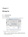
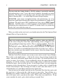
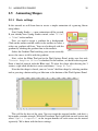
When you start Synfig Studio, you will see windows like on screenshot below.
Figure 2.1: Default interface layout of Synfig Studio
The main components of the Synfig Studio interface are:
• Toolbox — is the main Synfig Studio window. Closing that window means
exiting from application. It contains system menu and buttons, tools and more
to create and edit your artwork.
5
6
CHAPTER 2. DIVING IN
• Canvas — this is is where your artwork and animations will appear.
• Panels — contain tools and information about certain elements of your project.
Some panels will even allow you to modify those elements.
Note
If your Synfig Studio interface layout looks different, fortunately the arrangement shown in the screenshot is pretty easy to recover. In the "File"
menu from the Toolbox select "Panels" → "Reset Windows to
Original Layout".
The window at the center is called Canvas Window. Each time you start Synfig
Studio, a new Canvas Window is opened. This window represents the Root Canvas,
not that that means much to you at the moment, but that’s OK — We’re just trying
to show you around. In the upper left corner of the Canvas Window, you’ll see a
button with a caret. If you click on this caret button, the canvas window menu will
pop up. (By the way, if you right-click in the canvas area and there is not a Layer
under the mouse position, this menu will also appear.) So now you know where the
most important canvas menu is, right in the Canvas Window. Good.
The other two windows (one on the bottom, and one to the right) are customizable
dock dialogs. Each dock dialog contains a set of panels, arranged horizontally or
vertically. Some panels share the same space inside the dock dialog and you can
switch between them by clicking on their tabs. You can rearrange the contents of
dock dialogs as you wish by dragging the panel tab to where you want it. You can
even create a new dock dialog by dragging a tab out of its dock dialog.
If you accidentally close a panel (by dragging it out of the dock dialog, and closing
the new dock dialog that gets created), no worries. Simply go to the Toolbox, select
"File" → "Panels" in toolbox menu and then click on the name of the panel
you need.
The most important panels are:
• Layers Panel — This panel shows you the hierarchy of layer of your working
canvas. It also allows you to manipulate these layers.
• Params Panel — This panel shows you the parameters of the layer currently selected. When multiple layers are selected, only the parameters that the selected
layers have in common are displayed.
• Tool Options Panel — This panel shows you any options specific to the currently selected tool.
• Navigator — This shows a thumbnail image of what the currently selected canvas looks like. You can also zoom in and move the focus around with this
panel.
2.1. GETTING STARTED
7
• History Panel — This shows you the history stack for the current composition.
You can also edit the actions in history.
There are many panels in Synfig Studio. If you have no idea what a panel does,
simply hold your mouse over its icon and a tooltip will pop up describing its function.
2.1.2
Under the hood
Synfig Studio, like most every other competent graphics program, breaks down individual elements of a canvas into layers. However, it differs from other programs in
two major ways:
1. An individual layer in Synfig usually represents a single "Primitive". I.e. a
single region, an outline of a region, an imported image, etc. . . This allows
you to have a great deal of flexibility and control. It is not uncommon for a
composition to have hundreds of layers (organized into a hierarchy for artist’s
sanity of course).
2. A layer can not only composite information on top of the image below it, but
also distorts and/or modify it in some other way. In this sense, Synfig’s Layers
act much like filters do in Adobe Photoshop or the GIMP. For example, we have
a Blur Layer, Radial Blur Layer, Spherize Layer, Color Correct Layer, Bevel
Layer, etc. . .
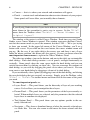
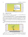
Each layer has a set of parameters which
determine how it behaves. When you click on
a layer (either in the canvas window, or in the
illustrated Layers Panel), you will see its parameters in the Params Panel.
Synfig Studio has an autorecovery feature.
If it crashes, even if the current file has not been
saved, it will not lose more than 5 minutes of
work. At restart it will automatically prompt
the user to recover the unsaved changes. Unfortunately history isn’t recovered yet.
2.1.3
First steps
Let’s create something fun so that we can play
with it!
First, go over to the toolbox and click on
the Circle Tool (if you don’t know which one it
is, just mouse over them until you find the one
with the tooltip that says "Circle Tool").
Figure 2.2: Layers Panel
8
CHAPTER 2. DIVING IN
Development Notes:
You may find that Synfig Studio is SLOW, making it practically unusable
on hardware that is over 3 years old even if it behaves acceptably on recent
hardware. The biggest reason for this is that all of the color calculations are
done in floating point — to enable High-Dynamic-Range Imaging.
HOWEVER, some major re-implementations and optimizations are to be
made that should quite dramatically improve the performance of Synfig on all
platforms. The goal is not a 200% speed increase, but at least a 2000% speed
increase. Currently there is a work in progress in development branch implementing those optimization via OpenGL. It already shows very promising
results, but is not ready for usage yet.
When you click on the circle tool, you should notice that the Tool Options Panel
changed. But we’ll get to that later.
Note
Some users might experience the following problem: when you click-drag
on the canvas using the Circle Tool, either nothing seems to happen or you
end up making insanely huge circles. This is a known problem. To fix this
go to "File" → "Input Devices" and disable all the devices you
can find there (such as Macintosh mouse button emulation or USB Optical
mouse). If you have an extended input device that you want to use, such as a
pressure-sensitive pen, then enable it in this screen. After this change Synfig
will work as expected.
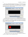
With the Circle Tool selected, you can now create circles in the Canvas Window.
This works as you might expect — click on the canvas, drag to change length of the
radius, and release the mouse button when you are done. Go ahead and create two
circles (or more, if you fancy). If you accidentally release the mouse button before
dragging, you end up creating a circle with 0 radius and it is effectively invisible!
No need to worry, you can easily fix this. In the Params Panel, you can change the
parameters of the selected object. If you just made a 0 radius circle, it should be the
current selected object. You can change its radius to some value other than 0, say 10,
and manipulate it to your liking with the canvas ducks later.
Now go back to the toolbox and click on the Transform Tool (the blue circle with
the arrow on it). After you do this, click on one of your circles. You will then see a
Bounding box (which is kind of useless at this point in time, but I digress), a green
dot at the center, and a cyan dot on the radius. Those dots are called ducks. If you
want to modify the circle, grab a duck and drag it around. Easy!
2.1. GETTING STARTED
9
You can select a Layer by clicking on it. If you want to select more than one layer,
hold down Ctrl key while you are clicking — this works in both the Canvas Window
and the Layers Panel. Try it!
You can also select multiple ducks. You can do this in several ways. First, you
can hold down Ctrl and individually click the ducks that you want selected, but this
can be tedious. However, there is a much faster method — just create a selection box
by clicking the mouse and dragging it over the area of ducks that you want selected.
Go ahead, select two circles and select all of their ducks. With several ducks
selected, moving one duck will move all of the ducks. This behavior is dependent on
the Transform Tool. Thus, a more descriptive name for this tool might have been the
"move" or "translate" tool.
The rotate and scale tools work much like the Transform Tool, except in the case
where you have multiple ducks selected. It is much easier to just try it than read about
it. Select a few circles, select all of their ducks, and try using the rotate and scale
tools.
Note that, duck manipulation tools have options associated with them. If a particular tool isn’t doing what you want, take a look in the Tool Options Panel to see if it
is set up the way you want.
2.1.4
Linking
Now let’s try linking. Let’s say we always want these two circles to be the same size.
Select two circles, and then select both of their radius ducks (the cyan dots).
To select multiple ducks, either drag a rectangle around them, or select the first
one, then hold the Ctrl key while selecting the rest. Once you have the two radius
ducks selected, right click on either duck and a menu will pop up. Click on "Link".
Boom. The parameters are linked together. You can prove it to yourself by selecting
just one of the circles and changing its radius — the other one will change as well.
Neat stuff, eh?
Linking is a fundamental concept in Synfig. You can create links not only between
ducks, but also between parameters as well by selecting multiple layers, right clicking
on the parameter in the param tab, and selecting "Link".
Digression
This is how outlines are attached to their regions — but I’m getting ahead
of myself. At the moment, the fundamental power and flexibility of linking
in Synfig Core is beyond what Synfig Studio currently allows for. This will
change in the future. Anyway, back on track. . .
10
2.1.5
CHAPTER 2. DIVING IN
Color selection
Let’s say you want one of the circles to be a different color. If you look in the toolbox
below the tools, you’ll see the outline/fill color selector, the outline width selector,
and some other stuff like the default blend method and gradient. The outline/fill color
widget works exactly as you might expect — you can click on the fill color, and a
modest color chooser will appear. Now to can change the color pretty easily.
But sometimes you just want to click on a color and go. This is where the palette
editor tab comes in. Its functionality isn’t quite 100% yet (ie: saving and loading
custom palettes hasn’t been implemented yet), but the default palette is pretty decent.
Click on the Palette Editor panel tab and have a look — it’s the one with the palette-ish
looking icon. Clicking on colors with the left mouse button will immediately change
the default outline color and clicking with the middle mouse button will change fill
color.
That’s all great, but we still haven’t changed the color of the circle. There are
three ways to do this. The first is to select the circle layer you want to modify, go
to the Params panel and double-click on the "Color" parameter. A color selector dialog will then show up, and you can just tweak away. But let’s say you already selected your color as the default fill or outline color. Then you can right-click
on the Color parameter in the Params panel and select "Apply Fill Color" or
"Apply Outline Color" at you preference. Finally, you can just click on the
"Fill Tool" from the toolbox, and then click on the circle in the canvas window.
Boom. Circle changes color. This works with more than just circles, but we’ll get to
that in a sec.
Try playing around with the circles for a bit. Muck around with the parameters,
and see what happens. To get you started, try out to set the Feather Parameter to 5.
2.1.6
Digging deeper
Of course, so far you just found out how to use the basic features of Synfig Studio but
not how you animate a drawing. This is covered in the next chapter.
2.2
2.2.1
Animation Basics
Introduction
Creating an animation in Synfig Studio is really easy. It basically means to change
a drawing — you just need to create the first stage and last stage of a change, and
Synfig will take care of the steps in between.
Let’s see a simple example. Consider a moving light like the one at the front of
the Knight Rider car. Drop the realism, you get a circle moving from left to right and
back. In other words, you need to create three ’steps’ or ’stages’:
2.2. ANIMATION BASICS
11
1. The circle is on the left.
2. The circle is on the right.
3. The circle is back on the left.
Let’s do it.
2.2.2
Setting up the workspace
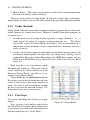
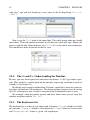
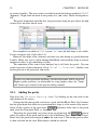
Start Synfig Studio. New file is automatically created at the start. Click the ’caret’
menu (between the horizontal and vertical rules, in the top left hand corner of the
canvas), then select "Edit" → "Properties". A canvas properties dialog will
appear.
Development Notes:
The canvas properties dialog is a mess, we know. We will have it re-designed
into something much more comprehensible some time in the future. For now,
ignore the "Image Area" and "Locks and Links" sections.
Give a name and description for your canvas, then click "Apply" (don’t click
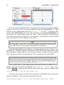
"Save" yet — we’re not quite done with the ’Properties’ dialog). Go to the "Time"
tab and make sure to edit "End Time". Change ’5s’ to ’2s’ — that will make our
animation to be 2 seconds long.
Figure 2.3: Canvas Properties Dialog
12
CHAPTER 2. DIVING IN
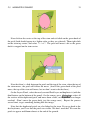
Now create a simple black rectangle that will serve as our background. It’s not
necessary to make it cover the whole canvas. Also, uncheck "Low Res" checkbox
at the top of the canvas window to disable low resolution view mode – that will make
your image look sharper. Generally, having that option enabled increases canvas redraw speed, but that’s not what we need now.
We now need a circle. Change the fill color to red, and create a circle. It doesn’t
matter if it’s not perfect: You can edit it. Activate the Transform Tool, and click the
circle. It will go into a sort of editing mode which is easy to detect by the small green
dot in the middle and the white rectangle around it. You can move the red circle by
grapping it on its green dot in the middle.
These are the first steps to draw an object and to move it, but not yet an animation,
you may say. Indeed. Let’s have a look how this works.
2.2. ANIMATION BASICS
2.2.3
13
Adding movement
In the beginning, you entered a value of 2 seconds in the Properties dialog. Because
the length of your animation is non-zero, your canvas window (the one where you
draw) got a grey time slider at the bottom. You can click on it, and a small orange
indicator will appear indicating your position in time. Try clicking in several places
on the time slider and notice that the entry field on the left of time slider changing its
values to something like "12f", "1s 15f", etc. You can set your position on the
timeslider by changing values in that field. For example, if you enter "1s" and press
Enter , the orange indicator will move in the middle of time slider, and entering
"2s" will move it to the end of time slider.
Note
In the last case orange indicator will become invisible, because 2s is right at
the boundary of time slider, just belive me — it’s there.
But when you changing your position on the time slider nothing changes on the
canvas. This is because you need to switch to "Animate Editing Mode" first
by clicking the green dot just to the right of the grey time slider. You will note that
your canvas gets a red outline; it reminds you that changes to your objects now affect
your animation.
Previously, three ’steps’ or ’stages’ were mentioned. These are represented by socalled ’keyframes’ (Just in case you’re familiar with video encoding: No, that’s not
the same!). A keyframe is an image in time where something important happens with
your objects.
Go to Keyframes panel — just click on the little tab one with the small key icon
in the bottom window — to be able to edit keyframes. Now press the small button
14
CHAPTER 2. DIVING IN
with ’plus’ sign and you should get a new entry in the list displaying "0f, 0f,
(JMP)".
Now, go to the "1s" mark in the timeslider. The small orange indicator should
move there. Then add another keyframe by clicking the small plus sign. Repeat the
process with the time slider indicator set to "2s" (it’s at the end of your animation).
You should have three keyframes in the list, now.
2.2.4
The s’s and f’s: Understanding the Timeline
By now, you may have figured out what those mysterious ’1s 10f’-type marks represent. They indicate a specific point on the timeline, expressing a location in terms of
seconds (s) and frames (f).
By default each second is divided into 24 frames, much like a meter on a measuring tape is divided into 100 centimeters. The frame markings begin at zero (0) and go
up to 24, whereupon a new second is entered and the framecount returns to zero.
For example, when five whole seconds and three frames have passed, using this
timeline notation would be "5s 3f".
2.2.5
The Keyframe List
The keyframe list is rather easy to understand. It displays "Time" which is basically
the start time, "Length" which is self-explanatory, "Jump" which we’ll cover next,
and "Description" which is, again, self-explanatory.
2.2. ANIMATION BASICS
15
Now, you might be wondering about the entries called "(JMP)". In fact, these
are links just like web links: click them, and the indicator in your timeslider will jump
to the correct time.
You can use this to edit your image for a given moment in time. For instance, you
can now jump to the first second, and move the red circle to the right. There! You
made your first movement, your first animation with Synfig!
Wondering where the animation is? Just click to an arbitrary position on the
timeslider: You will note that the red circle is in a new position, one that you didn’t
specify! So what happened? Synfig figured out what you would like to do, namely
move the circle, and drew all the images between these states. Each image will later
make a frame in your animation and the circle will appear to be moving.
Note
Notice, that you don’t need to go to the last keyframe at ’2s’ and move your
circle back to the left. Keyframes make synfig remember image state at particular time. That’s why when we modified circle position at ’1s’, it stays on
the left at ’2s’ (as well as at ’0s’). If you switch back to Params Panel, and
look at the Timetrack Panel you’ll notice a three green dots appeared on the
right of "Origin" parameter. Those are called Waypoints and they used to
indicate changes of parameter over time.
2.2.6
Rendering your animation
Before you can see your animation, you need to process (or render) your work. There
are two ways to do so: using the synfigstudio (what you have been using so far) or the
command-line program synfig.
16
CHAPTER 2. DIVING IN
Close the animate editing mode by clicking on the red dot in the timeline editing
widget, and save your file; for instance under the name BasicKnightRider.sif. Then
click the ’caret’ menu button and select "File" → "Render". Change the filename to BasicKnightRider.gif in the same location you saved BasicKnightRider.sif
and choose "gif" target format instead of "Auto", then click Render. Depending on
your processor speed it should take a few moments, but finally the image window
status bar should say "File rendered successfully".
Note
The "magick++" target (if it is available) produces much better gifs than the
"gif" target because it can optimise the palette for the image.
Open BasicKnightRider.gif in Firefox or another application that is able to show
animated gif’s. However, Firefox will replay the GIF all the time which makes your
short animation a rather long one. If you’re now seeing a red circle moving from the
left to the right and back, congratulations! You just made your first animation!
Note
You can also preview your animation. Press the ’caret’ menu button in the upper left corner of the image window and choose "File" → "Preview".
If you would rather use the command line instead of the menu to render your animation, then open a terminal (on Windows, go "Start" → "Run", type "cmd"
anf press Enter ), change to the directory you saved the file, and type something like
synfig -t gif BasicKnightRider.sif
A few messages appear that don’t matter right now. Depending on your processor
speed it should take a few moments, but finally a line like
BasicKnightRider.sif ==> BasicKnightRider.gif: DONE
2.3. ADDING LAYERS
17
Warning!
The version you are using may not support the GIF output format at the
moment, it depends on the version and compilation settings.
should appear, then you are done and can view your animated gif using firefox or
another program as mentioned above.
2.2.7
Conclusion
Of course, the position of an object is not the only thing you can change with Synfig
Studio. Other possibilities incude its size, its outline, its color, etc. Synfig comes with
several example files that should let you dig deeper into the possibilities.
2.3
2.3.1
Adding Layers
Introduction
In the previous tutorial, you made your first simple animation by changing the attributes of primitive objects, such as: position, color, and size. These simple types,
however, are seldom sufficient to create advanced characters and objects. To do so,
Synfig uses layers. They are similar to layers used in other drawing applications in
that they are used to separate different elements of an image.
However, Synfig’s layers are different from layers in other programs in at least
three respects:
1. Every object, element, and effect gets its own layer.
2. You can organize layers into hierarchical groups.
18
CHAPTER 2. DIVING IN
3. You can use upper layers to change the behavior (or look) of underlying layers.
As you will see, layers are an extremely important aspect of Synfig, much more
so than most graphics programs. Understanding the concept of layers is an important
part in understanding how Synfig works.
2.3.2
Combining layers
So let’s look at a simple example of how we can combine two layers to create a
gradient effect on a rectangle.
Create a new file with 0 duration. There’s no need to bother with a timeline at this
point. Next, create a simple rectangle with the Rectangle Tool.
Pick the Gradient Tool from the Toolbox, press left mouse button on the canvas,
drag to change gradient direction and release button when you are done. You should
note that another layer was added in the Layers Panel called Gradient. This is nothing
special.
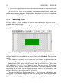
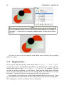
You now have a gradient, but it is not what you wanted: it spreads across the
whole canvas. The goal was to have a gradient in the rectangle. So, let’s fix this now.
In the Layers Panel, select both the gradient and the rectangle layer. Then, rightclick and select "Encapsulate" from the menu. The view of your Layers Panel
should change now, showing a small box called Inline Canvas with an arrow in front.
By clicking on the arrow you can expand the inline canvas to see its contents, your
previous two layers: the gradient and the rectangle.
You can treat this layer like any other layer — move it around, duplicate it, copy
and paste it. If you want to change the name of it to something more descriptive, just
select the layer in the layer tab and click on its label. Then you just edit it in place.
You can do this for ANY layer, and are strongly encouraged to do so.
2.3. ADDING LAYERS
19
Note
If you see no gradient but just a plain color, that means that you probably
just clicked on the canvas without dragging your mouse. To fix that pick the
Transform Tool, click into the canvas to activate the gradient’s ducks. You
need to grab the one you see and move it a bit until a gradient appears.
2.3.3
Using locality
However, there is still a problem: the gradient still covers the whole canvas although
we wanted it to be restricted on the rectangle. To do so, activate the gradient layer
in the Layers Panel. Now go to the Params Panel (by default it resides in the bottom
window), and search the attribute called "Blend Method". Double-click the entry
and select "Onto" from the drop-down menu.
The gradient should now be restricted to the rectangle. Congratulations! You just
made your first effect by interacting layers with Synfig.
If only for the additional organization, encapsulating layers into inline canvases
dramatically improves the ease of use of Synfig Studio. But lots of programs can do
this. The concept of scope as just demonstrated sets Synfig apart from other programs
with layer hierarchies. The key point is that layer can only modify the data that it
20
CHAPTER 2. DIVING IN
gets from directly below it. In other words, if you were to throw a Blur Layer on top
of the layers inside the inline canvas we created, it would just blur them — anything
under the inline canvas would not be blurred! Let’s try it.
2.3.4
Using layers to modify other layers
Make sure you have Inline Canvas layer selected and create two red circles. They will
appear on top of Inline Canvas. Select Inline Canvas layer and use "Raise Layer"
button in the Layers Panel to place it on top of the circles.
2.3. ADDING LAYERS
21
Now our inline canvas layer (with rectangle and gradient) is in front of those two
circles.
Expand the inline canvas to show its contents, and select the top layer inside of it
(should be the gradient layer). This is where we want to insert the new layer. Create
another circle filled with a black color. The black circle layer will be created over the
gradient layer inside the inline canvas.
Now, right click on the black circle layer in the Layers Panel and a popup menu
will appear. The first item in that popup is "New Layer". Inside of the "New
Layer" menu, you’ll see several categories of layers you could create, but what we
want is a blur, so go to the Blurs category and select the "Blur" layer (so that would
be "New Layer" → "Blurs" → "Blur").
Well, it blurred. . . but something is not quite right — the outside edge of contents
of the inline canvas is still sharp. It is doing this because the blend method of the
blur defaulted to "Composite" (you can change the default blend method for new
layers from the New Layer Defaults section of the Toolbox). What we want is a blend
method of "Straight". Just select the blur layer, and change the Blend Method to
"Straight" in the Params Panel.
22
CHAPTER 2. DIVING IN
Note
We will probably change the way that default blend methods are handled in
the future — as the way it is currently handled seems to only create hassles
like this.
Ok, now we have all of the contents of the inline canvas blurred, but everything
under it is sharp!
2.3.5
Digging further. . .
If you care to look into Synfig’s main menu under "Layer" → "New Layer"
you will note quite a lot of different possibilities for making layers. Several of them
sound rather unusual, like "Transform" → "Rotate" for example. You can
use this to add new attributes to your objects. And just like other, basic attributes
in the previous animation tutorial, you can change them to be different on certain
keyframes. Synfig will take care of interpolating the steps in between.
For example, you could create a some shape and add a Rotate Layer over it. Combine this with the lesson learned in the last tutorial and you can create a rotating effect.
This technique is used for creation of Cut-out Animation.
2.4. CREATING SHAPES
2.4
2.4.1
23
Creating Shapes
Introduction
Basic primitives such as circles or rectangles are all great, but they are pretty much
geometrically inflexible. What about creating more complex shapes? To do this, we
use BLine Tool.
2.4.2
BLine Tool
In Synfig, the construct for describing shapes is called a Bline. This is roughly analogous to a "path" in other programs, except that it is strictly a hermite spline.
Before we start with the BLine tutorial, let’s look at some
additional notes on how Synfig works. When you click on
the Bline Tool, you will see that the vertices from your currently selected object (if there was one) will disappear, but
the layer(s) will still remain selected in the Layers Panel.
This is normal. Anything you create with the BLine Tool will
be inserted above the currently selected layer. Keep in mind
that if you want to insert a shape somewhere, you should select where you want to insert it before you go into the Bline
Tool — changing the selection afterward will automatically
swap you back to the Transform Tool.
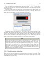
Now, go ahead and click on the "Reset Colors" button in the lower left corner of the FG/BG color widget in
the toolbox. This will reset us back to the default black and
white. Also, set the default line width to something nice and
thick — 10pt should do the trick.
Figure 2.4: Reset ColAfter you switched to BLine tool, take a look at ors button in the Toolthe Tool Options Panel. Make sure that only "Create box
Region BLine", "Create Outline BLine" and
"Link Origins" are checked.
Clicking with your mouse in the canvas will place vertices. While you are placing
a vertex, you can drag out its tangent by dragging the mouse. Do this over and over,
and you construct a Bline.
Keep in mind, however, that during this construction, there is nothing stopping
you from just moving it if you don’t like where you placed a vertex or a tangent. Honest! If you want to remove a vertex, right click on it and select "Delete Vertex".
Want to split the tangents? Right click on the tangent and hit "Split Tangents".
Want to loop the bline? Right click on the first vertex and select "Loop BLine".
So we assume you got your first BLine laid out like you want it. That’s great. But
you may have noticed that the layers have not been created yet. That’s because we are
24
CHAPTER 2. DIVING IN
still in construction mode. There are two ways to create the layers: just either switch
to another tool, or press the "Create" button at the bottom of the Tool Options
Panel (it’s the icon that looks like a gear). For now, just go ahead and click on the
Transform Tool because we are done with the Bline Tool.
2.4.3
Editing BLines
Ok, we now have a nice pretty white region with a thick black outline. Since we
checked "Create Region BLine" and "Create Outline BLine" in previous steps, you’ll notice that there are two layers that we have created — the Outline
and the Region in the Layers Panel. Despite the fact that they are two separate layers,
their vertices parameter has already been linked — so you can select either one and
move its ducks around and the other one will also change.
If you want to manipulate the vertices after you have created the layers, it is very
easy to do so. Just click on one of the layers and have at it. If you want to remove a
vertex, right click on it and hit "Remove Item (smart)". Want to insert a point
somewhere? Right click on the segment where you want to insert something and hit
"Insert item (smart)".
Note
The only major difference between this normal editing mode and the construction mode is in how you split the tangents — in construction mode you
right click on the tangent itself. In normal duck editing mode, you must right
click on the vertex that the tangents are attached to. This could be considered
a usability bug, and it will be resolved at some point.
This may appear to be leading to a mess of layers. And yes, if you aren’t using
2.4. CREATING SHAPES
25
the software properly, that is exactly what you will get. But there is a way to make
this more sane. As mentioned in the previous tutorial, you can encapsulate layers into
hierarchy.
One quick thing to mention before I finish up. You can change the width of an
outline at each vertex. You do this by selecting the outline layer (NOTE: you must
select the Outline Layer, the Region Layer has no width data) and tweaking with the
width ducks. By default, these are masked. To show them, press Alt 5 or click
"Toggle width ducks" button at the top of the canvas window (the fifth one
from the left). Repeat to hide them again. You can also see other things to mask via
the Canvas Menu Caret: "View" → "Show/Hide Ducks".
2.4.4
Using tablet to draw shapes
If you have graphic tablet you can use Draw Tool to create BLines.
Synfig Studio supports pressure sensitivity, but you need to configure it first. Go
to "File" → "Input Devices..." from toolbox menu. In the Input dialog
find your tablet’s stylus device and set its mode to "Screen". Click "Save" and
then "Close".
Now grab your stylus, create new file and click on the Draw Tool button in the
toolbox. Set default line width value to be big enough — say, 15pt — otherwise you
will not notice any pressure sensitivity effect. Choose brown as default fill color.
Note
Steps above should be done with stylus of your tablet, not the mouse. Synfig
Studio remembers settings for each input device independently. That’s why
if you set those options with your mouse device they will not have any effect
when you switch to stylus.
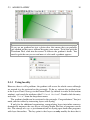
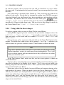
In the Tool Options Panel, make sure that you have same options as shown on
screenshot below.
Now let’s draw some thing like curvy mountain background. Start drawing a line
from the left border to the middle of the canvas. Try to vary pressure while you
drawing. Stop near the center of the canvas. This is your first line. Notice new outline
layer created in the Layers Panel.
Point your stylus at the last duck of your new BLine and continue drawing to the
right border of the canvas. When you finish, look at the Layers Panel again. There’s
still only one outline layer. Synfig Studio is smart enough to figure out that you don’t
need a new outline layer and properly extends the last one. You can extend the BLine
from both ends, but if you start drawing from any other place of the canvas a new
outline layer will be created. Though, your firs line will remain selected and nothing
stops you to extend it later.
26
CHAPTER 2. DIVING IN
Back to our artwork. At the Tool Options Panel hit the button with bucket icon
to fill the outline we just created. A region layer will appear at the top of the layer
we are working with. Select outline layer and press "Raise Layer" button in the
layers panel to put outline layer on top of the region.
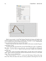
Extend a line from both sides down to the corners of the canvas to make fill appear
at the bottom. Great.
Go ahead and add a few more lines on top of the filled area to give it a mountainlike look. If brown ducks are on your way, you can hide them by clicking the
"Toggle vertex ducks" button at the top of canvas window (the second one
from the left).
Draw tool is great for drawing complex shapes, but you end up with a bunch of
ducks, which are hard to manipulate with the Transform Tool in the way we described
above. There are two solutions here.
First, you can increase "Smooth" value in the Tool Options Dialog while using
Draw Tool. That will reduce the count of vertices produced at drawing time, but will
2.4. CREATING SHAPES
27
make your shape less detailed.
Second, you can use Smooth Move Tool to deform existing shape. Go for it and
click Smooth Move Tool button in the toolbox. The trick about this tool is that it
affects selected ducks only. Press and hold your left mouse button at the empty place
28
CHAPTER 2. DIVING IN
Warning!
Don’t use Alt 2 shortcut to turn off visibility of vertex ducks while you
using Draw Tool. There’s a bug that will cause Synfig Studio to hang.
of the canvas. Drag to create selection box. Release mouse button when you are done.
Or just hit Ctrl A to select all ducks. Now you can deform selected segments of
BLines. You can change size of influence area by tweaking "Radius" at the Tool
Options Panel.
What about outline width? There is a Width Tool for that purpose. It is designed
for increasing or decreasing the width of a line much like you would with a pencil
on paper. Click Width Tool button on the toolbox, move your stylus over the line
you want to change, press and move cursor back and forth along the line, like you
scratching something. The width of outline will be increased at the places where you
moved the cursor. If you want to decrease the width, just hold "Ctrl" while scratching.
Easy!
If you don’t want Width Ducks to be displayed, during usage of the Width Tool,
just turn them off by pressing "Toggle width ducks" button at the top of canvas window.
Warning!
Don’t use Alt 5 shortcut to turn off visibility of width ducks while you
using Width Tool. There’s a bug that will cause Synfig Studio to hang.
2.4.5
Other ways to create BLines
Is that all? Not yet. You can use Circle, Rectangle, Star and Polygon tools to
create BLines too. Just check the "Create Outline BLine" and "Create
Region BLine" options at Tool Options Panel when using those tools.
Creating geometric primitive as BLine gives you a better control over it’s shape
and look. For example, if you want a deformed star, then you can use Star Tool to
create it as outline and region BLines and then use Transform Tool to deform it.
Now you are ready for the last tutorial in this section. Hang on!
2.5. ANIMATING SHAPES
2.5
2.5.1
29
Animating Shapes
Basic settings
In this tutorial we will learn how to create a simple animation of a growing flower
using blines.
Start Synfig Studio — a new animation will be created.
If you already have Synfig Studio started, select "File"
→ "New" in the toolbox.
First, we need to create a gradient for a background.
Click on the outline and fill colors in the toolbox to select a
colors our gradient will have. You can also directly edit the
gradient by clicking the gradient line in the toolbox.
Select the Gradient Tool and drag your cursor vertically
across the canvas to fill it with the gradient.
Next, select the Bline Tool and in the Tool Options Panel, make sure that only
"Create Regiion BLine" is checked. In the toolbox, set the fill color to green.
Draw a kind of triangle with the Bline tool. To close the shape after drawing the 3
vertices, right click on the first vertex and choose "Loop Bline".
Now that the shape is closed, you can "create" the bline shape by selecting another
tool or pressing a button with gear-like icon at the bottom of the Tool Options Panel.
This will be the base of the stem. You can tweak the tangent handles (red dots) a
bit to make a rounder triangle. With the Transform Tool, right-click on each vertex and
select "Split Tangents", so the tangent handles of each vertex can be moved
separately. We’re done with the basic settings.
30
2.5.2
CHAPTER 2. DIVING IN
Animate the stem
In the Canvas Menu, select "Edit" → "Properties". Go to the Time tab, set
the "End time" to "6s" and click OK button.
Click at the beginning of the timetrack ("0f"), then, on the Keyframes Panel (the
one with a key icon) click button with a "+" icon (add a new keyframe). Keyframes
allow us to settle down the scene; i.e. on a keyframe, every element of the scene will
have all its properties remembered. Click again on the timetrack, at "4.5s". Press
the green circle at the bottom right of the canvas (or whatever icon you have there,
depending on your icon theme) to switch to the Animate Editing Mode (the circle is
now red).
With the Transform Tool, select the green sprout, and move the upper vertex up
to make a stem. You can play with the vertex handles to bend the shape a bit if you
want.
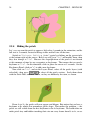
While you are still at "4.5s", right-click on the stem border, close to the top, and
choose "Insert Item (smart)". Do the same on the other side of the stem.
Right click on those new points and choose "Split Tangents" again. Then try
2.5. ANIMATING SHAPES
31
to make a shape that looks like the one on the image, to create the flower bud.
Now if you click on "2s" (for example), you’ll see that the shape of the bud
is slightly visible, even if the sprout is rather small, and even if the bud ducks are
invisible.
Let’s say we want the bud to appear only at 3.5s, and be full size at 4.5s.
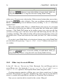
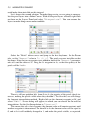
Click on "3.5s" on the timetrack. Now take a look at the "Params" and
"Timetrack" panels at the bottom. You’ll see that each parameter in the Params
Panel matches a row in the Timetrack Panel. The last parameter is the vertices list.
Click on the small arrow on the left to unfold the list. You should see something like
this:
Each big green dot (or waypoint) stands for a recorded value (here the vertices positions were recorded at 0f with the keyframe, and at 4s when we moved some vertices
32
CHAPTER 2. DIVING IN
or vertices handles). The two vertices we added to make the bud are marked at "DYN"
(dynamic). Right-click on them in the params list, and select "Mark Activepoint as
Off".
The panel should now look like this, the grayed part being the part where the bud
vertices have no effect on the stem.
For example if you click on "2s" or even "3s" now, the bud shape is not visible.
It starts to appear only a little after 3.5s.
However, the shape of the stem may not look very nice during its growth between
0 and 4s. Make sure you’re still in Animate Edit Mode, and tweak the shape at various
moments in time, to get something you like.
The animation of the stem is now finished, but it still lacks the petals. You can
watch a preview of your animation: Go to "File" → "Preview", validate, wait
for the preview to be generated, and watch.
Note
Previews are often pixelated and blurry, but the final render will be clean-cut.
Higher quality previews are obtainable by using higher values for ’Zoom’
and ’Frames per second’ in the preview dialog window.
2.5.3
Adding the petals
Now leave the "Animate Editing Mode" by clicking on the red circle at the
right bottom of the canvas.
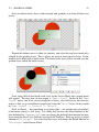
Change the fill color to pink, and create a petal with the BLine Tool. You’ll notice
that the green duck that allows easy movement of a shape is at the center of the canvas.
Select all the vertices of the petal with Ctrl A and move them close to the green
duck (with the Transform Tool), as shown.
Then drag the green duck very close to the top of the bud. Hit Ctrl A again to
select all vertices of the petal and tweak it a bit with Rotate Tool. Also, in the Layers
Panel select the petal layer and put it under the stem layer. Click on the petal to select
it, then ctrl-click on the stem. Both objects should be selected.
2.5. ANIMATING SHAPES
33
Now click on the vertex at the top of the stem and ctrl-click on the green duck of
the petal (both should appear in a lighter color, as they are selected). Then right-click
on the stem top vertex, and select "Link". The petal will move a bit as the green
duck is snapped on the stem vertex.
Now that there’s a link between the petal and the top of the stem, when the top of
the stem moves, the petal will follow the move. (And if the green duck of the petal
move, the top of the stem will move, but we don’t want to do that here.)
On the Layers Panel, select the newly created Petal layer and duplicate it (with the
third button, on the bottom of the panel). On the canvas, press Ctrl A to select all
the vertices of the duplicated petal, and move them a little, so the petals are no longer
overlaid. (Don’t move the green duck, just the orange ones). Repeat the process
several time, to get something looking like this image.
Note that the duplicated petals are also linked to the stem. If you go back to the
first keyframe, you’ll see that the petals are visible. We don’t want that. We want the
petals to appear and bloom almost at the end of the growth.
34
2.5.4
CHAPTER 2. DIVING IN
Hiding the petals
Let’s say we want the petals to appear a little after 4 seconds in the animation, and be
full size at 5 seconds, instead of being visible and full size all the time.
Switch to "Animate Editing Mode" again by clicking on the green circle
at the bottom right of the canvas. But if we will go to "4s" and modify them, then
they also change at "5s". Because the shape/position of the petals is not fixated
at this moment of time by any waypoints or keyframes. That means that we need a
keyframe at "5s". On the timetrack, click to place the cursor at 5 seconds. On the
Keyframes Panel, click on "+" to add a new keyframe.
Now click on "4s", and on the Layers Panel, select all the petals layers (with
ctrl+click), then press Ctrl A to select all the petals vertices. Scale them down
with the Scale Tool, and move them, so they are hidden by the stem, as shown.
From 4s to 5s, the petals will now appear and bloom. But notice that we have a
keyframe at 0s which also remembers petals shape. That makes the problem — the
petals are still visible from the first keyframe to the 4s keyframe. We could either an
make petals tiny and hidden tweaking their size on every frame from 0s to 4s, or we
2.5. ANIMATING SHAPES
35
could make them invisible on this interval.
Let’s choose the second solution. To make things easier, we are going to encapsulate the petal layers into a Inline Canvas. With all the petal layers selected, right-click
on them on the Layers Panel and select "Encapsulate". You can rename the
layers to make things more understandable.
Select the "Petals" inline canvas and jump to the first keyframe. In the Param
tabs, set the "Amount" value to "{{{1}}}". The petals are now invisible on that
keyframe. Note that two waypoints were added in front of the "Amount" parameter,
one at 0s and the other at 5s. Drag the 5s waypoint to 4s, so that the opacity of the
petals will be 1 at 4s.
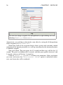
There is still one problem left: from 0s to 4s, the opacity of the petals slowly increases, making the petals visible when they shouldn’t. To solve this, we will change
the Amount interpolation method. Right click on the Amount waypoint at 0f, and
select "Edit". A new dialog will appear, in which you can choose the In and Out
interpolation. Set the Out Interpolation to "Constant".
This means that after that waypoint, the Amount value will remain constant, until
another waypoint is encountered. So from 0f to 4s the Amount value will be equal to
0, and at 4s it will suddenly changed to 1, and make the petals visible, as expected.
36
CHAPTER 2. DIVING IN
Tip
You can also change waypoint Out interpolation by right-clicking on it and
selecting "Out" → "Constant".
Alternatively, we could have achieved the same effect by setting the In Interpolation
of the waypoint at 4s to "Constant".
Notice how (half of) the waypoint changes from a green circle (meaning smooth
animation of the amount parameter) to a red step (meaning that the amount parameter
is suddenly stepped).
Now you’re done. The stem grows for 4.5 seconds and then stays still the last 1.5
second. The petals are hidden until 4 seconds, and then grow quickly between 4 and
5 seconds, and stay still the last 1 second too.
Click on "File" → "Render" to render your animation. Select any format
you want, and ensure that "Use current frame" option is unchecked (otherwise, one frame only will be rendered).