1
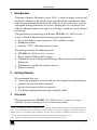
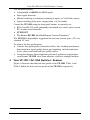
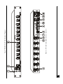
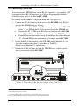
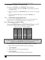
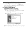
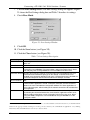
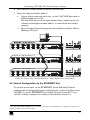
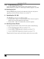
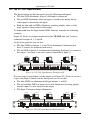
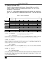
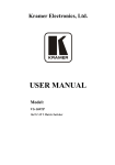
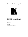
Connecting a VP-1201 12x1 XGA Switcher / Scanner
6. Press the BUS TERM button on the first and last units.
7. Insert the highest machine address1:
On one of the connected units only, set the CASCADE dipswitch to
OFF and then back to ON.
The blue LED on one of the input buttons blinks (indicating the last
selection of the highest machine address, as stored in the non-volatile
memory)
Press the input button denoting the current highest machine address.
Blinking will cease
OFF
ON
1
2
3
4
5
6
7
8
1
2
3
4
5
6
7
8
1
2
3
4
5
6
7
8
1
2
3
4
5
6
7
8
1
2
3
4
5
6
7
8
1
2
3
4
5
6
7
8
Machine # = 1; Machine Address = 2
OFF
ON
Machine # = 1; Machine Address = 3
OFF
ON
Figure 26: Connecting VP-1201 Machines – Input Expansion Configuration
5.6 Control Configuration via the ETHERNET Port
To control several units via the ETHERNET (in the Individual Control
configuration or the Input Expansion configuration), connect the Master unit
(MACH # 1) via the ETHERNET port to the LAN port of your PC. Using
your PC, initially configure the settings as described in section 5.4.
1 The highest MACHINE ADDRESS is the total number of machines in the Input Expansion configuration. In Figure 26, for
example, the highest machine address will be 3
27