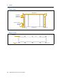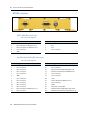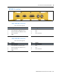
1
USER GUIDE Trimble® BX960 GNSS Receiver Enclosure NORTH AMERICA Trimble Engineering & Construction Group 5475 Kellenburger Road Dayton, Ohio 45424-1099 • USA 800-538-7800 (Toll Free) +1-937-245-5154 Phone +1-937-233-9441 Fax EUROPE Trimble GmbH Am Prime Parc 11 65479 Raunheim • GERMANY +49-6142-2100-0 Phone +49-6142-2100-550 Fax ASIA-PACIFIC Trimble Navigation Singapore Pty Limited 80 Marine Parade Road #22-06, Parkway Parade Singapore 449269 • SINGAPORE +65-6348-2212 Phone +65-6348-2232 Fax www.trimble.com USER GUIDE Trimble BX960 GNSS Receiver Enclosure ® Revision A April 2009 F Corporate Office Trimble Navigation Limited 935 Stewart Drive Sunnyvale, CA 94085 USA www.trimble.com E-mail: [email protected] Legal Notices © 2008, Trimble Navigation Limited. All rights reserved. Trimble, and the Globe & Triangle logo are trademarks of Trimble Navigation Limited, registered in the United States and in other countries. CMR+, Maxwell, and Zephyr are trademarks of Trimble Navigation Limited. Microsoft, Windows, and Windows NT are either registered trademarks or trademarks of Microsoft Corporation in the United States and/or other countries. All other trademarks are the property of their respective owners. Release Notice This is the April 2009 release (Revision A) of the BX960 GNSS Receiver Enclosure User Guide. Product Limited Warranty Information For applicable product Limited Warranty information, please refer to the Limited Warranty Card included with this Trimble product, or consult your local Trimble authorized dealer. Notices Class B Statement – Notice to Users. This equipment has been tested and found to comply with the limits for a Class B digital device, pursuant to Part 15 of the FCC rules and Part 90. These limits are designed to provide reasonable protection against harmful interference in a residential installation. This equipment generates, uses, and can radiate radio frequency energy and, if not installed and used in accordance with the instructions, may cause harmful interference to radio communication. However, there is no guarantee that interference will not occur in a particular installation. If this equipment does cause harmful interference to radio or television reception, which can be determined by turning the equipment off and on, the user is encouraged to try to correct the interference by one or more of the following measures: – Reorient or relocate the receiving antenna. – Increase the separation between the equipment and the receiver. – Connect the equipment into an outlet on a circuit different from that to which the receiver is connected. – Consult the dealer or an experienced radio/TV technician for help. Changes and modifications not expressly approved by the manufacturer or registrant of this equipment can void your authority to operate this equipment under Federal Communications Commission rules. Canada This Class B digital apparatus complies with Canadian ICES-003. Cet appareil numérique de la classe B est conforme à la norme NMB-003 du Canada. This apparatus complies with Canadian RSS-GEN, RSS-310, RSS-210, and RSS-119. Cet appareil est conforme à la norme CNR-GEN, CNR-310, CNR-210, et CNR-119 du Canada. Europe This product (the BX960 GNSS Receiver Enclosure) is intended to be used in all EU member countries, Norway, and Switzerland. This product has been tested and found to comply with the requirements for a Class B device pursuant to European Council Directive 89/336/EEC on EMC, thereby satisfying the requirements for CE Marking and sale within the European Economic Area (EEA). 2 BX960 GNSS Receiver Enclosure User Guide Notice to Our European Union Customers Directive 1999/5/EC Hereby, Trimble Navigation, declares that the BX960 GNSS receiver enclosure is in compliance with the essential requirements and other relevant provisions of Directive 1999/5/EC. Waste Electrical and Electronic Equipment (WEEE) For product recycling instructions and more information, please go to www.trimble.com/ev.shtml. Recycling in Europe: To recycle Trimble WEEE (Waste Electrical and Electronic Equipment, products that run on electrical power.), Call +31 497 53 24 30, and ask for the “WEEE Associate”. Or, mail a request for recycling instructions to: Trimble Europe BV c/o Menlo Worldwide Logistics Meerheide 45 5521 DZ Eersel, NL Declaration of Conformity We, Trimble Navigation Limited, 935 Stewart Drive PO Box 3642 Sunnyvale, CA 94088-3642 United States +1-408-481-8000 declare under sole responsibility that the product: BX960 GNSS Receiver Enclosure complies with Part 15 of FCC Rules. Operation is subject to the following two conditions: (1) this device may not cause harmful interference, and (2) this device must accept any interference received, including interference that may cause undesired operation. Contents 1 Introduction . . . . . . . . . . . . . . . . . . . . . . . . . . . . . . . . . . . . 5 About the BX960 receiver . Related information . . . . Technical Support. . . . . . Your comments . . . . . . . 2 . . . . . . . . . . . . . . . . . . . . . . . . . . . . . . . . . . . . . . . . . . . . . . . . . . . . . . . . . . . . . . . . . . . . . . . . . . . . . . . . . . . . . . . . . . . . . . . . . . . . . . . . . . . . . . . . . . . . . . . . . . . . . . . . . . . . . . . . . . . . . . . . . . . . . . . . . . . . . . . . . . . . . . . . . . . . . . . . . . . . . . . . . . . . . . . . . . . . . . . . . . . . . . . . . . . . . . . . . . . . . . . . . . . . . . . . . . . . . . . . . . . . . . . . . . . . . . . . . . . . . . . . . . . . . . . . . . . . . . . . . . . . . . . . . . . . . . . . . . . . . . . . . . . . . . . . . . . . . . . . . . . . . . . . . . . . . . . . . . . . . . . . . . . . . . . . . . . . . . . . . . . . . . . . . . . . . . . . . . . . . . . . . . . . . . . . . . . . . . . . . . . . . . . . . . . . . . . . . . . . . . . . . . . . . . . . . . . . . . . . . . . . . . . . . . . . . . . . . . . . . . . . . . . . . . . . . . . . . . . . . . . . . . . . . . . . . . . . . . . . . . . . . . . . . . . . . . . . . . . . . . . . . . . . . . . . . . . . . . . . . . . . . . . . . . . . . . . . . . . . . . . . . . . . . . . . . . . . . . . . . . . . . . . . 6 6 6 6 . . . . . . . . . . . . . . . . . . . . . . . . . . . . . . . . . . . . . . . . . . . . . . . . . . . . . . . . . . . . . . . . . . . . . . . . . . . . . . . . . . . . . . . . . . . . . . . . . 8 . 8 . 8 . 8 . 9 10 10 10 . . . . . . . . . . . . . . . . . . . . . . . . . . . . . . . . . . . . . . . . . . . . . . . . . . . . . . . . . . . . . . . . . . . . . . . . . . . . . . . . . . . . . . . . . . . . . . . . . . . . . . . . . . . . . . . . . . . . . . . . 12 12 12 12 12 12 13 13 14 14 . . . . . . . . . . . . . . . . . . . . . . . . . . . . . . . . . . . . . . . . . . . . . . . . . . . . . . . . . . . . . . . . . . . . . . . . 16 16 16 17 17 17 Specifications. . . . . . . . . . . . . . . . . . . . . . . . . . . . . . . . . . . 19 Physical specifications . . . . . . Performance specifications . . . Electrical specifications . . . . . Communication specifications A . . . . Configuring the BX960 Receiver . . . . . . . . . . . . . . . . . . . . . . . . 15 BX960 receiver I/O . . . . . . . . . . . . . . . . . . . . . . . . . . . . . . . . . . . . BX960-2 receiver I/O . . . . . . . . . . . . . . . . . . . . . . . . . . . . . . . . . . . Configuring the BX960 receiver to output reference station data . . . . . . . Configuring the BX960 or BX960-2 receiver to output rover RTK positions. Configuring the BX960-2 receiver to output heading data . . . . . . . . . . . For more information . . . . . . . . . . . . . . . . . . . . . . . . . . . . . . . . . . 5 . . . . Installation . . . . . . . . . . . . . . . . . . . . . . . . . . . . . . . . . . . . 11 Unpacking and inspecting the shipment . . . . Shipment carton contents . . . . . . . . . Reporting shipping problems . . . . . . . Supported antennas . . . . . . . . . . . . . . . . . Installation guidelines . . . . . . . . . . . . . . . . Considering environmental conditions . Mounting the antennas . . . . . . . . . . . . . . . Sources of electrical interference . . . . . Connections . . . . . . . . . . . . . . . . . . . . . . Routing and connecting the antenna cable. . . 4 . . . . Features and Functions . . . . . . . . . . . . . . . . . . . . . . . . . . . . . . 7 Receiver architecture. . . . BX960 . . . . . . . . . BX960-2 . . . . . . . . BX960 receiver features . . BX960-2 receiver features . Use and care . . . . . . . . . Radio and radar signals . . COCOM limits . . . . . . . . 3 . . . . . . . . . . . . . . . . . . . . . . . . . . . . . . . . . . . . . . . . . . . . . . . . . . . . . . . . . . . . . . . . . . . . . . . . . . . . . . . . . . . . . . . . . . . . . . . . . . . . . . . . . . . . . . . . . . . . . . . . . . . . . . . . . . . . . . . . . . . . . . . . . . . . . . . . . . . . . . . . . . . . 20 20 21 21 Upgrading the Receiver Firmware . . . . . . . . . . . . . . . . . . . . . . . 23 The WinFlash utility . . . . . . . . . . . . . . . . . . . . . . . . . . . . . . . . . . . . . . . . . . . . . . . 24 BD960 GNSS Receiver Module User Guide 3 Installing the WinFlash utility . . . . . . . . . . . . . . . . . . . . . . . . . . . . . . . . . . . . . 24 Upgrading the receiver firmware . . . . . . . . . . . . . . . . . . . . . . . . . . . . . . . . . . . . . . . 25 B Troubleshooting . . . . . . . . . . . . . . . . . . . . . . . . . . . . . . . . . 27 Receiver issues. . . . . . . . . . . . . . . . . . . . . . . . . . . . . . . . . . . . . . . . . . . . . . . . . . . 28 C Drawings . . . . . . . . . . . . . . . . . . . . . . . . . . . . . . . . . . . . . 29 Plan view . . . . . . . . . . . . . . . . . . . . . . . . . . . . . . . . . . . . . . . . . . . . . . . . . . . . . . 30 Edge view . . . . . . . . . . . . . . . . . . . . . . . . . . . . . . . . . . . . . . . . . . . . . . . . . . . . . . 30 D Receiver Connector Pinout Information. . . . . . . . . . . . . . . . . . . . 31 BX960 receiver . . . . . . . . . . . . . . . . . GPS1 DE9 (M) connector . . . . . . Data/Power DA26 (M) connector BX960-2 receiver. . . . . . . . . . . . . . . . GPS1 DE9 (M) connector . . . . . . GPS2 DE9 (M) connector . . . . . . Data/Power DA26 (M) connector Master Port 3 TX line . . . . . . . . . . . . . . . . . . . . . . . . . . . . . . . . . . . . . . . . . . . . . . . . . . . . . . . . . . . . . . . . . . . . . . . . . . . . . . . . . . . . . . . . . . . . . . . . . . . . . . . . . . . . . . . . . . . . . . . . . . . . . . . . . . . . . . . . . . . . . . . . . . . . . . . . . . . . . . . . . . . . . . . . . . . . . . . . . . . . . . . . . . . . . . . . . . . . . . . . . . . . . . . . . . . . . . . . . . . . . . . . . . . . . . . . . . . . . . . . . . . . . . . . . . . . . . . . . . . . . . . . . . . . . . . . . . . . . . . . 32 32 32 33 33 33 34 34 Glossary . . . . . . . . . . . . . . . . . . . . . . . . . . . . . . . . . . . . . . 35 4 BD960 GNSS Receiver Module User Guide CHAPTER 1 Introduction About the BX960 receiver Related information Technical Support Your comments 1 Welcome to the BX960 GNSS Receiver Enclosure User Guide. This manual describes how to set up and use the Trimble® BX960 receiver enclosure. The BX960 GNSS receiver enclosure is a rugged housing that holds one or two BD960 GNSS receiver modules. The receiver enclosure uses advanced navigation architecture to achieve real-time centimeter accuracies with minimal latencies. Use this manual in conjunction with the BD960 GNSS Receiver User Guide: All firmware features and software configuration utilities are documented in that manual. Even if you have used other Global Positioning System (GPS) products before, Trimble recommends that you spend some time reading this manual to learn about the special features of this product. If you are not familiar with GPS, visit the Trimble website (www.trimble.com) for an interactive look at Trimble and GPS. BX960 GNSS Receiver Enclosure User Guide 5 1 Introduction About the BX960 receiver The BX960 receiver enclosure allows OEM and system integrator customers to rapidly integrate high accuracy GNSS into their applications. The single-board BX960 is ideal as either a base station or a rover. The two-board model (the BX960-2) is suited for applications that require precise heading in addition to positions. The BX960 receiver provides reliable operation in all environments, and a positioning interface to an office computer, external processing device, or control system. You can control the receiver through a serial or Ethernet port using binary interface commands or web GUI. Both receivers are packaged with an AC-to-DC power supply and a DB26-to-DB9/RJ45/power cable. Related information The web browser interface includes help screens to assist you to quickly find the information you need. Technical Support If you have a problem and cannot find the information you need in the product documentation, contact your local dealer. Alternatively, go to the Support area of the Trimble website (www.trimble.com/support.shtml) and then select the product that you need information on. Product updates, documentation, and any support issues are available for download. If you need to contact Trimble technical support, complete the online inquiry form at www.trimble.com/support_form.asp. Your comments Your feedback about the supporting documentation helps us to improve it with each revision. Email your comments to [email protected]. 6 BX960 GNSS Receiver Enclosure User Guide CHAPTER 2 Features and Functions 2 In this chapter: Receiver architecture BX960 receiver features BX960-2 receiver features Use and care Radio and radar signals COCOM limits BX960 GNSS Receiver Enclosure User Guide 7 2 Features and Functions Receiver architecture BX960 The BX960 receiver provides an enclosure for a single BD960 GNSS receiver. Simply connect power and an antenna to create a complete GNSS system. Three LEDs indicate power, differential corrections, and satellite tracking status. Access to serial, Ethernet, and 1PPS is available through DB connectors. BX960-2 When computing offsets from the antenna to the point of interest, or providing consistent vehicle orientation, heading information is critical. The BX960-2 receiver enclosure contains two BD960 GNSS receivers, and so can provide that heading information. The technique of Moving Base RTK provides an accurate vector between the two boards. CMR corrections from the master to slave board are routed inside the receiver on a serial port. The Moving Base RTK vector outputs can be sent in ASCII or binary format through the slave board DB9 serial port. An additional DB9 connector, antenna connector, and three more LEDs are installed on the BX960-2 enclosure. BX960 receiver features The BX960 receiver provides the following features: • 72-channel L1/L2/L2C/L5 GPS plus L1/L2 GLONASS receiver • OmniSTAR XP/HP/VBS service capable • SBAS (Satellite Based Augmentation System) compatible: • 8 – WAAS (Wide Area Augmentation System) – EGNOS (European Geo-Stationary Navigation System) – MSAS (MTSAT Satellite-Based Augmentation System) Configuration and monitoring through the following methods: – Web interface – Networked or peer-to-peer Ethernet – Binary interface commands • Choice of external GPS antenna for base station or rover operation • –40 °C to +67 °C (–40 °F to +149 °F) operating temperature range • 9 V to 28 V DC input power range, with over-voltage protection • Moving baseline capability BX960 GNSS Receiver Enclosure User Guide Features and Functions • 5 Hz, 10 Hz, or 20 Hz measurement update rate • RoHS compliant • 1 pulse per second (1PPS) output • 3 LEDs that indicate power, satellite tracking, and differential data • DB9, DB26, and TNC antenna connectors • Rugged 4-hole mounting aluminium housing 2 BX960-2 receiver features The BX960-2 receiver provides the following features: • Two 72-channel L1/L2/L2C/L5 GPS plus L1/L2 GLONASS receivers • OmniSTAR XP/HP/VBS service capable • SBAS compatible: • – WAAS – EGNOS – MSAS Configuration and monitoring through the following methods: – Web interface – Networked or peer-to-peer Ethernet – Binary interface commands • Choice of external GPS antenna for base station or rover operation • –40 °C to +67 °C (–40 °F to +149 °F) operating temperature range • 9 V to 28 V DC input power range, with over-voltage protection • Moving baseline capability • 5 Hz, 10 Hz, or 20 Hz measurement update rate • RoHS compliant • 1 pulse per second (1PPS) output • 6 LEDs that indicate power, satellite tracking, and differential data • 2 x DB9, DB26, and 2 x TNC antenna connectors • Rugged 4-hole mounting aluminium housing BX960 GNSS Receiver Enclosure User Guide 9 2 Features and Functions Use and care C CAUTION – Operating or storing the receiver outside the specified temperature range can damage it. For more information, see Chapter 5, Specifications. Always mount the BD960 receiver in a suitable casing. Radio and radar signals High-power signals from a nearby radio or radar transmitter can overwhelm the BD960 receiver circuits. This does not harm the instrument, but it can prevent the receiver electronics from functioning correctly. Avoid using the receiver within 400 m of powerful radar, television, or other transmitters. Low-power transmitters such as those used in portable phones and walkie-talkies normally do not interfere with the operation of the receivers. COCOM limits The U.S. Department of Commerce requires that all exportable GPS products contain performance limitations so that they cannot be used in a manner that could threaten the security of the United States. The following limitations are implemented on this product: • 10 Immediate access to satellite measurements and navigation results is disabled when the receiver velocity is computed to be greater than 1,000 knots, or its altitude is computed to be above 18,000 meters. The receiver GPS subsystem resets until the COCOM situation clears. As a result, all logging and stream configurations stop until the GPS subsystem is cleared. BX960 GNSS Receiver Enclosure User Guide CHAPTER 3 Installation In this chapter: Unpacking and inspecting the shipment Supported antennas Installation guidelines Mounting the antennas Connections Routing and connecting the antenna cable 3 Trimble recommends that you read this section before you install the BX960 receiver. BX960 GNSS Receiver Enclosure User Guide 11 3 Installation Unpacking and inspecting the shipment Visually inspect the shipping cartons for any signs of damage or mishandling before unpacking the receiver. Immediately report any damage to the shipping carrier. Shipment carton contents The shipment will include one or more cartons. This depends on the number of optional accessories ordered. Open the shipping cartons and make sure that all of the components indicated on the bill of lading are present. Reporting shipping problems Report any problems discovered after you unpack the shipping cartons to both Trimble Customer Support and the shipping carrier. Supported antennas The BD960 receiver tracks six different GNSS frequencies: The Trimble Zephyr™ II antenna supports all these frequencies. Other antennas may be used. However, ensure that the antenna you choose supports the frequencies you need to track and operates at either 3.3 V or 7.1 V with a greater than 40 dB signal at the board antenna port. Installation guidelines The BX960 receiver is designed to be mounted on a flat surface in any orientation. The bottom of the receiver features mounting flanges and four slotted holes for securing to a flat surface. Considering environmental conditions Install the BX960 receiver in a location situated in a dry environment. Avoid exposure to extreme environmental conditions. This includes: • Water or excessive moisture • Excessive heat greater than 75 °C (167 °F) • Excessive cold less than –40 °C (–38 °F) • Corrosive fluids and gases Avoiding these conditions improves the BX960 receiver’s performance and long-term product reliability. 12 BX960 GNSS Receiver Enclosure User Guide Installation 3 Mounting the antennas Choosing the correct location for the antenna is critical to the installation. Poor or incorrect placement of the antenna can influence accuracy and reliability and may result in damage during normal operation. Follow these guidelines to select the antenna location: • If the application is mobile, place the antenna on a flat surface along the centerline of the vehicle. • Choose an area with clear view to the sky above metallic objects. • Avoid areas with high vibration, excessive heat, electrical interference, and strong magnetic fields. • Avoid mounting the antenna close to stays, electrical cables, metal masts, and other antennas. • Avoid mounting the antenna near transmitting antennas, radar arrays, or satellite communication equipment. Sources of electrical interference Avoid the following sources of electrical and magnetic noise: • gasoline engines (spark plugs) • television and computer monitors • alternators and generators • electric motors • propeller shafts • equipment with DC-to-AC converters • fluorescent lights • switching power supplies BX960 GNSS Receiver Enclosure User Guide 13 3 Installation Connections The following figure shows a typical setup for the BX960-2 receiver. Zephyr antennas BX960-2 receiver enclosure Power The computer connection provides a means to set up and configure the receiver. Routing and connecting the antenna cable Mount the antenna and then route the antenna cable from the GPS antenna to the receiver, as shown above. Avoid the following hazards when routing the antenna cable: • Sharp ends or kinks in the cable • Hot surfaces (such as exhaust manifolds or stacks) • Rotating or reciprocating equipment • Sharp or abrasive surfaces • Door and window jams • Corrosive fluids or gases After routing the cable, connect it to the BX960 receiver. Use tie-wraps to secure the cable at several points along the route. For example, to provide strain relief for the antenna cable connection use a tie-wrap to secure the cable near the base of the antenna. Note – When securing the cable, start at the antenna and work towards the BX960 receiver. When the cable is secured, coil any slack. Secure the coil with a tie-wrap and tuck it in a safe place. 14 BX960 GNSS Receiver Enclosure User Guide CHAPTER 4 Configuring the BX960 Receiver In this chapter: BX960 receiver I/O BX960-2 receiver I/O Configuring the BX960 receiver to output reference station data Configuring the BX960 or BX960-2 receiver to output rover RTK positions Configuring the BX960-2 receiver to output heading data 4 This chapter describes how to configure the BX960 and BX960-2 receivers. BX960 GNSS Receiver Enclosure User Guide 15 4 Configuring the BX960 Receiver The connectors support the following I/O. For more information, see Receiver Connector Pinout Information, page 31. BX960 receiver I/O Serial port 1 Ethernet DB26 connector labeled Data/Power 1PPS Serial Port 2 DB9 connector labeled GPS1 BX960-2 receiver I/O Serial port 1 (for the master) Ethernet (for the master) DB26 connector labeled Data/Power 1PPS Serial Port 2 (for the master) DB9 connector labeled GPS1 Serial Port 2 (for the slave) DB9 connector labeled GPS2 Note – Both master and slave boards are shipped from the factory with their default settings. In this mode, there is no communication between the two boards. Configuring the BX960 receiver to output reference station data 1. Connect your computer to the DB9 port labeled GPS1 or use the provided adapter cable to connect to the DB26 port labeled Data/Power. 2. Do one of the following: 3. 16 – Enter a base station position using known coordinates (MSController, Configuration Toolbox, or Web GUI software). – Select a Here position (MSController or Web GUI software only). Use the MSController, Configuration Toolbox, or Web GUI software to enable CMR or RTCM outputs from serial port 1 or 2. BX960 GNSS Receiver Enclosure User Guide Configuring the BX960 Receiver 4 Configuring the BX960 or BX960-2 receiver to output rover RTK positions 1. Supply differential data to either the DB9 port labeled GPS1 or the DB26 port labeled Data/Power. 2. If there is an antenna attached, the differential data (middle) LED on receiver 1 lights up. This shows that you are receiving valid differential data. It does not show that you are computing a fixed solution. 3. Connect your computer to the DB9 port labeled GPS1 or use the provided cable to connect to the DB26 port labeled Data/Power. 4. Use the MSController or Web GUI software to make sure that you are computing fixed solutions. 5. Use the MSController, Configuration Toolbox, or Web GUI software to enable the required ASCII (NMEA) or Binary (Data Collector Format Report Packets) massages from serial port 1 or 2. Configuring the BX960-2 receiver to output heading data 1. Connect your computer to the DB9 port labeled GPS1 or use the provided adapter cable to connect to the DB26 port labeled Data/Power. 2. Use the MSController, Configuration Toolbox, or Web GUI software to enable CMR+™ outputs at 10 Hz on port 3. 3. If there is an antenna attached, the differential data (middle) LED on receiver 2 lights up. 4. Connect your computer to the DB9 port labeled GPS2. 5. Use the MSController or Configuration Toolbox software to enable either ASCII messages (NMEA AVR or VHD) or Binary (Report Packet 40h, Type 27 record) messages from serial port 2. For more information For more advanced information on how to configure the receivers inside the BX960 receiver enclosure, refer to the BD960 GNSS Receiver User Guide. BX960 GNSS Receiver Enclosure User Guide 17 4 18 Configuring the BX960 Receiver BX960 GNSS Receiver Enclosure User Guide CHAPTER 5 Specifications In this chapter: Physical specifications Performance specifications Electrical specifications Communication specifications 5 This chapter details the specifications for the receiver enclosure. Specifications are subject to change without notice. BX960 GNSS Receiver Enclosure User Guide 19 5 Specifications Physical specifications Feature Specification Dimensions (L x W x H) 261 mm x 140 mm x 55 mm Temperature Operating Storage –40 °C to +67 °C (–40 °F to +152 °F) –55 °C to +85 °C (–40 °F to +176 °F) Vibration MIL810F, tailored Random 6.2 gRMS operating Random 8 gRMS survival Mechanical shock MIL810D ±40 g operating ±75 g survival I/O Connector D-sub DE9 and DA26 (The BX960-2 receiver has an additional DE9 connector.) Antenna Connector TNC (The BX960-2 receiver has an additional TNC connector.) Performance specifications Feature Specification Measurements • • • • • • • Advanced Trimble Maxwell™ Custom Survey GNSS technology High-precision multiple correlator for GNSS pseudorange measurements Unfiltered, unsmoothed pseudorange measurements data for low noise, low multipath error, low time domain correlation and high dynamic response Very low receiver noise GNSS carrier phase measurements with <1 mm precision in a 1 Hz bandwidth Signal-to-Noise ratios reported in dBHz 72 Channels: - GPS L1 C/A Code, L2C, L1/L2/L51 Full Cycle Carrier - GLONASS L1 C/A Code, L1 P Code,L2 C/A2, L2 P Code, - 4 additional channels for SBAS WAAS, EGNOS, and MSAS support - L-Band OmniSTAR VBS,HP, and XP The BX960-2 receiver contains an additional 72-channel receiver that is configured for heading only. Code differential GPS positioning1 3D Typically, <1 m SBAS (WAAS/EGNOS/MSAS) Typically <1 m Horizontal accuracy2 Typically <5 m Vertical accuracy2 OmniSTAR positioning VBS service accuracy XP service accuracy HP service accuracy 20 Horizontal <1 m Horizontal 20 cm, Vertical 30 cm Horizontal 10 cm, Vertical 15 cm BX960 GNSS Receiver Enclosure User Guide Specifications Feature Specification RTK positioning Horizontal accuracy Vertical accuracy ±(10 mm + 1 ppm) RMS ±(20 mm + 1 ppm) RMS Initialization time Initialization reliability3 Typically, 10 seconds Typically >99.9% 5 1 Accuracy and reliability may be subject to anomalies such as multipath, obstructions, satellite geometry, and atmospheric conditions. Always follow recommended practices. 2 Depends on WAAS, EGNOS, and MSAS system performance. 3 May be affected by atmospheric conditions, signal multipath, and satellite geometry. Initialization reliability is continuously monitored to ensure highest quality. Electrical specifications Feature Specification Power 9 V to 28 V DC external power input with over-voltage protection Power consumption Maximum 8.8 W (BX960-2) Communication specifications Feature Specification Communications 1 LAN port • • Supports links to 10BaseT/100BaseT networks. All functions are performed through a single IP address simultaneously—including web GUI access and data streaming. RS232 ports Baud rates up to 115,200. • BX960 receiver: two RS232 ports • BX960-2 receiver: three RS232 ports Receiver position update rate 1 Hz, 2 Hz, 5 Hz, 10 Hz, and 20 Hz positioning Correction data input CMR, CMR+™, RTCM 2.0 (select RTCM 2.1), RTCM 2.1–2.3, RTCM 3.0. Correction data output CMR, CMR+, RTCM 2.0 DGPS (select RTCM 2.1), RTCM 2.1–2.3, RTCM 3.0. Data outputs 1PPS, NMEA, Binary GSOF, ASCII Time Tags. BX960 GNSS Receiver Enclosure User Guide 21 5 22 Specifications BX960 GNSS Receiver Enclosure User Guide APPENDIX A Upgrading the Receiver Firmware In this appendix: The WinFlash utility Upgrading the receiver firmware A The GPS receiver is supplied with the latest version of the receiver firmware already installed. If a later version of the firmware becomes available, use the WinFlash utility to upgrade the firmware on your receiver. Firmware updates are available to download from the Trimble website. Go to www.trimble.com/support.shtml and select the link to the receiver that you need updates for and then click Downloads. BX960 GNSS Receiver Enclosure User Guide 23 A Upgrading the Receiver Firmware The WinFlash utility The WinFlash utility communicates with Trimble products to perform various functions including: • installing software, firmware, and option upgrades • running diagnostics ( for example, retrieving configuration information) • configuring radios For more information, online help is also available when using the WinFlash utility. Note – The WinFlash utility runs on Windows 95, 98, Windows NT®, 2000, Me, or XP operating systems. Installing the WinFlash utility You can install the WinFlash utility from the Trimble SPS GPS Receiver CD, or from the Trimble website. To install the WinFlash utility from the CD: 1. Insert the disk into the CD drive on your computer. 2. From the main menu select Install individual software packages. 3. Select Install WinFlash. 4. Follow the on-screen instructions. The WinFlash utility guides you through the firmware upgrade process, as described below. For more information, refer to the WinFlash Help. 24 BX960 GNSS Receiver Enclosure User Guide Upgrading the Receiver Firmware A Upgrading the receiver firmware 1. Start the WinFlash utility. The Device Configuration screen appears. 2. From the Device type list, select your receiver. 3. From the PC serial port field, select the serial (COM) port on the computer that the receiver is connected to. 4. Click Next. The Operation Selection screen appears. The Operations list shows all of the supported operations for the selected device. A description of the selected operation is shown in the Description field. 5. Select Load GPS software and then click Next. The GPS Software Selection window appears. This screen prompts you to select the software that you want to install on the receiver. 6. From the Available Software list, select the latest version and then click Next. The Settings Review window appears. This screen prompts you to connect the receiver, suggests a connection method, and then lists the receiver configuration and selected operation. 7. If all is correct, click Finish. Based on the selections shown above, the Software Upgrade window appears and shows the status of the operation ( for example, Establishing communication with <your receiver>. Please wait.). 8. Click OK. The Software Upgrade window appears again and states that the operation was completed successfully. 9. To select another operation, click Menu; to quit, click Exit. If you click Exit, the system prompts you to confirm. 10. Click OK. 11. If you are upgrading a BX960-2 receiver, repeat Step 1 through Step 10 with the computer connected to the receiver GPS2 connector. BX960 GNSS Receiver Enclosure User Guide 25 A 26 Upgrading the Receiver Firmware BX960 GNSS Receiver Enclosure User Guide APPENDIX B Troubleshooting In this appendix: Receiver issues B Use this appendix to identify and solve common problems that may occur with the receiver. Please read this section before you contact Technical Support. BX960 GNSS Receiver Enclosure User Guide 27 B Troubleshooting Receiver issues This section describes some possible receiver issues, possible causes, and how to solve them. Issue Possible cause Solution The receiver does not turn on. External power is too low. Check that the input voltage is within limits. The base station receiver is not broadcasting. Port settings between reference receiver and radio are incorrect. Check the settings on the radio and the receiver. Faulty cable between receiver and radio. Try a different cable. Examine the ports for missing pins. Use a multimeter to check pinouts. No power to radio. If the radio has its own power supply, check the charge and connections. Examine the ports for missing pins. Use a multimeter to check pinouts. Rover receiver is not receiving radio. The base station receiver See the issue,The base station receiver is not broadcasting. is not broadcasting. above. Connect to the rover receiver radio, and make sure that it has Incorrect over-air baud rates between reference the same setting as the reference receiver. and rover. If the radio is receiving data and the receiver is not getting radio Incorrect port settings between roving external communications, check that the port settings are correct. radio and receiver. The receiver is not The GPS antenna cable is Make sure that the GPS antenna cable is tightly seated in the GPS antenna connection on the GPS antenna. receiving satellite loose. signals. The cable is damaged. Check the cable for any signs of damage. A damaged cable can inhibit signal detection from the antenna at the receiver. The GPS antenna is not in clear line of sight to the sky. 28 BX960 GNSS Receiver Enclosure User Guide Make sure that the GPS antenna is located with a clear view of the sky. Restart the receiver as a last resort (turn off and then turn it on again). APPENDIX C Drawings In this appendix: Plan view Edge view C The drawings in this appendix show the dimensions of the receiver. Refer to these drawings if you need to build mounting brackets and housings for the receiver. BX960 GNSS Receiver Enclosure User Guide 29 C Drawings Plan view 261.00 mm 127.00 mm 110.06 mm 103.30 mm Radius 3.38 mm 23.70 mm 16.94 mm 0 0 9.52 mm Edge view 54.70 mm 0 30 BX960 GNSS Receiver Enclosure User Guide Connectors 248.54 mm APPENDIX D Receiver Connector Pinout Information In this appendix: BX960 receiver BX960-2 receiver D This appendix describes the receiver pinouts. BX960 GNSS Receiver Enclosure User Guide 31 D Receiver Connector Pinout Information BX960 receiver GPS1 DE9 (M) connector Pin 1 is on the top left. Pin Usage Pin Usage 1 Not connected 6 Not connected 2 RS-232 RX data in (Master Port 2) 7 RTS 3 RS-232 TX data out (Master Port 2) 8 CTS 4 Not connected 9 Not connected 5 GND Data/Power DA26 (M) connector Pin 1 is on the top left. Pin Usage Pin Usage 1 Not connected 14 Not connected 2 Not connected 15 Not connected 3 Not connected 16 Ethernet Receive Data (RD-RJ45 Pin 6) 4 Not connected 17 Ethernet Transmit Data (TD-RJ45 Pin 2) 5 Not connected 18 Not connected 6 GND 19 Not connected 7 Not connected 20 1PPS 8 Not connected 21 RS-232 RX data in (Master Port 1) 9 Not connected 22 Not connected 10 Not connected 23 GND 11 Not connected 24 DC Power In 9-28 V DC 12 RS 232 TX data out (Master Port 1) 25 Ethernet Receive Data (RD+, RJ45 Pin 3) 13 Not connected 26 Ethernet Transmit Data (TD+, RJ45 Pin 1) 32 BX960 GNSS Receiver Enclosure User Guide Receiver Connector Pinout Information D BX960-2 receiver GPS1 DE9 (M) connector Pin 1 is on the top left. Pin Usage Pin Usage 1 Not connected 6 Not connected 2 RS-232 RX data in (Master Port 2) 7 RTS 3 RS-232 TX data out (Master Port 2) 8 CTS 4 Not connected 9 Not connected 5 GND GPS2 DE9 (M) connector Pin 1 is on the top left. Pin Usage Pin Usage 1 Not connected 6 Not connected 2 RS-232 RX data in (Slave Port 2) 7 RTS 3 RS-232 TX data out (Slave Port 2) 8 CTS 4 Not connected 9 Not connected 5 GND BX960 GNSS Receiver Enclosure User Guide 33 D Receiver Connector Pinout Information Data/Power DA26 (M) connector Pin 1 is on the top left. Pin Usage Pin Usage 1 Not connected 14 Not connected 2 Not connected 15 Not connected 3 Not connected 16 Ethernet Receive Data (RD-RJ45 Pin 6) 4 Not connected 17 Ethernet Transmit Data (TD-RJ45 Pin 2) 5 Not connected 18 Not connected 6 GND 19 Not connected 7 Not connected 20 1PPS 8 Not connected 21 RS-232 RX data in (Master Port 1) 9 Not connected 22 Not connected 10 Not connected 23 GND 11 Not connected 24 DC Power In 9-28 V DC 12 RS 232 TX data out (Master Port 1) 25 Ethernet Receive Data (RD+, RJ45 Pin 3) 13 Not connected 26 Ethernet Transmit Data (TD+, RJ45 Pin 1) Master Port 3 TX line Internally, the Master Port 3 TX line is connected to the Slave Port 3 RX line. 34 BX960 GNSS Receiver Enclosure User Guide Glossary 1PPS Pulse-per-second. Used in hardware timing. A pulse is generated in conjunction with a time stamp. This defines the instant when the time stamp is applicable. almanac A file that contains orbit information on all the satellites, clock corrections, and atmospheric delay parameters. The almanac is transmitted by a GPS satellite to a GPS receiver, where it facilitates rapid acquisition of GPS signals when you start collecting data, or when you have lost track of satellites and are trying to regain GPS signals. The orbit information is a subset of the emphemeris / ephemerides data. base station Also called reference station. A base station in construction, is a receiver placed at a known point on a job site that tracks the same satellites as an RTK rover, and provides a real-time differential correction message stream through radio to the rover, to obtain centimeter level positions on a continuous real-time basis. A base station can also be a part of a virtual reference station network, or a location at which GPS observations are collected over a period of time, for subsequent postprocessing to obtain the most accurate position for the location. carrier A radio wave having at least one characteristic (such as frequency, amplitude, or phase) that can be varied from a known reference value by modulation. carrier frequency The frequency of the unmodulated fundamental output of a radio transmitter. The GPS L1 carrier frequency is 1575.42 MHz. carrier phase Is the cumulative phase count of the GPS or GLONASS carrier signal at a given time. cellular modems A wireless adaptor that connects a laptop computer to a cellular phone system for data transfer. Cellular modems, which contain their own antennas, plug into a PC Card slot or into the USB port of the computer and are available for a variety of wireless data services such as GPRS. CMR Compact Measurement Record. A real-time message format developed by Trimble for broadcasting corrections to other Trimble receivers. CMR is a more efficient alternative to RTCM. CMR+ covariance A statistical measure of the variance of two random variables that are observed or measured in the same mean time period. This measure is equal to the product of the deviations of corresponding values of the two variables from their respective means. datum Also called geodetic datum. A mathematical model designed to best fit the geoid, defined by the relationship between an ellipsoid and, a point on the topographic surface, established as the origin of the datum. World geodetic datums are typically defined by the size and shape of an ellipsoid and the relationship between the center of the ellipsoid and the center of the earth. Because the earth is not a perfect ellipsoid, any single datum will provide a better model in some locations than in others. Therefore, various datums have been established to suit particular regions. For example, maps in Europe are often based on the European datum of 1950 (ED-50). Maps in the United States are often based on the North American datum of 1927 (NAD-27) or 1983 (NAD-83). All GPS coordinates are based on the WGS-84 datum surface. deep discharge Withdrawal of all electrical energy to the end-point voltage before the cell or battery is recharged. DGPS See real-time differential GPS. BX960 GNSS Receiver Enclosure User Guide 35 Glossary differential correction Differential correction is the process of correcting GPS data collected on a rover with data collected simultaneously at a base station. Because the base station is on a known location, any errors in data collected at the base station can be measured, and the necessary corrections applied to the rover data. Differential correction can be done in real-time, or after the data has been collected. differential GPS See real-time differential GPS. DOP Dilution of Precision. A measure of the quality of GPS positions, based on the geometry of the satellites used to compute the positions. When satellites are widely spaced relative to each other, the DOP value is lower, and position accuracy is greater. When satellites are close together in the sky, the DOP is higher and GPS positions may contain a greater level of error. PDOP (Position DOP) indicates the three-dimensional geometry of the satellites. Other DOP values include HDOP (Horizontal DOP) and VDOP (Vertical DOP), which indicate the accuracy of horizontal measurements (latitude and longitude) and vertical measurements respectively. PDOP is related to HDOP and VDOP as follows: PDOP2 = HDOP2 + VDOP2 dual-frequency GPS A type of receiver that uses both L1 and L2 signals from GPS satellites. A dual-frequency receiver can compute more precise position fixes over longer distances and under more adverse conditions because it compensates for ionospheric delays. EGNOS European Geostationary Navigation Overlay Service. A satellite-based augmentation system (SBAS) that provides a free-to-air differential correction service for GPS. EGNOS is the European equivalent of WAAS, which is available in the United States. elevation mask The angle below which the receiver will not track satellites. Normally set to 10 degrees to avoid interference problems caused by buildings and trees, atmospheric issues, and multipath errors. ellipsoid An ellipsoid is the three-dimensional shape that is used as the basis for mathematically modeling the earth’s surface. The ellipsoid is defined by the lengths of the minor and major axes. The earth’s minor axis is the polar axis and the major axis is the equatorial axis. emphemeris / ephemerides A list of predicted (accurate) positions or locations of satellites as a function of time. A set of numerical parameters that can be used to determine a satellite’s position. Available as broadcast ephemeris or as postprocessed precise ephemeris. epoch The measurement interval of a GPS receiver. The epoch varies according to the measurement type: for real-time measurement it is set at one second; for postprocessed measurement it can be set to a rate of between one second and one minute. For example, if data is measured every 15 seconds, loading data using 30-second epochs means loading every alternate measurement. feature A feature is a physical object or event that has a location in the real world, which you want to collect position and/or descriptive information (attributes) about. Features can be classified as surface or non-surface features, and again as points, lines/breaklines, or boundaries/areas. firmware The program inside the receiver that controls receiver operations and hardware. GLONASS Global Orbiting Navigation Satellite System. GLONASS is a Soviet space-based navigation system comparable to the American GPS system. The operational system consists of 21 operational and 3 non-operational satellites in 3 orbit planes. GNSS Global Navigation Satellite System. 36 BX960 GNSS Receiver Enclosure User Guide Glossary GSOF General Serial Output Format. A Trimble proprietary message format. HDOP Horizontal Dilution of Precision. HDOP is a DOP value that indicates the accuracy of horizontal measurements. Other DOP values include VDOP (vertical DOP) and PDOP (Position DOP). Using a maximum HDOP is ideal for situations where vertical precision is not particularly important, and your position yield would be decreased by the vertical component of the PDOP ( for example, if you are collecting data under canopy). L1 The primary L-band carrier used by GPS and GLONASS satellites to transmit satellite data. L2 The secondary L-band carrier used by GPS and GLONASS satellites to transmit satellite data. L2C A modernized code that allows significantly better ability to track the L2 frequency. L5 The third L-band carrier used by GPS satellites to transmit satellite data. L5 will provide a higher power level than the other carriers. As a result, acquiring and tracking weak signals will be easier. Moving Base Moving Base is an RTK positioning technique in which both reference and rover receivers are mobile. Corrections are sent from a “base” receiver to a “rover” receiver and the resultant baseline (vector) has centimeter-level accuracy. MSAS MTSAT Satellite-Based Augmentation System. A satellite-based augmentation system (SBAS) that provides a free-to-air differential correction service for GPS. MSAS is the Japanese equivalent of WAAS, which is available in the United States. multipath Interference, similar to ghosts on an analog television screen, that occurs when GPS signals arrive at an antenna having traversed different paths. The signal traversing the longer path yields a larger pseudorange estimate and increases the error. Multiple paths can arise from reflections off the ground or off structures near the antenna. NMEA National Marine Electronics Association. NMEA 0183 defines the standard for interfacing marine electronic navigational devices. This standard defines a number of 'strings' referred to as NMEA strings that contain navigational details such as positions. Most Trimble GPS receivers can output positions as NMEA strings. OmniSTAR The OmniSTAR HP/XP service allows the use of new generation dual-frequency receivers with the OmniSTAR service. The HP/XP service does not rely on local reference stations for its signal, but utilizes a global satellite monitoring network. Additionally, while most current dual-frequency GPS systems are accurate to within a meter or so, OmniSTAR with XP is accurate in 3D to better than 30 cm. PDOP Position Dilution of Precision. PDOP is a DOP value that indicates the accuracy of three-dimensional measurements. Other DOP values include VDOP (vertical DOP) and HDOP (Horizontal Dilution of Precision). Using a maximum PDOP value is ideal for situations where both vertical and horizontal precision are important. BX960 GNSS Receiver Enclosure User Guide 37 Glossary real-time differential Also known as real-time differential correction or DGPS. Real-time differential GPS is the GPS process of correcting GPS data as you collect it. Corrections are calculated at a base station and then sent to the receiver through a radio link. As the rover receives the position it applies the corrections to give you a very accurate position in the field. Most real-time differential correction methods apply corrections to code phase positions. While DGPS is a generic term, its common interpretation is that it entails the use of single-frequency code phase data sent from a GPS base station to a rover GPS receiver to provide sub-meter position accuracy. The rover receiver can be at a long range (greater than 100 kms (62 miles)) from the base station. rover A rover is any mobile GPS receiver that is used to collect or update data in the field, typically at an unknown location. RTCM Radio Technical Commission for Maritime Services. A commission established to define a differential data link for the real-time differential correction of roving GPS receivers. There are three versions of RTCM correction messages. All Trimble GPS receivers use Version 2 protocol for single-frequency DGPS type corrections. Carrier phase corrections are available on Version 2, or on the newer Version 3 RTCM protocol, which is available on certain Trimble dual-frequency receivers. The Version 3 RTCM protocol is more compact but is not as widely supported as Version 2. RTK real-time kinematic. A real-time differential GPS method that uses carrier phase measurements for greater accuracy. SBAS Satellite-Based Augmentation System. SBAS is based on differential GPS, but applies to wide area (WAAS/EGNOS and MSAS) networks of reference stations. Corrections and additional information are broadcast via geostationary satellites. signal-to-noise ratio SNR. The signal strength of a satellite is a measure of the information content of the signal, relative to the signal’s noise. The typical SNR of a satellite at 30° elevation is between 47 and 50 dBHz. skyplot The satellite skyplot confirms reception of a differentially corrected GPS signal and displays the number of satellites tracked by the GPS receiver, as well as their relative positions. SNR See signal-to-noise ratio. triple frequency GPS A type of receiver that uses three carrier phase measurements (L1, L2, and L5). UTC Universal Time Coordinated. A time standard based on local solar mean time at the Greenwich meridian. 38 BX960 GNSS Receiver Enclosure User Guide Glossary WAAS Wide Area Augmentation System. WAAS was established by the Federal Aviation Administration (FAA) for flight and approach navigation for civil aviation. WAAS improves the accuracy and availability of the basic GPS signals over its coverage area, which includes the continental United States and outlying parts of Canada and Mexico. The WAAS system provides correction data for visible satellites. Corrections are computed from ground station observations and then uploaded to two geostationary satellites. This data is then broadcast on the L1 frequency, and is tracked using a channel on the GPS receiver, exactly like a GPS satellite. Use WAAS when other correction sources are unavailable, to obtain greater accuracy than autonomous positions. For more information on WAAS, refer to the FAA website at http://gps.faa.gov. The EGNOS service is the European equivalent and MSAS is the Japanese equivalent of WAAS. WGS-84 World Geodetic System 1984. Since January 1987, WGS-84 has superseded WGS-72 as the datum used by GPS. The WGS-84 datum is based on the ellipsoid of the same name. BX960 GNSS Receiver Enclosure User Guide 39 Glossary 40 BX960 GNSS Receiver Enclosure User Guide