1
Connecting to power supply
5 Connecting to power supply
5.1 Preparing the connection
Note safety instructions
Always observe the following safety instructions:
l
l
Connect only in the complete absence of line voltage
If overvoltages are expected, overvoltage arresters should
be installed
Tip:
We recommend using VEGA overvoltage arresters ÜS-F-LB-I
and ÜSB 62-36G.X.
Take note of safety
instructions for Ex
applications
In hazardous areas you should take note of the appropriate
regulations, conformity and type approval certificates of the
sensors and power supply units.
Select power supply
Power supply and current output are transmitted via the same
two-wire connection cable. The supply voltage range can differ
depending on the instrument version. The exact range is
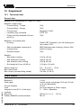
stated in the "Technical data" in the "Supplement".
Provide a reliable separation between the supply circuit and
the mains circuits acc. to DIN VDE 0106 part 101. The VEGA
power supply units VEGATRENN 149AEx, VEGASTAB 690,
VEGADIS 371 as well as all VEGAMETs meet this requirement.
Bear in mind the following factors regarding supply voltage:
l
30027-EN-060224
l
the reduction of the output voltage of the power supply unit
under nominal load (with a sensor current of 20.5 mA or
22 mA in case of fault signal)
The influence of additional instruments in the circuit (see
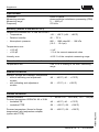
load values in "Technical data").
Select connection cable
VEGACAL 63 is connected with standard two-wire cable
without screen. A outer cable diameter of 5 … 9 mm ensures
the seal effected of the cable gland. If electromagnetic
interference is expected which is above the test values of
EN 61326 for industrial areas, screened cable should be used.
For HART multidrop operation we recommend as standard
practice the use of screened cable.
Cable gland ½ NPT
On VEGACAL 63 with cable gland ½ NPT and plastic housing,
a metal ½" threaded insert is moulded in the plastic housing.
VEGACAL 63 - 4 … 20 mA/HART
15