1
X-3D-BL ResearchPilot User’s Manual V1.3b
X-3D-BL ResearchPilot User’s Manual
Inhaltsverzeichnis
1 Introduction
1.1 System overview . . . . . . . . . . . . . . .
1.1.1 X-CSM . . . . . . . . . . . . . . . .
1.1.2 X-Base . . . . . . . . . . . . . . . .
1.1.3 ResearchPilot . . . . . . . . . . . . .
1.1.4 Motors . . . . . . . . . . . . . . . .
1.1.5 X-BLDC brushless motor controllers
1.1.6 X-ACC . . . . . . . . . . . . . . . .
1.2 Transmitter . . . . . . . . . . . . . . . . . .
.
.
.
.
.
.
.
.
4
4
4
4
6
6
6
6
7
2 Things to do before the first flight
2.1 Mounting the propellers . . . . . . . . . . . . . . . . . . . . . . . . . . . . . . . . . . . . .
2.2 Preparing your own battery . . . . . . . . . . . . . . . . . . . . . . . . . . . . . . . . . . .
2.3 Teach-in of your transmitter . . . . . . . . . . . . . . . . . . . . . . . . . . . . . . . . . .
8
8
8
9
3 Operating the X-3D-BL ResearchPilot
3.1 Important things to keep in mind . . . . . .
3.2 Hints for using the X-ACC mode . . . . . .
3.2.1 Trim memory function . . . . . . .
3.2.2 Optimisation of the pressure sensor
3.2.3 Control modes X-3D ResearchPilot
3.2.4 Height control . . . . . . . . . . .
3.3 First flight . . . . . . . . . . . . . . . . . .
3.3.1 X-3D-ResearchPilot Parameter . . .
4 On-Board serial interface
4.1 Physical interface . . . . . . . . . . . . .
4.2 Data protocol . . . . . . . . . . . . . . .
4.2.1 Data output . . . . . . . . . . . .
4.2.2 Command input . . . . . . . . . .
4.3 Test software . . . . . . . . . . . . . . .
4.4 General hints for using the serial interface
.
.
.
.
.
.
.
.
.
.
.
.
.
.
.
.
.
.
.
.
.
.
.
.
.
.
.
.
.
.
.
.
.
.
.
.
.
.
.
.
.
.
.
.
.
.
.
.
.
.
.
.
.
.
.
.
.
.
.
.
.
.
.
.
.
.
.
.
.
.
.
.
.
.
.
.
.
.
.
.
.
.
.
.
.
.
.
.
.
.
.
.
.
.
.
.
.
.
.
.
.
.
.
.
.
.
.
.
.
.
.
.
.
.
.
.
.
.
.
.
.
.
.
.
.
.
.
.
.
.
.
.
.
.
.
.
.
.
.
.
.
.
.
.
.
.
.
.
.
.
.
.
5 Software updates and system configuration changes
5.0.1 Software update of the X-3D-FunPilot . . . . . .
5.1 Software update of the X-Base . . . . . . . . . . . . . .
5.2 Setting up the X-BLDC brushless motor controllers . . .
5.3 X-3D Parameters . . . . . . . . . . . . . . . . . . . . .
5.4 Calibration of the acceleration sensors . . . . . . . . . .
Ascending Technologies GmbH
-2-
.
.
.
.
.
.
.
.
.
.
.
.
.
.
.
.
.
.
.
.
.
.
.
.
.
.
.
.
.
.
.
.
.
.
.
.
.
.
.
.
.
.
.
.
.
.
.
.
.
.
.
.
.
.
.
.
.
.
.
.
.
.
.
.
.
.
.
.
.
.
.
.
.
.
.
.
.
.
.
.
.
.
.
.
.
.
.
.
.
.
.
.
.
.
.
.
.
.
.
.
.
.
.
.
.
.
.
.
.
.
.
.
.
.
.
.
.
.
.
.
.
.
.
.
.
.
.
.
.
.
.
.
.
.
.
.
.
.
.
.
.
.
.
.
.
.
.
.
.
.
.
.
.
.
.
.
.
.
.
.
.
.
.
.
.
.
.
.
.
.
.
.
.
.
.
.
.
.
.
.
.
.
.
.
.
.
.
.
.
.
.
.
.
.
.
.
.
.
.
.
.
.
.
.
.
.
.
.
.
.
.
.
.
.
.
.
.
.
.
.
.
.
.
.
.
.
.
.
.
.
.
.
.
.
.
.
.
.
.
.
.
.
.
.
.
.
.
.
.
.
.
.
.
.
.
.
.
.
.
.
.
.
.
.
.
.
.
.
.
.
.
.
.
.
.
.
.
.
.
.
.
.
.
.
.
.
.
.
.
.
.
.
.
.
.
.
.
.
.
.
.
.
.
.
.
.
.
.
.
.
.
.
.
.
.
.
.
.
.
.
.
.
.
.
.
.
.
.
.
.
.
.
.
.
.
.
.
.
.
.
.
.
.
.
.
.
.
.
.
.
.
.
.
.
.
.
.
.
.
.
.
.
.
.
.
.
.
.
.
.
.
.
.
.
.
.
.
.
.
.
.
.
.
.
.
.
.
.
.
.
.
.
.
.
.
.
.
.
.
.
.
.
.
.
.
.
.
.
.
.
.
.
.
.
.
.
.
.
.
.
.
.
.
.
.
.
.
.
.
.
.
.
.
.
.
.
.
.
.
.
.
.
.
.
.
.
.
.
.
.
.
.
.
.
.
.
.
.
.
.
.
.
.
.
.
.
.
.
.
.
.
.
.
.
.
.
.
.
.
.
.
.
.
.
.
.
.
.
.
.
.
.
.
.
10
10
10
11
11
12
12
12
13
.
.
.
.
.
.
14
14
15
15
18
21
22
.
.
.
.
.
23
23
23
24
25
25
www.asctec.de
X-3D-BL ResearchPilot User’s Manual
6 Contact Information
26
A Troubleshooting
A.1 Slight tilt in pitch/roll with the pitch/roll stick in neutral position
A.2 Considerable tilt in pitch or roll . . . . . . . . . . . . . . . . . .
A.3 Bad reception during flight . . . . . . . . . . . . . . . . . . . .
A.4 The red LED on the X-3D keeps blinking after the startup . . . .
A.5 The X-3D-BL turns itself off during flight . . . . . . . . . . . .
27
27
27
27
28
28
B User-programmable startup melodies
Ascending Technologies GmbH
.
.
.
.
.
.
.
.
.
.
.
.
.
.
.
.
.
.
.
.
.
.
.
.
.
.
.
.
.
.
.
.
.
.
.
.
.
.
.
.
.
.
.
.
.
.
.
.
.
.
.
.
.
.
.
.
.
.
.
.
.
.
.
.
.
.
.
.
.
.
.
.
.
.
.
29
-3-
www.asctec.de
X-3D-BL ResearchPilot User’s Manual
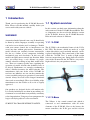
1 Introduction
Thank you for purchasing the X-3D-BL ResearchPilot. Please read this manual carefully before you
start to work with your new vehicle.
WARNING!
A motorized model aircraft is not a toy! It should only
be flown by adults. Improper assembly or operating
can lead to severe injuries and / or damages. Trouble
with your remote control due to interferences can
occur any time without prior notice. Sometimes, a
model aircraft can suddenly become uncontrollable due to a failure of any component, including
mechanical parts and electronics. In this case, the
model can rapidly move towards any direction. Make
sure you always keep a safe distance to people,
animals, obstacles or things of any kind, traffic roads,
etc.. There are country-specific laws regulating the
operation of model aircrafts that definitely have to
be obeyed. Furthermore, we strongly recommend to
effect a liability insurance for model aircrafts. The
manufacturer and your dealer of the X-3D-BL do
not have any influence on, nor can they monitor the
correct assembly and proper operation of your model
aircraft. Always be aware of the dangers mentioned
above and act accordingly. There is no liability of the
manufacturer nor the retailer at all, as far as legally
approved.
1.1 System overview
In this section you find some information about the
subsystems used in the X-3D-BL ResearchPilot. These components are also used in the hobbyist version
of the X-3D-BL, however, the X-3D-BL ResearchPilot on-board software is different.
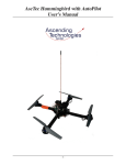
1.1.1 X-CSM
The X-CSM is the mechanical frame of the X-3DBL UFO. The booms, which are made of a rigid
carbon fiber-balsa wood sandwich material, can be
replaced individually. The central unit of the frame
called the ”X-CSM Core” is made of light weight
laser-cut magnesium parts. Being built out of these
state-of-the-art materials the X-CSM is a very robust
high-tech basis for your quadrotor aircraft.
Our products are designed for the civil market only.
It is strictly forbidden to use them in any military environment or to retail them to any military or military
related organization. Using any of our components for
1.1.2 X-Base
larger scale flying objects is also not allowed.
SUBJECT TO CHANGE WITHOUT NOTICE.
Ascending Technologies GmbH
The X-Base is the central control unit which is
connected to and communicates with all active
elements of the X-3D-BL. Next to the battery, the
motor controllers, the X-3D gyro and the receiver
-4-
www.asctec.de
X-3D-BL ResearchPilot User’s Manual
you can also connect several LEDs to the X-Base to
give your X-3D-BL a unique fancy look.
1 BL-controllers / brushed motors (+)
2 BL-controllers (-)
3 Brushed motors (-) Left/Right/Back/Front
4 PPM-Receiver Input (-) (+) Signal
(from lower to upper connector)
5 LEDs (-) Left/Right/Rear/Front
6 LEDs (+) 5V
7 Power connector, (+) and (-) marked on the
upper side of the board
The key below the power connector (7) turns the
X-3D-BL on and off. A short press is enough to turn
the vehicle on. To turn it off the key has to be pressed
for at least 200ms.
The ”brushed motors” connectors of the X-Base (3)
are not required as the brushless motors are driven by
independent controllers, and thus the connectors can
be used to drive peripherals like for instance a nightflight kit. Connector ”L” is switched on and off by
R/C channel 5, connector ”R” by R/C channel 6. The
connectors can sink currents up to 5A if they’re enabled. That means that the (-)-input of a peripheral has
to be connected to the ”L” or ”R” pad and the (+)input has to be connected to (+) (connector (1)). Be
aware that in this configuration your peripheral will
be supplied the whole battery voltage. If this not what
An LED connected to the ”Front-LED” Pads on the you need make sure you use a suitable voltage regubottom side of the X-Base will always be on as long lator.
as the X-3D-BL is turned on. Such an LED can be
mounted to the very front of your vehicle to make it
easier for the pilot to know where the front side is.
Ascending Technologies GmbH
-5-
www.asctec.de
X-3D-BL ResearchPilot User’s Manual
1.1.3 ResearchPilot
1.1.4 Motors
The ResearchPilot is the sensor unit of the X-3D-BL. The X-BL-52s motors by HACKER Motors GermaWith three piezo-gyros, a high precision pressure ny are custom-built for the X-3D-BL. The motors are
sensor and highly optimized control loops it does perfectly suited for the application in this vehicle.
the actual flight/attitude control. All parameters
influencing the in-flight behavior can be tuned by
connecting the ResearchPilot to a PC using the
USB adapter that came with your X-3D-BL and the
X-Control software. Once you are on the field for
flying you can select four different parameter by stick
commands.
1.1.5 X-BLDC brushless motor
controllers
Every motor is controlled by an independent XBLDC brushless motor controller. The controllers are
highly optimized for the X-BL-52s motors and thus
ensure the highest efficiency possible. Please note that
for this reason the controllers might not work with a
different motor type.
LED patterns of the X-3D-ResearchPilot
• red: Initialisation
• red/yellow blinking: X-Base or X-BL motors
1.1.6 X-ACC
not detected
• red/yellow and green blinking: No RC recepti- The X-ACC is a tiny add-on module comprising a
on and ne setting selected
triaxial accelerometer.
• yellow and green blinking: No setting selected
• yellow blinking/green: Ready for flight
• yellow blinking: X-Base is in setup mode
• yellow/red: trim reset
• gelb: trim saved
Ascending Technologies GmbH
-6-
www.asctec.de
X-3D-BL ResearchPilot User’s Manual
Using the acceleration data the X-3D can compute the
absolute orientation of the vehicle in pitch and roll.
The datafusion is done with an update rate of 1kHz to
guarantee good stability. As a consequence, the helicopter is able to come back to a horizontal orientation
on its own. In the X-ACC mode the pilot - or your own
add-on electronics - command an absolute angle. The
further you push the pitch or roll stick, the bigger the
tilt-angle of the X-3D-BL. If you leave the stick centered the helicopter will come back to horizontal. In
this mode you are not able to do loops or flips, however, hovering and all 2D-maneuvers are much easier
to do. The X-ACC is also a great help for beginners!
In addition, the vehicle can be position stabilized by
a simple PD-Loop.
1.2 Transmitter
Any five or more channels R/C transmitter can be
used to operate the X-3D-BL ResearchPilot. Even if
it is controlled autonomously by your own controller
board, the transmitter is required as a backup. As a safety measure the X-3D-BL ResearchPilot is not able
to launch without a valid signal from the R/C transmitter.
Ascending Technologies GmbH
-7-
www.asctec.de
X-3D-BL ResearchPilot User’s Manual
2 Things to do before the first flight
The X-3D-BL is shipped completely assembled and
tested. You only have to do the following steps to make it work with in combination with your equipment.
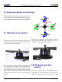
2.1 Mounting the propellers
To improve the durability of the propellers during a
The propellers can be slid over the axles and be faste- crash you can optionally add a cable tie (e.g. 2.5 x
ned using a plastic nut. Do not fasten the nut too tight, 100 mm) as seen in the following picture.
as this would bend the propellers.
Please note that there are two types of propellers: One 2.2 Preparing your own
pair of propellers is spinning clockwise, the other pair
battery
is spinning counterclockwise. The propellers spinning clockwise must be mounted to the front and
the rear motor, whereas the counterclockwise rotating You need a 3s (three cells, 11.1V) Lithium Polymer
propellers must be mounted to the left and to the right (LiPo) Battery. We recommend capacities between
motor.
1500 and 2100 mAh. With a state-of-the-art 2100
Ascending Technologies GmbH
-8-
www.asctec.de
X-3D-BL ResearchPilot User’s Manual
mAh battery the vehicle is able to hover up to 23 mi- by the software.
nutes without any payload, and up to 12 minutes with
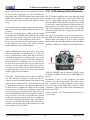
You can freely choose a stick on your R/C for eve200 g of payload.
ry function. If you are used to a certain configuration
Make sure you mount your battery such that it can you should definitely continue using this one. If you
definitely not get damaged by hitting the frame, even haven’t flown other model aircrafts before we recomin a crash. Otherwise the battery could explode! Here mend the following configuration (”Mode 2”):
is an example of how to mount a battery correctly:
The black foam on both sides hinders it from being
hurt by the magnesium parts of the frame. The
woodden plate on the bottom makes it stick to the
screw holding the bottom plate of the frame. Of
course, there are many different ways to prepare your
battery for a safe operation. This is only an example.
The X-3D-BL ResearchPilot works with any R/C
with at least five channels. Make sure that all chanLithium Polymer Batteries (LiPo) can be very nels work independently and that no mixers are active
dangerous if not handled correctly. Please read and in your remote.
follow the instructions of the battery and charger
manufacturers! Do never short circuit a LiPo battery Please make sure you assign a switch on your R/C
transmitter to the SW1-function, as you will need this
and use safe connectors!
channel to activete the serial interface onboard your
X-3D-BL ResearchPilot.
2.3 Teach-in of your
transmitter
If you want to use your own transmitter which
you did not purchase bundled with the X-3D-BL
ResearchPilot, please follow these steps:
First of all, you need to install the X-Control PCSoftware. If you didn’t receive a copy of it please contact us by e-mail. Connect the USB adapter to your
PC and to the X-Base, turn on your UFO, open the XControl software and click on ”X-Base” and then on
”Connect”. Then choose ”Receiver setup” and ”Automatic calibration”and follow the instructions given
Ascending Technologies GmbH
-9-
www.asctec.de
X-3D-BL ResearchPilot User’s Manual
3 Operating the X-3D-BL ResearchPilot
3.1 Important things to keep in
mind
• There is a battery warning implemented in your
X-3D-BL. A low battery is signalized by a periodic, simultaneous tremor of all motors. This
is hard to see but it can be heard. Depending on
the battery you use there is about a minute of
flight time left after the low-battery warning is
activated. Lithium Polymer (LiPo) batteries are
very vulnerable to deep discharge. That is why
the X-3D-BL turns off completely if the voltage drops under a programmable threshold. You
can adjust the thresholds for the low-battery warning and the low-battery shut down using the XControl software. Therefor you have to connect
the X-Base to your PC using the USB adapter
and click on ”X-Base”, ”Connect” and then on
”Parameters”.
• Directly after turning the X-3D-BL on the motors produce a short beep. It is perfectly normal
that the propellers move slightly during that tone.
• Keep the X-3D-BL totally still after turning it
on until the X-3D shows the yellow+green (no
reception) or green (ready to fly) light pattern.
Otherwise the sensors can not be calibrated correctly and the vehicle might go crazy after turning on the motors. If you accidentally moved
the system during startup simply turn it off and
on again.
• If the ambient temperature changes rapidly, for
instance when you leave a warm room, the
angles estimated by the datafusion algorithms
might not be totally correct. As a consequence
your vehicle would be tilted a bit, even with a
neutral pitch and roll command. In this case we
recommend to wait a few minutes, until all sensors have adopted to the ambient temperature.
• If only the green LED at the X-3D board is on
the vehicle is ready to fly. A yellow+green light
pattern means ”no reception”. In this case please check that your remote control is turned on
and fully functional, that the receiver crystal is
installed in the receiver and that the receiver is
connected correctly.
• After the startup phase the motors are still turned off and secured. To turn them on you have to
move the yaw stick to the very left or to the very
right while your throttle stick is in zero position.
The motors will then start and keep running at
their minimum speed. To turn the motors off you
have to do the same procedure again: Move the
yaw stick to the very left or to the very right while your throttle stick is in zero position. There
is no flight maneuver where one would use this
control input and thus you will not accidentally
turn off your motors during flight. For safety reasons you should turn off the motors immediately if one of the propellers touches the ground or
any other obstacle and hence the X-3D-BL ResearchPilot is not able to take off.
Ascending Technologies GmbH
3.2 Hints for using the X-ACC
mode
- 10 -
• In the X-ACC mode it is particularly important
that the vehicle is not moved at all during the
initialization. Calibration errors caused by shaking during startup will influence the performance much more than in the heading-hold mode. If
the vehicle tilts more and more after starting the
motors, it is very likely that it was moved during
the initialization. In this case, please turn it off
and on again and make sure that it is not moved until the X-3D displays the green+yellow or
green light pattern.
www.asctec.de
X-3D-BL ResearchPilot User’s Manual
• If your X-3D-BL has the X-ACC module and the
X-ACC firmwares installed it behaves different
in case of a reception loss. If there is no R/C signal it will activate the X-ACC mode, try to get
to a horizontal orientation and start to sink with
1/3rd of full throttle. It will keep this state until it regains reception. If one of the propellers is
blocked after the landing, the X-BLDC controllers will turn off the connected motor after 10
tries to restart it. Attention! With the X-ACC installed there is no audible signal if reception is
lost, as the motors are used to do a safe landing
instead of playing signal tones.
• If the ambient temperature changes rapidly, for
instance when you leave a warm room, the
angles measured by the X-3D and X-ACC might
not be totally correct. That means that your vehicle may be tilted a bit, even with the pitch and
roll stick centered and the trimmers in the right
position. In this case we recommend to wait a
few minutes, until all sensors have adopted to the
ambient temperature. You could also fly using
the Heading-Hold mode during that period, as it
is more robust against changes in temperature.
3.2.2 Optimisation of the pressure
sensor
The pressure sensor of the X-3D-ResearchPilot is
sensitive to light and air movements perpendicular the
the sensor opening (e.g. by wind during a forward
flight). Therefore it’s recommend for the best performance, especially outdoor, to add a small air filter to
the pressure sensor. A prooven technique uses some
schrinking tube and some foam (e.g. foam from the
X-3D-ResearchPilot box). Shrinking the schrinking
tube around the pressure sensor pin and carefully add
some super glue to make it hold better. Attention: It’s
3.2.1 Trim memory function
very important that absolutly NO superglue get’s into
the sensor! Otherwise this very expensive part can taThe X-3D and the X-3D-ResearchPilot are able to sa- ke damage! An alternative are sinter filter which you
ve the actual trim setting on your RC transmitter to can get in your modell store. The following pictures
enable smooth switching between X-ACC and hea- show both variants:
ding hold mode. Two functions can be selected with
the RC transmitter.
A simple method to correctly calibrate your trim memory:
• Reset trim memory (Motors off, full throttle, full
yaw to the right)
• Fly in the X-ACC mode and trim the UFO
• Land, stop motors and save the trim (Motors off,
full throttle, full yaw to the left)
• Set the trimmers on your remote to 0 and start
flying normally.
Ascending Technologies GmbH
- 11 -
www.asctec.de
X-3D-BL ResearchPilot User’s Manual
Attention: It’s very important to teach in the channels 5 and 6 in the X-Base receiver configuration!
Otherwise the UFO can get uncontrolable as it’s
switching modes undefenately.
3.2.4 Height control
The height controller is programmed as sink and
fall rate controller. Stick in the middle means: ”hold
height”. Starting from the ground is very easy. Just
push up the stick to full throttle until the UFO reached it’s desired height. Then put the stick back in the
middle. The UFO will try to hold it’s height as good
as it’s possible. This mode is more meant for outdoor
usage. The controller characteristics are calm and not
very agressive, so it’s possible and normal that the
UFO doesn’t climb to the desired height completlty
again afer a disturbance. Light and other air flows can
decrease the performance of the sensor. Using a air
filter is recommanded (see 3.2.2. It’s better to use a
3.2.3 Control modes X-3D
spring on the throttle stick as well if you fly often
ResearchPilot
with the height control. Otherwise it can be hard to
find the middle of the stick. The deadzone can be inThe X-3D-ResearchPilot has three different control creased in the parameter settings if it’s necessary. The
modes:
thrust pulsing battery warnung should be switched off
for the height control if you still want to fly with it at
• Heading Hold mode(HH)
empty battery conditions.
• X-ACC-mode
• X-ACC + height control Modus
3.3 First flight
Switching between the modes can be done in two different ways:
We recommend to do the first flights on some big
• 3-step switch teached in to channel 5 (SW1 in grassland, as the soft ground will soften possible
crashes. If you have never controlled an R/C aircraft
the X-Base configuration)
before you will have to practice a bit until you’re able
• 2-step switch teached in to channel 5 to switch to fly inside your lab.
between X-ACC and HH mode. A second switch
teached in to channel 6 (SW2) for enabeling the
Make sure that the battery is fully charged, connected
height control in X-ACC mode.
and mounted correctly. Switch on the vehicle and be
The recommanded default setting is the 3-step really careful during the startup phase. The vehicle
switch. Use the second mode RC transmitters wi- must NOT be moved during startup as the gyro
thout 3-step-switched. The mode can be changed sensors are being initialized! If the vehicle was
with the PC-Software seperately in every setting (in moved during startup simply turn it off and on again.
datafusion/misc).
The startup sequence is completed once the motors
start playing the preprogrammed music. Please be
Ascending Technologies GmbH
- 12 -
www.asctec.de
X-3D-BL ResearchPilot User’s Manual
aware, that the first ”beep” after turning the vehicle
on is part of the startup process. Once the music has
been played the X-3D will light the green and yellow
LEDs if the transmitter is turned off and only green
if a valid signal is detected. Now the vehicle is ready
to fly.
3.3.1 X-3D-ResearchPilot Parameter
The X-3D-ResearchPilot offers four onboard stored
parameter sets which can be selected my the RC. To
select a setting make sure, that the motors are switched off and the UFO has RC reception. The setting
is selected by giving full throttle and moving the pitch/roll stick to one of the four corners for a second.
To start the motors you have to move the left stick to
The UFO acknologes the selection by 1-4 beeps. The
the very left or right whilst holding throttle in zero
following image shows the stick positions for the difposition.
ferent settings.
If it is the first flight after a while or the first flight
at all hold your X-3D-BL ResearchPilot down to the The factory set parameters are already prepared for
floor. You can grab the center part of the frame, but the X-BL-Ufo. Therefore there is no direct need to
make sure that you don’t touch any of the rotors.
change them. Nevertheless, if you want to change
In case it tries to tilt in any direction and one or more them connect the X-USB module to the X-3D Reseof the propellers are going crazy: Please read the archPilot, switch on the UFO and start the PC softwatroubleshooting section of this manual.
re.
Angle stabilization in pitch and roll is active even
when the propellers are running idle. Use this feature as you hold the vehicle from below and tilt it
carefully to check that everything works. As you tilt
it to one direction you must feel some counterforce
from the motors if everything is o.k.. You can also try
to steer the pitch and roll axis and see that you can
directly steer the angles. Please check if the vehicle
is leveled in your hand with the pitch and roll stick
in neutral position. If not, correct any undesired tilt
with the pitch and roll trimmers.
Click on ”FP/OSP” and on connect to connect to the
X-3D-ResearchPilot. Click now on ”OSP Flight paraNow, give a little throttle and the vehicle should ho- meters”.
ver. Try hovering in a height of about 1m and concentrate on the red marking which is the front of your
vehicle. Try to compensate for any movement in yaw
by moving the yaw-stick in the opposite direction. It
is much easier to control the vehicle if red is facing
away from you, as in this case it will move away from
you if you push your pitch/roll stick away. It is perfectly normal that the vehicle drifts slowly in all directions. As long as you have not installed any external
tracking for position control, you have to compensate for these movements manually. After a few battery
charges you will able to fly in any room, and with some more practice you can even fly in small spaces and
land on tables etc.. Good luck!
Ascending Technologies GmbH
By clicking ”Load” or ”Save” parameter sets can be
stored on or loaded from the PC. The button ”transmit” transmits the actual parameterset, but doesn’t
store the setting on the UFO! Only a click on ”Write
parameters” writes the setting in the permanent memory of the UFO.
Click on ”Ready” and ”Transmit and disconnect” after you done.
- 13 -
www.asctec.de
X-3D-BL ResearchPilot User’s Manual
4 On-Board serial interface
4.1 Physical interface
The interface is a serial uart link with 3.3V TTL levels which is 5V tolerant at 57600 baud, 8 bits, one startbit,
one stopbit. To connect a PC, a bluetooth link or a high level processor to the ResearchPilot you can use the
same interface as the USB interface:
Pin 1
Pin 2
Pin 3
Pin 4
Pin 5
Pin 6
Pin 7
Pin 8
GND
GND
RXD(input)
NC
TXD(output)
CTS(input)
VCC (4.3V)
VCC (4.3V)
Be carefull with the VCC power supply. It’s connected to the analog supply of the pressure sensor and
is very sensitive to noise. Depending on the needed power it might be neccessary to connect the power
of your transmitter directly to the battery power (12V pins on the X-Base).
Tie CTS to GND for continuous data transfer.
Ascending Technologies GmbH
- 14 -
www.asctec.de
X-3D-BL ResearchPilot User’s Manual
Alternatively, you can use the pin as an input for a radio modem’s CTS (Clear To Send) pin. The X-3D-BL
ResearchPilot will only send data if the CTS pin is pulled low by the connected device. It will stop sending
data if the Pin is pulled high by the modem to prevent data loss during the transmission.
4.2 Data protocol
4.2.1 Data output
The data output protocol is a very flexible user programable serial protocol. By sending a configuration
packet to the ResearchPilot the data packet can be changed to a user configuration. Through the command
data packet, the desired data rate can be set in 5Hz steps from 5Hz up to 300Hz which is automaticly handled
by the ResearchPilot. The data packet can be configured to contain any arbitrary combination of the values
from the following table. The standard packet is configured as:
ID
ID
ID
ID
ID
ID
ID
ID
ID
ID
ID
ID
ID
ID
ANGLE PITCH
ANGLE ROLL
ANGLE YAW
AV PITCH
AV ROLL
AV YAW
ACC X
ACC Y
ACC Z
HEIGHT
RC CHAN0
RC CHAN1
RC CHAN2
RC CHAN3
The configuration packet is descriped in Section 4.2.1.
Ascending Technologies GmbH
- 15 -
www.asctec.de
X-3D-BL ResearchPilot User’s Manual
Name
ID
gyro pitch
gyro roll
gyro yaw
acc x
acc y
acc z
mag x
mag y
mag z
pressure
temperature
ID
ID
ID
ID
ID
ID
ID
ID
ID
ID
ID
angle
angle
angle
angle
angle
ID
ID
ID
ID
ID
pitch
roll
yaw
pitch acc
pitch roll
angvel pitch
angvel roll
angvel yaw
ID
ID
ID
acc
acc
acc
acc
ID
ID
ID
ID
x
y
z
absolute length
trans acc x
trans acc y
trans acc z
ID
ID
ID
mag
mag
mag
mag
x
y
z
heading
ID
ID
ID
ID
height (filtered)
dheight (filtered)
height reference
dheight
speed z
ID
ID
ID
ID
ID
ID#
Size Type valid Values
Raw data
RAW GYRO PITCH
0x01 2
short 0..1023
RAW GYRO ROLL
0x02 2
short 0..1023
RAW GYRO YAW
0x03 2
short 0..1023
RAW ACC X
0x04 2
short 0..1023
RAW ACC Y
0x05 2
short 0..1023
RAW ACC Z
0x06 2
short 0..1023
RAW MAG X
0x07 2
short 0..1023
RAW MAG Y
0x08 2
short 0..1023
RAW MAG Z
0x09 2
short 0..1023
RAW PRESSURE
0x0A 4
int
−231 ..231
RAW TEMP
0x0B 4
int
−231 ..231
Calculated data
Angles
ANGLE PITCH
0x0C 4
int
-90000..+90000
ANGLE ROLL
0x0D 4
int
-90000..+90000
ANGLE YAW
0x0E 4
int
0..+360000
ANGLE PITCH ACC
0x0F 4
int
-90000..+90000
ANGLE ROLL ACC
0x10 4
int
-90000..+90000
Angular velocities
AV PITCH
0x11 4
int
-512..+512
AV ROLL
0x12 4
int
-512..+512
AV YAW
0x13 4
int
-512..+512
Accelerations
ACC X
0x14 2
short -1500..1500
ACC Y
0x15 2
short -1500..1500
ACC Z
0x16 2
short -1500..1500
ACC LENGTH
0x17 2
short 0..1500
translational accelerations (pseudo values)
TRANS ACC X
0x18 2
short −215 ..215
TRANS ACC Y
0x19 2
short −215 ..215
TRANS ACC Z
0x1A 2
short −215 ..215
magnetic field (calibrated)
MAG X
0x1B 4
int
-512..512
MAG Y
0x1C 4
int
-512..512
MAG Z
0x1D 4
int
-512..512
MAG HEADING
0x1E 4
int
0..360000
Height)
HEIGHT
0x1F 4
int
−231 ..231
DHEIGHT
0x20 4
int
−231 ..231
HEIGHT REFERENCE
0x21 4
int
−231 ..231
DHEIGHT REFERENCE 0x22 4
int
−231 ..231
SPEED Z
0x23 4
int
−231 ..231
Ascending Technologies GmbH
- 16 -
Unit
Raw
Raw
Raw
Raw
Raw
Raw
Raw
Raw
Raw
Raw
Raw
1/1000◦
1/1000◦
1/1000◦
1/1000◦
1/1000◦
0, 79 ∗ ◦ /s
0, 79 ∗ ◦ /s
0, 79 ∗ ◦ /s
mg
mg
mg
pseudovalue
pseudovalue
pseudovalue
no unit
no unit
no unit
1/1000◦
mm (relative)
mm/s
mm (relative)
mm/s
pseude Z speed
www.asctec.de
X-3D-BL ResearchPilot User’s Manual
Name
ID
ID#
pitch
roll
yaw
thrust
ID
ID
ID
ID
CO
CO
CO
CO
PITCH
ROLL
YAW
THRUST
0x24
0x25
0x26
0x27
lock
channel0
channel1
channel2
channel3
channel4
channel5
channel6
channel7
ID
ID
ID
ID
ID
ID
ID
ID
ID
RC
RC
RC
RC
RC
RC
RC
RC
RC
LOCK
CHAN0
CHAN1
CHAN2
CHAN3
CHAN4
CHAN5
CHAN6
CHAN7
0x28
0x29
0x2A
0x2B
0x2C
0x2D
0x2E
0x2F
0x30
uptime
voltage
current
cpu load
ID
ID
ID
ID
UPTIME
VOLTAGE
CURRENT
CPULOAD
0x31
0x32
0x34
0x33
Size Type
Controller Data
control outputs
4
int
4
int
4
int
4
int
RC data
2
short
2
unsigned short
2
unsigned short
2
unsigned short
2
unsigned short
2
unsigned short
2
unsigned short
2
unsigned short
2
unsigned short
Misc
4
int
4
int
2
unsigned short
2
unsigned short
valid Values
Unit
−231 ..231
−231 ..231
−231 ..231
−231 ..231
0..200, 100=middle
0..200, 100=middle
0..200, 100=middle
0..200
0..1
0..4096
0..4096
0..4096
0..4096
0..4096
0..4096
0..4096
0..4096
1=lock
0..232
0..255
0..65535
0..1000
seconds
battery voltage in 1/10V
current in 1/100A
cycles per second
The Researchpilot also outputs a status data packet ones every command packet is send which has this structure:
struct SCIENTIFIC_STATUSDATA
{
//alway = PD_SCIENTIFICSTATUS
//#define PD_SCIENTIFICSTATUS
0x18
unsigned char packetdescriptor;
//flags
//Bit 0-5 represent the actual status of the ResearchPilot!
if the interface is disabled by the remote, all bits are 0!
//Bit 0(0x01): Pitch control through serial interfacae enabled
//Bit 1(0x02): Roll control through serial interface enabled
//Bit 2(0x04): Thrust control through serial interface enabled
//Bit 3(0x08): Yaw control through serial interface enabled
//Bit 4(0x10): ACC-Mode on/off
//Bit 5(0x20): Height control - on/off (only with ACC)
//Bit 6(0x40): unused
//Bit 7(0x80): Scientific interface enabled by Remote?
1=Interface enabled (control through serial link)
0=interface disabled (control through RC)
//Bit 8..15: sendrate of the scientific packet in 5Hz
(0=off;1=5Hz, 20=100Hz, 200=1kHz). Scientific packet
is send for three seconds max. after the last command_data packet
unsigned short flags;
Ascending Technologies GmbH
- 17 -
www.asctec.de
X-3D-BL ResearchPilot User’s Manual
};
4.2.2 Command input
All packets send to the X-3D ResearchPilot have the following frame format:
Startbyte 1: >
Startbyte 2: ∗
Startbyte 3: >
Length of dat in bytes (high byte)
Length of data in bytes (low byte)
DATA
CRC16 of data (high byte)
CRC16 of data (low byte)
Length and CRC16 are unsigned short types.
For calculating the CRC16 of a packet you can use the following algorithm:
//update crc with data
unsigned short crc_update(unsigned short crc,unsigned char data)
{
data ˆ= (crc & 0xff);
data ˆ= data << 4;
return ((((unsigned short )data << 8) | ((crc>>8)&0xff))
ˆ (unsigned char )(data >> 4) ˆ ((unsigned short )data << 3));
}
//calculate the CRC16 of an array of bytes with the length cnt
unsigned short crc16(void* data, unsigned short cnt)
{
unsigned short crc=0xff;
unsigned char * ptr=(unsigned char *) data;
int i;
for (i=0;i<cnt;i++)
{
crc=crc_update(crc,*ptr);
ptr++;
}
return crc;
}
Sending the packet in pseude-c-code would look like this:
struct SCIENFITIC_COMMANDDATA scientificCommandData;
void sendCommandPacket()
{
Ascending Technologies GmbH
- 18 -
www.asctec.de
X-3D-BL ResearchPilot User’s Manual
unsigned short crc;
unsigned char b;
unsigned char ptr;
unsigned short length;
ptr=&(scientificCommandData.packetdescriptor);
length=sizeof(scientificCommandData);
//check if serial link is open
if (!UartInitialized())
return;
//calculate CRC
crc=crc16(ptr,length);
//send packet
WriteStringToUart(’>*>’);
WriteByteToUart(length>>8);
WriteByteToUart(length&0xff);
WriteArrayToUart(ptr,length);
WriteByteToUart(crc>>8);
WriteByteToUart(crc&0xff);
}
All WriteXToUart“ functions have to be replaced by user specific access to an open serial link.
”
With the command protocol a single or all control channels can be taken over by the serial interface.
Therefore the X-3D-BL ResearchPilot must receive the following command data packet with an update rate
of at least 10Hz to 20Hz up to 200Hz over the serial link:
struct SCIENFITIC_COMMANDDATA
{
//always 0x17
unsigned char packetdescriptor;
//pitch,
unsigned
unsigned
unsigned
unsigned
roll,
short
short
short
short
//flags
//Bit 0(0x01):
//Bit 1(0x02):
//Bit 2(0x04):
//Bit 3(0x08):
//Bit 4(0x10):
//Bit 5(0x20):
thrust, yaw commands. 0..4095 2048=middle
pitch;
roll;
thrust;
yaw;
Pitch control through serial interfacae enabled
Roll control through serial interface enabled
Thrust control through serial interface enabled
Yaw control through serial interface enabled
ACC-Mode on/off
Height control - on/off (only with ACC)
Ascending Technologies GmbH
- 19 -
www.asctec.de
X-3D-BL ResearchPilot User’s Manual
//Bit 6(0x40): overwrite ACC/Height mode control
//(0=mode selected by RC 1=mode selected by Bit 4 and 5)
//Bit 7(0x80): Trigger Scientific status packet (triggers a
//with the actual scientific state)
//Bit 8..15: sendrate of the scientific packet in 5Hz
//(0=off;1=5Hz, 20=100Hz, 200=1kHz)
response
//Scientific packet is send for three seconds max.
//after the last command_data packet
unsigned short flags;
};
Explanation of the command packet:
• packetdescriptor: Packet identifier; must always be 0x17.
• pitch: pitch value. 0..4095, 2048=middle
• roll: roll value. 0..4095, 2048=middle
• thrust: thrust value. 0..4095
• yaw: yaw value. 0..4095, 2048=middle
• flags: Flags:
Bit 0(0x01): Pitch control through serial interface enabled
Bit 1(0x02): Roll control through serial interface enabled
Bit 2(0x04): Thrust control through serial interface enabled
Bit 3(0x08): Yaw control through serial interface enabled
Bit 4(0x10): ACC-Mode on/off
Bit 5(0x20): Height control - on/off (only with ACC)
Bit 6(0x40): overwrite ACC/Height mode control (0=mode selected by RC 1=mode selected by
Bit 4 and 5)
Bit 7(0x80): Trigger Scientific status packet (triggers a response with the actual scientific state)
Bit 8..15: sendrate of the scientific packet in 5Hz (0=off;1=5Hz, 20=100Hz, 200=1kHz). Scientific packet is send for three seconds max. after the last command data packet
The pitch and roll value can be converted to absolute angles in the ACC-Mode by the following formula:
Ascending Technologies GmbH
- 20 -
www.asctec.de
X-3D-BL ResearchPilot User’s Manual
angle = value ∗ K stick XXXX in 1/1000◦
For the yaw the following formula can be used to calculate the desired angular velocity:
angle vel = (value ∗ K stick yaw)/2048 in ◦ /s
In heading hold mode, the K stick XX expo parameters should be set to zero for a linear output equation:
angle vel = (value ∗ K stick XXXX HH)/65536 in 1/1000◦ /s
As a safety precaution the vehicle will switch back to the transmitter and thus manual control after 100ms
not receiving data from the serial link.
The scientific config packet is used to set the desired data structure. The packet structure is:
struct SCIENTIFIC_CONFIG
{
//always PD_SCIENTIFICCONFIG
//#define PD_SCIENTIFICCONFIG
0x20
unsigned char packetdescriptor;
unsigned char data_select[128];
}
data select holds a list of up to 128 ID-Values which define the data which is included in the scientific data
structure.
The scientific data structure send out by the ResearchPilot is:
struct SCIENTIFIC_DATA
{
//always PD_SCIENTIFICDATA
//#define PD_SCIENTIFICDATA
0x19
unsigned char packetdescriptor;
//length of data field in bytes. Packetlength= length + 4
unsigned char length;
//flexible data field. Maximum 32 integers or 64 shorts.
unsigned char data[128];
};
The data field contains the data in any arbitrary order descriped in chapter 4.2.1. The data bytes are distributed
according the order and length of the requested data fields. A byte uses one byte of space whereas a short
uses two bytes and an int uses 4 bytes.
4.3 Test software
There is a graphical user interface (X-3D-BL ResearchPilot Testsoftware.exe) to visualize the data packets
described above. You can use this program to better understand the serial interface and to check if everything
is working correctly.
Ascending Technologies GmbH
- 21 -
www.asctec.de
X-3D-BL ResearchPilot User’s Manual
If you did not receive a copy of this software please contact us by e-mail.
4.4 General hints for using the serial interface
To enable the command interface, the vehicle must have a stable link to a normal RC transmitter (green
light on the X-3D!) and the SW1 function (see ”Receiver Setup” in the X-Control software with the X-Base
connected) must be >128 to activate the commands from the interface. This is a safety function as well. A
skilled pilot should always be ready to take over by setting the SW1 function back to 0 (e.g. with a switch) to
take control, if your high level control is not functioning as desired. The pilot also has to steer all functions
that are not activated in the channel select byte. Consequently you can activate one function after another,
which makes setting up and tuning high-level control loops much easier.
Ascending Technologies GmbH
- 22 -
www.asctec.de
X-3D-BL ResearchPilot User’s Manual
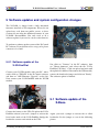
5 Software updates and system configuration changes
The X-3D-BL is shipped with a fully functional
firmware installed on all components. Please do not
upload any code from our public servers, as these
versions do not offer the additional features of your
X-3D-BL ResearchPilot. You only need to do a
software update if you receive a new version from us.
To perform a software update you need the X-Control
PC-software. If you did not receive a copy of it, please
contact us via e-mail.
5.0.1 Software update of the
X-3D-FunPilot
Not click on ”Connect” in the PC software, then
on ”Choose firmware” and seleect the file ”X-3DFunPilot VX.X.hey”. Click on upload and wait until
Connect your X-USB module with your PC. After- the uploaded is finished. Disconnect the USB module,
wards click on ”FP/OSP” in the X-Control software remove the bootloader jumper and click on ”Ready”.
and then on ”OSP Firmware Upgrade” on the left. The software update is finished.
Now connect your X-3D-FunPilot with the X-USB
module.
5.1 Software update of the
X-Base
Connect the battery to the UFO. To update the X-3DFunPilot software you need a jumper to activate the Again, you need a jumper to activate the so called
boot loader mode of the X-3D-FunPilot. Bridge the bootloader. Set the jumper as seen in the following
bootloader contacts and switch on the UFO.
picture.
Ascending Technologies GmbH
- 23 -
www.asctec.de
X-3D-BL ResearchPilot User’s Manual
5.2 Setting up the X-BLDC
brushless motor
controllers
The X-Base will not recognize all motors before they
have been set up correctly. This is absolutely normal!
Not until a successful configuration the X-Base will
recognize all X-BLDC controllers and the X-3D-BL
UFO will signal ”ready to fly”.
Connect the battery to the X-3D-BL, turn it on and
Open the X-Control software, click on ”X-Base” and connect the USB adapter with your computer and
then on ”X-Base firmware Upgrade” on the left hand then with the X-Base.
side. Turn on the X-Base (In this case the battery has
to be connected to the vehicle!) and connect the USB
adapter to the X-Base.
Choose the serial port (normally ”Autoselect:
COMxx”) and click on ”connect”. Select the ”*
ACT receiver.xbs” firmware file if you are using an
ACT receiver (35 or 40 MHz) or select the ”* PPM
receiver.xbs” if you are using a different receiver.
Then click on ”Upload”, wait for the upload to be
completed, disconnect the USB adapter from the
X-Base, remove the bootloader jumper and click
on ”Finished”. The X-Base software update is now
completed.
Open the X-Control software and click on ”X-Base”.
Choose the correct COM-Port (normally ”Autoselect:
COMxx”) and click on ”Connect”. Chose ”X-BL
Setup” and click on ”start search”. After several
seconds four brushless controllers with different
serial numbers should appear in the list. If less than
four controllers appear, turn of your X-3D-BL, check
all solderings and connectors and repeat the previous
steps.
If all four controllers have been found, click on
”config” and follow the instructions given by the
software in order to tell each controller its own
position and the appropriate turning direction. After
that, click on ”Disconnect” to complete the controller
setup.
Optionally a startup melody can be installed using the
X-BL update function. A detailed description of how
Ascending Technologies GmbH
- 24 -
www.asctec.de
X-3D-BL ResearchPilot User’s Manual
to do this can be found in appendix B.
5.3 X-3D Parameters
If you connect the X-3D to the X-Control software
without the bootloader jumper set, you can change all
parameters influencing the system behaviour. You can
also save a set of parameters to port it to a second
vehicle, or you can upload a set of parameters which
you received from us.
5.4 Calibration of the
acceleration sensors
The X-3D-BL ResearchPilot comes fully calibrated.
However, if something goes really wrong and for some reason you need to recalibrate the accelerometers,
here is what you have to do.
Connect the X-Base with the X-Control software,
open the X-ACC setup and follow the instructions
given by the wizard. To achieve the best performance
it is very important that the calibration is done very
precise. Please check that after the calibration the
X- and Y-outputs are roughly zero and the Z-output
is roughly -1000 if the X-3D-BL is standing in a
horizontal orientation. The automatic calibration
gives usable results, but sometimes the values can
still be optimized manually. Please also check the
scale factors, i.e. see, if all sensor outputs are about
±1000 if you hold the vehicle with the respective
axis in a vertical orientation. If everything seems
o.k. you can finalize the calibration by clicking on
”Finished” and on ”Transmit and disconnect”.
Ascending Technologies GmbH
- 25 -
www.asctec.de
X-3D-BL ResearchPilot User’s Manual
6 Contact Information
Ascending Technologies GmbH
Graspergerstr. 8
82131 Stockdorf
GERMANY
Phone: +49 89 89949847
E-Mail: [email protected]
Web: www.asctec.de
CEOs:
Michael Achtelik, Klaus-Michael Doth
Dipl.-Ing. Daniel Gurdan, Dipl.-Ing. Jan Stumpf
Handelsregister M¨unchen: HRB 166748
Ust.-ID: DE254728199
Ascending Technologies GmbH
- 26 -
www.asctec.de
X-3D-BL ResearchPilot User’s Manual
A Troubleshooting
This chapter holds solutions to problems which might
occur during the operation of your X-3D-BL UFO.
A.1 Slight tilt in pitch/roll with
the pitch/roll stick in
neutral position
Due to unavoidable measurement errors it is perfectly
normal, that your X-3D-BL is not always flying
exactly leveled in the X-ACC mode. However, a
slight tilt can easily be compensated by the trimmers
on your remote control.
A.2 Considerable tilt in pitch
or roll
There are some situations where the measured angle
can considerably differ from the real angle, which results in big tilt-angles in pitch and/or roll while the
pitch/roll stick on your remote is centered. This can
have the following reasons:
USB adapter and open the X-Control software to
check if all channels are detected as centered if
the sticks on the R/C are centered. If this is not
the case repeat the teach-in of your R/C following the instructions given by the software.
• Faulty calibration of the accelerometers: If after restarting the X-3D-BL the unwanted tilt is
still there and cannot be compensated using the
trimmers on your remote, please check the calibration of your X-ACC (cf. 5.4).
• Rapid change of the ambient temperature: If you
notice a considerable tilt in pitch or roll directly after you leave a warm room in winter or an
air-conditioned room in summer, please wait a
few minutes, until all sensors have adopted to the
new ambient temperature. Alternatively, you can
use the Heading-Hold mode during that period,
as this mode behaves much more robust during
fast temperature changes.
• Extremely fast maneuvers: Also fast maneuvers,
which result in high accelerations interacting
with your aircraft, can cause faulty measurements. If you fly several circles in a row in high
speeds it can happen, that the measured angle
differs several degrees from the real angle. If this
is the case, you simply have to fly gently or hover for a few seconds until the unwanted tilt is
gone.
• Shaking during initialization: In the X-ACC mode it is particularly important that the vehicle is
not moved at all during the initialization. Calibration errors caused by shaking during startup
will influence the performance much more than
in the heading-hold mode. If the vehicle tilts mo- A.3 Bad reception during flight
re and more after starting the motors it is very
likely that it was moved during the initialization.
If the X-3D-BL does not react while it is airborne,
In this case, please turn it off and on again and
please check if someone else uses the same channel.
make sure that it is not moved until the X-3D
Make sure your TX battery is fully charged and that
displays the green+yellow or green light pattern.
the antenna is fully extended. If you are still having
• Teach-in of your transmitter was not correct: To trouble you can to the following test to check the
check if your transmitter was taught-in correctly, range of your R/C system:
please connect the X-Base to your PC using the
Ascending Technologies GmbH
- 27 -
www.asctec.de
X-3D-BL ResearchPilot User’s Manual
During the range check all other transmitters should
be switched off. The best location to do the test is a
big open field, as metallic objects like cars or wire
fences could influence the result. You need a helper
who holds your transmitter with the antenna as close
to vertical as possible. Turn the X-3D-BL on and wait
until only the green LED on the X-3D is on signalizing ”ready to fly”. Then walk away from the transmitter until the yellow LED starts flickering. At this
point you should be at least 100 m away from your
TX. Repeat the whole procedure with the motors running at minimum throttle. If at a distance of about 100
m the signal is still o.k. (i.e. only the green is LED
on), your reception is totally fine. Due to the size of
the aircraft and the associated visibility you will never fly any further away than that. If the yellow LED
comes up randomly at shorter distances your TX/RX
combination is to weak. In this case you can try extending the antenna of the X-3D-BL by using a longer
plastic tube or stick which holds the antenna. A fully extended antenna works definitely better than one
which is wound around a stick as described in this manual. If you use a stub antenna at your TX this could
also be the reason for a bad reception, as such antennas do not transmit the full power. In this case try
using a standard telescopic antenna instead.
connect the X-Base to the X-Control software it will
show you which of the motors is not working correctly.
A.5 The X-3D-BL turns itself
off during flight
Please make sure that the current limit of your X-Base
is set to 35 A. To do so, please connect the X-Base
to the X-Control software and click on ”parameters”.
The value of the edit-field designated with ”Current:”
must be 35. Once you are done click on ”Finished”
and then on ”Transmit and disconnect”.
A.4 The red LED on the X-3D
keeps blinking after the
startup
If you have not configured your X-3D-BL using the
X-Control software as described above this behavior
is normal. In this case please follow the instructions
given in ??. If the configuration of your vehicle was
completed successfully the blinking red LED means
that one of the motor controllers or motors was not
detected. Please check if all four cables in black and
blue color between the X-Base and the motor controllers are connected correctly. If all connections are o.k.
please verify that all motors produce a short beep directly after you turn the X-3D-BL on. If one of them
does not play the sound check the power connection
of the affected motor controller. Are all wires o.k.?
Are all soldering points clean and correct? If you
Ascending Technologies GmbH
- 28 -
www.asctec.de
X-3D-BL ResearchPilot User’s Manual
B User-programmable startup melodies
The X-3D-BL ResearchPilot is capable of playing
preprogrammed melodies directly after the initialization. To upload a melody please connect the battery to
the X-3D-BL, turn it on and connect the USB adapter
with your computer and then with the X-Base.
Open the X-Control software and click on ”X-Base”.
Choose the correct COM-Port (normally ”Autoselect:
COMxx”) and click on ”Connect”. Chose ”X-BL Setup” and click on ”start search”. After several seconds
four brushless controllers with different serial numbers should appear in the list. If all four controllers
have been found, click on ”Firmware upgrade”, then
on ”Select all controllers” and open the ”Select firmware” dialog. Select ”X-BL Startup melody (.snd)”
on the lower right of the window and open any *.snd
file you like, for instance from the subdirectory ”XBL Sounds” in the X-3D-BL software package. Then
press ”Upload”.
After the upload is completed click on ”Finished” and
turn your X-3D-BL off and on again. After initializing it should play the new sound. Enjoy it! :-)
Ascending Technologies GmbH
- 29 -
www.asctec.de