1
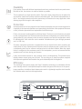
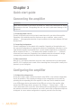
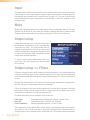
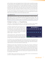
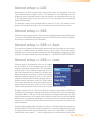
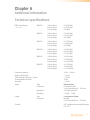
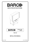
SMA & SMQ
User Manual
www.audac.eu
Index
Introduction4
Precautions7
Safety requirements7
Caution servicing7
EC Declaration of Conformity7
Waste of Electrical and Electronic Equipment (WEEE)
8
Caution8
Chapter 1: Pin connections and connectors 9
Connection standards9
Wire up the system11
Chapter 2: Front & rear panel
11
Front panel overview11
Front panel description11
Rear panel overview12
Rear panel description13
Chapter 3: Quick start guide14
Connecting the amplifier14
Configuring the amplifier14
Ready15
Chapter 4: Connecting the amplifier
16
Input connections16
Output connections16
Connection examples17
Wire up the system19
2
Chapter 5: Configuring the amplifier
20
Menu structure overview20
Main screen21
Settings menu21
Level21
Input22
Mute22
Output setup22
Filters22
Equalizing23
Delay24
Max level24
Standby24
Limiter24
Dynamic bass25
Bridge25
Clear presets25
General setup26
Input gain26
Password26
LCD27
USB27
Info28
Temperature28
Factory reset28
Save28
Lock28
Chapter 6: Additional information30
Technical specifications30
3
Introduction
WaveDynamics™ Class D power amplifiers
The SMA & SMQ series are Class D Power Amplifiers featuring WaveDynamics™ audio processing technology.
They come in different output configurations with two or four channels and are available in output powers of 350
Watt, 500 Watt and 750 Watt. Their great flexibility and different configurations make it the solution for nearly every
system, no matter if it's a fixed installation or a mobile application.
WaveDynamics™
ynamic
Bass
gital
o Filters
imiter
Speaker
Presets
7 Band
EQ
Digital
Audio Filters
A complete library of AUDAC loudspeaker and set solution presets is available for your
projects, making it easy as picking the right file, loading it & play! Besides the optimal acoustic
Energy
configurations, this library also includes the loudspeaker performance parameters providing
Efficiency
a bulletproof protection for them.
The 7-band fully parametric equalizer with adjustable frequency and Q factor and Butterworth,
Bessel and Linkwitz-Riley filters with selectable roll-off allow you to create custom
Energy
Speaker tweak
Dynamic
Speaker
configurations,
your setup
to the finest
detail and adapt to your rooms acoustics. A
Efficiency
Lockable
Protection
Bass
Presets
delay function allows time alignment of different speakers in your installation.
Configurations also allow you too bridge the outputs, doubling the output power of stereo
channels to one mono channel or make a single three-channel amplifier driving a complete
7 Band
Speakermid/high
Dynamic
Speaker
setup composed of stereo
frequency
speakersEnergy
and a bass cabinet.
EQ
Lockable
Protection
Bass
Presets
Efficiency
Controllability
t Matrix
Time
Alignment
The operation and configuration of the device can be done in multiple ways. The most
obvious way is by using the front panel controls, featuring a rotary selection dial and channel
selection buttons
clear and intuitive user
inferface
on the 2.5"
graphical Energy
LCD Display.
Digital with7aBand
Speaker
Dynamic
Speaker
Limiter
Audio Filters
EQ
Lockable
Protection
Bass
Presets
Efficiency
Total system configurations for pre-defined set solutions can be loaded into the amplifier
using the USB port.
peaker
tection
4
Dynamic
Bass
Integration of the audio system into home and industrial automation systems is made easy
through the
RS-232 connection & control port whereby functions such as input switching,
Speaker
Energy
Presets
Efficiency
volume adjustment, ... can be controlled.
Flexibility
Every system comes with different requirements and every customer has his own preferences.
Because of this, the structure is made as flexible as possible.
Input Matrix
Time
Alignment
Limiter
7 Band
EQ
Digital
Audio Filters
Lockable
Speaker
Protection
Dynamic
Bass
Speaker
Presets
Energy
Efficiency
This is achieved by an input selection matrix. Each of the input connections can be patched to
any amplifier channel and contains software controllable gain. The different implementations of
the in- and output connectors allow the easiest way of connection for every application, while
allowing signal link through to other amplifiers.
Protection
Lockable
Speaker
Protection
Firstly, user access is made possible on different levels. The device can be blocked or accessed
in user or administrator level. Different levels allow different configuration and control functions,
giving limited (Eg: only volume) control access to standard users and full configuration control
to administrators. User restriction can be enabled & disabled and is given through password
and / or USB-key.
7 Band
EQ
Lockable
Time
ignment
Limiter
Speaker
Presets
Optimal protection is not only required for the listeners satisfaction, but can also be important for
complying to
the imposed
regulations and guaranteeing the lifetime of the equipment. Because
Dynamic
Speaker
Energy
Presets precautions
Efficiency are implemented in different ways.
ofBass
this, protection
Speaker
Protection
Dynamic
Bass
Speaker
Presets
Energy
Efficiency
Secondly, equipment protection is implemented by an output limiter which monitors the
output power of every channel and will intervene when the output exceeds a certain level. The
corresponding level can be software configured and is indicated in Watts. When the output
limiter is configured at the maximum power of the loudspeaker, you can rest assured that the
speakers won't be blown during your absence.
7 Band
Digital the maximum
Lastly,
volume
EQ
Audio Filters
Lockable
for every
can be set
indepentently.
Energy This prevents users
Speakerchannel
Dynamic
Speaker
Efficiency
Protection
Bass
Presets
(having volume access) going over the limit. This can help you to keep the system compliant
with imposed regulations and maintain the good relationship with the neighbors.
Efficiency
Energy
Efficiency
The switching mode power supply and Class D Amplifier technology in combination with the
auto-standby mode for each separate amplifier channel brings an end to the era of the powerhungry amplifiers. In addition, these features also result in a lightweight amplifier which benefits
the customer when used in mobile applications.
CHANNEL 4
CHANNEL 3
CHANNEL 2
CHANNEL 1
ANALOGUE
GAIN
Input 1
Input 2
Input 3
Input 4
OFF
DSP
INPUT SELECT
ADC
ADC
DAC
Digital
Audio Filters
ADC
7 Band
EQ
Speaker
Presets
Time
Alignment
Speaker
Protection
Limiter
Dynamic
Bass
ADC
VU READ
RS232
SMA750
Prot
FUNCTION
Clip
AUDAC
-20dB
Sig
ON
POWER
CH1
CH2
Front
CPU
AMP
ADC
TEMP
ADC
Level
USB
5
6
Precautions
READ FOLLOWING INSTRUCTIONS FOR YOUR OWN SAFETY
ALWAYS KEEP THESE INSTRUCTIONS. NEVER THROW THEM AWAY
ALWAYS HANDLE THIS UNIT WITH CARE
HEED ALL WARNINGS
FOLLOW ALL INSTRUCTIONS
NEVER EXPOSE THIS EQUIPMENT TO RAIN, MOISTURE, ANY DRIPPING OR SPLASHING
LIQUID. AND NEVER PLACE AN OBJECT FILLED WITH LIQUID ON TOP OF THIS DEVICE.
DO NOT PLACE THIS UNIT IN AN ENCLOSED ENVIRONMENT SUCH AS A BOOKSHELF
OR CLOSET. ENSURE THERE IS ADEQUATE VENTILATION TO COOL THE UNIT. DO NOT
BLOCK THE VENTILATION OPENINGS.
DO NOT STICK ANY OBJECTS THROUGH THE VENTILATION OPENINGS.
DO NOT INSTALL THIS UNIT NEAR ANY HEAT SOURCES SUCH AS RADIATORS OR
OTHER APPARATUS THAT PRODUCE HEAT
DO NOT PLACE THIS UNIT IN ENVIRONMENTS WHICH CONTAIN HIGH LEVELS OF DUST,
HEAT, MOISTURE OR VIBRATION
THIS UNIT IS DEVELOPED FOR INDOOR USE ONLY. DO NOT USE IT OUTDOORS
PLACE THE UNIT ON A STABLE BASE OR MOUNT IT IN A STABLE RACK
ONLY USE ATTACHMENTS & ACCESSORIES SPECIFIED BY THE MANUFACTURER
UNPLUG THIS APPARATUS DURING LIGHTNING STORMS OR WHEN UNUSED FOR LONG
PERIODS OF TIME
ONLY CONNECT THIS UNIT TO A MAINS SOCKET OUTLET WITH PROTECTIVE
EARTHING CONNECTION
CAUTION - SERVICING
This product contains no user serviceable parts. Refer all servicing to
qualified service personnel. Do not perform any servicing (unless you
are qualified to)
EC DECLARATION OF CONFORMITY
This product conforms to all the essential requirements and further
relevant specifications described in following directives: 2004/108/EC
(EMC) and 2006/95/EC (LVD)
7
WASTE ELECTRICAL AND ELECTRONIC EQUIPMENT (WEEE)
The WEEE marking indicates that this product should not be disposed
with regular houshold waste at the end of its life cycle. This regulation
is created to prevent any possible harm to the environment or human
health.
This product is developed and manufactured with high quality materials
and components which can be recycled and/or reused. Please
dispose this product at your local collection point or recycling centre
for electrical and electronic waste. This will make sure that it will be
recycled on an environmentally friendly manner, and will help to protect
the environment in which we all live.
CAUTION
The symbols shown are internationally recognized symbols that warn about potentional
hazards of electrical products. The lightning flash with arrowpoint in an equilateral
triangle means that the unit contains dangerous voltages. The exclamation point in
an equilateral triangle indicates that it is necessary for the user to refer to the users
manual.
These symbols warn that there are no user serviceable parts inside the unit. Do not
open the unit. Do not attempt to service the unit yourself. Refer all servicing to qualified
personnel. Opening the chassis for any reason will void the manufacturer’s warranty. Do
not get the unit wet. If liquid is spilled on the unit, shut it off immediately and take it to a
dealer for service. Disconnect the unit during storms to prevent damage.
8
Chapter 1
Pin connections and connectors
CONNECTION STANDARDS
The in- and output connections for AUDAC audio equipment are performed corresponding
to international wiring standards for professional audio equipment.
XLR:
For balanced signal input connections
Pin 1: Ground
Pin 2: Signal +
Pin 3: Signal -
3-Pin Terminal Block:
For balanced signal input & link output connections.
Left: Signal - Center:Signal + Right: Ground
(XLR Pin 3)
(XLR Pin 2)
(XLR Pin 1)
9
RS232 (serial connection interface):
For connection with home automation systems, or other remote control equipment
ConnectionStandard RS232
PIN 2SMA/SMQ TX
PIN 3SMA/SMQ RX PIN 5GND
Settings
19200 Baud
8 Bit
1 Stop bit
No parity
No Handshaking
RS232
The complete command set to control the SMA/SMQ amplifiers through RS-232 is available
in the commands user manual which is freely downloadable on www.audac.eu
10
Chapter 2
Front & rear panel
Front Panel overview
SMA Series
SMQ Series
Front panel description
The front panel of all SMA/SMQ amplifiers is almost identical, with few minor differences
between the different models. The SMA series amplifiers (2-channel versions) only have
two output selection buttons, while the SMQ series amplifiers (4-channel versions) have
four. Other provided features such as USB port, LCD display and rotary selection dial are
identical for all models.
USB port
A USB port is provided on the left side of the front panel. This is meant for inserting flash
drives with configuration files to load into the amplifier or duplicating system configuration
files to the inserted medium. The inserted flash drive shall support FAT32 filesystem.
Graphical LCD display
A clear system overview and intuitive user interface is provided on the 2.5” graphical LCD
display. This true colour display provides a clear overview of the amplifiers operation mode
guaranteeing an user friendly experience when browsing through the menu structure.
11
Rotary selection dial
Browsing through the menu structure and adjusting parameters is made easy with the
rotary selection dial. This multifunctional rotatable dial allows easy one-hand operation
throughout the entire menu structure. Browsing can be done by turning it while actions
will be taken when pressing it.
Channel selection buttons with indicator LED’s
Channel selection and monitoring is made easy through a selection button together with
four indicator LED’s for every channel. When pressing the button, the menu structure will
call the settings of the corresponding channel, allowing adjustment of the parameters.
The LED’s give a continuous indication of the operation of the corresponding channel.
The green Signal LED illuminates whenever a signal is present, while the -20dB LED
illuminates when the input signal exceeds the - 20 dBu level. The Clip LED illuminates
when the corresponding channel is working at maximum level. To ensure the best signalto-noise ratio, the Clip LED may only illuminate at peak levels.
When the Clip LED illuminates, the output limiter of the amplifier will intervene avoiding
a distorted “Clipping” sound on the output. The Protection LED will illuminate when
overheating occurs, or any other fault is detected. When the protection LED is illuminated,
no signal will be available on the outputs.
Power switch
A power switch allows to switch the amplifier on and off, while the blue indicator LED
located next to the button illuminates when the power is switched on.
Rear Panel overview
SMA Series
SMQ Series
12
Rear panel description
The rear panel of all SMA/SMQ amplifiers is almost identical, with few minor differences
between the different models. The SMA series amplifiers (2-channel versions) have two
inputs and two outputs, while the SMQ series amplifiers (4-channel versions) have four.
Other provided connectivities such as RS-232 and power are identical for all models.
AC Power inlet with fuse
The mains power supply (230~240 V AC / 50 Hz) has to be applied to this AC power
inlet. The connection is made by an IEC power connector and is fitted with a fuse.
When replacing the fuse, make sure that the value of the replacement fuse matches the
value of the original fuse. (SMA350: T6.3AH/250V - SMA500: T8AH/250V - SMA750:
T12AH/250V - SMQ350: T8AH/250V - SMQ500: T12AH/250V - SMQ750: T16AH/250V)
Loudspeaker output connections
The loudspeaker output connections are implemented in two ways, using speaker output
connectors and terminal block output connectors. This way, connections can always be
made in the most simple way for every application.
A detailled description for connecting loudspeakers in the most appropriate way for each
application can be found in the next chapter ‘Connecting the amplifier’.
Signal input connections
Signal input connectors are implemented in two ways, using balanced XLR and 3-pin
terminal block connectors. This way, connections coming from the signal source such
as pre-amplifier, mixer or matrix system can always be made in the most easy and
appropriate way while allowing signal linkthrough to other amplifiers.
RS232 Connection
The amplifier can be controlled through external hardware such as home & industrial
automation systems by linking it to the RS-232 connection. The pinout and
communication settings are described in an earlier chapter of this user manual.
The complete RS-232 command instruction set and configuration information can be
downloaded from the AUDAC website.
Optional expansion port
Installation of optional modules is possible with the optional expansion slot. In standard
configuration this D-size hole is covered with a blind plate which needs to be removed
before installing the module. Information about available modules and how to install them
can be found at the AUDAC website.
13
Chapter 3
Quick start guide
Connecting the amplifier
ATTENTION
Make sure the power of the device is turned OFF before any connections or wiring
adjustments are made. Disregarding this rule can lead to permanent damage of the
equipment.
1) Connecting audio sources
Connect all the audio sources to the input connections on the rear side of the amplifier.
Depending of the installation and the used sources (pre-amplifiers, mixers, matrix
systems, ... ) the appropriate selection of input connectors can be made between XLR and
terminal block.
2) Connecting loudspeakers
Connect loudspeakers to the outputs of the amplifier. Depending of the application and
the connected loudspeakers, the appropriate selection of loudspeaker connections can be
made between speaker and terminal block. In most standard applications, loudspeakers
will be connected to the +1 / -1 terminals of the speaker connector (or + / - terminals
of terminal block connector). Depending if any channels should be connected in bridge,
corresponding connections should be made as indicated on the rear panel.
3) Other connections
After the in- and output connections are made, other connections such as mains power
(and RS-232 if required) can be made. After connecting them, the amplifier is ready to be
powered-up and configured.
Configuring the amplifier
1) Configuration using presets
In case your setup is a pre-defined set solution from AUDAC, a set solution configuration
file will be available (*.SOL) whereby all settings for the configuration can be made by
uploading the corresponding file to the amplifier. In this case, the file should be stored
on an USB storage device and inserted to the USB port on front of the amplifier. After
inserted the USB storage device, browse to the ‘Settings’ > ‘General setup’ > ‘USB’ >
‘Load’ and browse to the correct file. After selecting the corresponding file, all settings for
the selected set solution will be loaded in one action, and all other configuration steps can
be skipped. In case a custom configuration is required, proceed to the next step.
14
2) Configuring the outputs
The first step when a custom configuration is required is configuring the output channels.
In standard configuration, every output channel is functioning independently. In case
this configuration is required for your setup, this step can be skipped. When your setup
requires one (or more) bridged output channels, channel bridging settings can be made
in the ‘Settings’ > ‘Output setup’ > ‘Bridge’ menu. When the bridge function is switched
on, two channels will be merged to one output channel doubling the output power. On the
main screen, only one fader will be displayed for a bridged channel.
3) Configuring the inputs
After the output configuration has been made, the next step is the input configuration.
In standard configuration, every output channel is patched with the corresponding input
channel (Input 1 to Output 1, ... ). In case this configuration is required for your setup, this
step can be skipped. In cases where specific inputs should be assigned to the outputs,
the input selection can be made in the settings menu under ‘Settings’ > ‘Input’. Selection
is possible between all applied inputs, including summed inputs (Converting stereo inputs
to mono).
After the inputs are assigned to the outputs, the input gain for every used input should
be set. The input gain can be adjusted under ‘Settings’ > ‘General setup’ > ‘Input gain’.
On the right side of this screen are three colour indicators shown for every input, giving
feedback of the currently set gain. A correct regulation of the input gain is achieved
when the green indicator is frequently blinking, the yellow indicator is only illuminated
at the peaks (-6 dB) and the red indicator blinks rarely or not. When the red indicator
blinks frequently, the input is overdriven and the gain needs to be reduced. When the
green indicator blinks rarely or not, no input signal is detected and the gain needs to be
increased.
3) Acoustics configuration
After the in and output configurations have been made, the next step is making acoustic
configurations and optimalizations. When bass cabinets are used in the installation, it
might be required to add low-pass filters to the bass cabinets channel, and high-pass
filters to the mid/high loudspeakers channels. Filter configurations can be made in the
‘Setup’ > ‘Output configuration’ > ‘Filters’ menu. Sound quality can be optimized to
specific acoustics using a 7-band equalizer which can be found in the same menu.
Besides, other specific configurations such as limiting can be made in the same menu.
Ready
After all above connections and configurations have been made, the system is ready for
rock & roll. More specific features such as password protection, standby mode, and many
more can be configured. How this should be done can be found in further chapters of this
instruction manual.
15
Chapter 4
Connecting the Amplifier
NOTE
Make sure the power is swiched OFF when any change is made to the connections of the
amplifier.
Input connections
The signal input connections are performed using a balanced XLR and 3-pin terminal block
(3.81 mm pitch) connector for every input. Both connectors are linked in parallel, allowing
free selection to which connector the signal will be applied. If required, the second connector
can be used for linkthrough the applied signal to other amplifiers.
The input structure of the amplifier is made flexible due to the input selection matrix, meaning
that any signal applied to the amplifier can be patched to any channel. When driving multiple
channels by the same signal or summing stereo signals and converted into mono (Eg. when
the amplifier is being used in bridged mode), external links are redundant due to the input
matrix.
Selecting and assigning the input signals to the amplifier channels is made easy through
software configurable user interface which is controllable using the front panel controls.
16
Output connections
The loudspeaker output connections are performed using a speaker and 2-pin terminal
block (5.08 mm pitch) connector for every output. Both connectors are linked in parallel,
allowing free selection and the most suitable connection for every application.
The used speaker connectors are 4-pole types,
containing the output signal for the corresponding
channel on +1/-1 terminals. The speaker connector
for the first (and third for SMQ) channel also contains
the output signal for the subsequent channel on +2/-2
terminals. This allows to transfer of two amplifier
channels over one four-conductor loudspeaker cable
which is fitted with one connector. Connection in bridge
mode can also be made using one single connector
Connection examples
Normal operation mode:
This is the most common mode whereby every channel is driven with a separate signal
and a loudspeaker is connected to each of them. The loudspeakers are connected using
a two-core loudspeaker cable (or one four-core loudspeaker cable for two subsequent
channels) to the corresponding terminals (+1/-1 for speaker connectors and +/- for
terminal block connectors).
17
Bridged mono mode
In bridged mono mode, one single load is connected between two amplifier outputs,
merging both of them which results in double output power to one single load. In this
configuration, the load is connected using a two-core loudspeaker cable between the
+ terminals of both channels. When using speaker connectors, connections are made
between +1 and +2 terminals of the channel 1 (or channel 3 for SMQ). When using
terminal blocks, connections are made between both + terminals.
Selection for bridged output channels is made through software configuration by the user
interface which is controllable using the front panel controls.
Three channel configuration (Only SMQ):
In three channel configuration, two outputs are used in normal operation mode and both
other outputs are switched in bridged mode while feeding the amplifier with a stereo input
signal. This configuration is commonly used when two mid/high frequency loudspeakers
are supplemented with an additional (mono) bass cabinet for the low frequencies. The
mid/high frequency loudspeakers are connected as described in normal operation mode,
while the bass cabinet is connected as described in bridged mono mode.
Besides the selection for the bridged amplifier channel, further advanced settings such as
filtering is usually configured for this kind of setups. All these settings can be configured
by the user interface which is controllable using the front panel controls.
18
ATTENTION
Do not connect any conventional 100 Volt line transformers directly to the loudspeaker
outputs, an integrated decoupling network shall be provided when used in combination
with line transformers.
Wire up the system
The wiring of the system must be done according to the following rules, to guarantee a
proper functioning of the system in all circumstances.
1.
Speaker cable for amplified outputs:
Minimum 2 x 1.5 mm²
If distance > 15 m: 2 x 2.5 mm²
2.
Music sources and zone outputs:
Must be connected with high-quality audio cable and high-quality
connectors
19
Chapter 5
Configuring the amplifier
The configuration of the amplifier can be done using the controls on the front panel of
the amplifier. A graphical user interface is indicated on the front panel LCD display which
guarantees an intuitive and user friendly experience. The menu structure is shown in below
diagram, giving an overview of the configuration possibilities. The following pages give a
detailled explanation for every configurable function.
20
Main screen
The main screen gives a fader overview for the output
channels of the amplifier. Depending the channels for the
corresponding model (two for SMA or four for SMQ), the
output level for each channel can be adjusted.
On top of the screen, the names of the output channels
are shown (OUT 1, OUT 2, … ). Right under, the name
of the inputs (INPUT 1, INPUT 2, … ) linked with these
outputs are indicated. And below the input, the level of
the output channel is indicated.
The selection of the corresponding channel can be made
using the ‘Channel selection buttons’ which are located below the VU meters of every channel
on the front panel of the amplifier. The output level for the currently operated channel is
indicated in green and can be adjusted by turning the rotary function dial in clockwise (up)
and counter-clockwise (down) direction. The fader will slide up or down when the output
level is adjusted. The output level can be adjusted within range of 0 dB and -70 dB.
On the bottom of the this screen, a mute indicator is shown for every channel. This button
will be indicated in green when the channel is playing and turns red when muted.
Settings menu
By pressing the rotary function dial once (when the main
screen is displayed), the output settings menu will be
shown. This menu is only accessible in administrator
mode (will be described extensively in a later section of
this user manual) and allows to make adjustments to the
channel setup and general setup.
Scrolling through this menu is possible by turning the
rotary function dial. The currently selected option will be
highlighted and the possibilities will be shown on the right
side of the screen. Settings can be called by pressing the
rotary function dial. Depending of the selected setting,
a selection menu will be indicated on the right side of the display, the selected setting will
toggle between two possibilities or another selection screen will be indicated.
Level
The first selection is the adjustment of the output level for the corresponding channel. The
output level which can be selected here is identical to the output level which can be adjusted
on the main screen of the amplifier as described above. It can be adjusted within a range
of 0 dB and -70 dB. After the selection has been made, returning to the settings menu is
possible by confirming the selection through pressing the rotary function dial.
21
Input
The input which is linked to every channel can be selected in this screen. Every input signal
can be linked to every output channel, using the input selection matrix. Summed inputs for
two sequent input channels can be selected too (E.g. Input 1+2). This can be useful when
stereo input channels need to be patched to a mono output, or when the amplifier is used
in bridge mode.
Mute
Muting will completely suppress the output signal of the corresponding channel. The mute
indicator will be shown in green when the channel is playing and turns red when muted.
Toggling between both states can be done by pressing the rotary function dial once.
Output setup
Output setup will lead you to a separate menu where
the advanced configurations for the corresponding
output can be made. The output setup menu is
separately configurable for each of the outputs and
includes configuration settings which generally will
be made once for every setup / installation without
having them adjusted frequently.
To return from the output setup menu back to the
main menu, the ‘back’ option at the bottom needs
to be pressed.
Output setup >> Filters
Filters are frequently used in audio systems for different purposes. Some typical application
examples are filtering noise or other unwanted signals from an audio signal and separating
audio signals between different frequency ranges (crossover) when a 2-way (or more) system
is used.
Because the characteristics of the required filter are strongly dependent of the application,
the filter settings are made flexible and user configurable.
Filters are grouped in this menu under subdivisions ‘low pass’ and ‘high pass’, indicating
which types of filters can be configured. When a ‘Band pass’ filter is desired, this can be
achieved by a combination of a low and high pass filter.
Characteristics which can be configured for the filters are:
Filter Type: Roll-off: Cutoff frequency: Selectable between Butterworth, Bessel, Linkwitz-Riley
Selectable between 12 dB/Oct and 24 dB/Oct
Infinitely adjustable between 1 Hz and 22 kHz
The configuration of the desired filter can be made by selecting the required filter type in
the column on the left side (Low pass or High pass). Subsequently the characteristics as
described above can be adjusted on the right screen side. The currently selected parameter
22
will be indicated in green and toggling between the different values is possible by pressing
the rotary function dial. If the parameter is set to the desired value, scrolling to the next field
can be done by turning the function dial. When adjusting the frequency, a 5 digit number
is shown and the adjusting digit can be selected (turns red) and confirmed by turning and
pressing the rotary selection dial. Consecutive digits will increase when the maximum value
has been reached. After the desired frequency has been selected it can be confirmed by
pressing (turns orange) and turning the function dial clockwise to the entire right side where
the ‘OK’ word will appear. After pressing again the frequency is confirmed and the next
characteristic can be adjusted. If all characteristics are set to the required value, select the
‘BACK’ option and you will be returned to the output setup menu.
RECOMMENDATION
When separating frequency ranges in two or more way systems, a Linkwitz-Riley filter
with 24 dB / Oct roll-off is recommended between different frequency ranges. A highpass Butterworth filter with 24 dB / Oct roll-off is suggested for elemination of low
frequencies outside the frequency range of the loudspeaker, avoiding subsonic overload.
Output setup >> Equalizing
A parametric 7 bands equalizer will allow to cut or boost specific frequency ranges, helping
to improve the sound and adapt it to acoustics of the location where its being used.
A standard configuration with center frequencies for 60
Hz, 150 Hz, 400 Hz, 1 kHz, 2.6 kHz, 6.8 kHz and 15 kHz
with Q factor of 0.7 is pre-loaded. The center frequency
of each band can be infinitely adjusted within a range
of 1 Hz and 22 kHz, while the Q-factor can be adjusted
within a range of 0.1 and 15 and the level of each band
within a range of +15 dB and -15 dB.
A fader overview for the 7 bands equalizer will be shown
after selecting the ‘EQ settings’ menu item. On top of the
screen, the center frequencies for each band are shown
with right under the currently selected equalizing level.
The selection of the corresponding band can be made by turning the rotary selection dial
until the corresponding band is indicated in green and pressing it. Level adjustment can be
done by turning the selection dial and confirmed by pressing it again. After this confirmation,
another band can be selected and adjusted in identical way.
Adjustment of the Center frequencies and Q-factors can be done by selecting the
corresponding ‘EQ-frequency’ and ‘EQ Q-factor’ buttons on the bottom of the screen.
When selected, pop-up windows will appear where the corresponding adjustments for
each band can be made. Adjustment of center frequencies can be made in similar way as
described with filters above and Q-factors can changed by selecting and turning clockwise
(up) or counter-clockwise (down). This confirmation can be done by pressing again. After
the required value for each band has been set, returning to the equalizer screen can be done
by selecting the ‘BACK’ button.
The ‘BACK’ button in the left bottom corner of the equalizer screen can be selected and
pressed for returning back to the output setup menu.
23
Output setup >> Delay
This function enables to create a specific delay between the input and the output signal. This
delay can be used for time alignment between different loudspeakers in one configuration.
It is configurable in meters within a range of 0 meter and 12 meter with a resolution of 0.1
meter / step. Adjustments can be done by selecting it and turning the rotary selection dial.
After the required delay is selected, it can be confirmed by pressing the rotary function dial.
Output setup >> Max level
This function will guarantee that the output level adjustable by the fader on the main screen
(which is accessible through user level access) will never exceed a certain value as configured.
This gives protection for non-authorized persons when increasing the volume. It can be
adjusted within a range of 0 dB (no restrictions) and -70 dB.
The screen shows a fader with the configured maximum output level indicated above it.
When selected, the fader including the currently configured maximum output level will turn
green and the level is adjustable by turning the rotary function dial. The fader will slide up
or down and after the desired value has been selected, it can be confirmed by pressing the
rotary function dial.
Output setup >> Standby
When no signal is detected for a corresponding channel, it will be switched automatically to
standby mode. The delay time between the absence of a signal and switching to standby
mode can be selected in this screen. It can be disabled (never) or adjusted within a range
of 1 to 10 minutes. The power consumption will decrease when one or more channels are
switched to standby.
Output setup >> Limiter
The output level for each channel can be limited to
a certain power. This is very useful when the output
power of the amplifier is greater than the maximum
power handling of the connected loudspeaker.
Independently of a rising level of the applied input
signal, the output power will be always limited to the
set value. This way, loudspeaker damage due to power
overload can be avoided when this setting is made
correctly.
The maximum output level is indicated in Watt and is
adjustable in steps of 25 Watt (with an 8 Ohm load) to
the maximum output power of the amplifier. Adjustment of the maximum output power can
be made by turning the rotary function dial.
24
Output setup >> Dynamic bass
Dynamic bass will make a correction depending of the level (volume) in the low frequencies.
This correction will make that music will sound warm and detailed (with true reproduction
of low frequencies) at low volumes, but with increasing level (volume) the low frequencies
will be weakened. This will result in less distortion due to reduced low frequencies at high
volumes, allowing the loudspeaker to handle higher sound pressure levels with less distortion.
It can be switched ON and OFF, whereby OFF means that dynamic bass is disabled and ON
means that a level dependent correction in the low frequencies is made.
Output setup >> Bridge
Pairs of two subsequent channels can be bridged with
merged power of both channels obtaining one single
channel with double output power. The bridged pairs
should always be subsequent channels (OUT 1+OUT2
& OUT3+OUT4 for SMQ). When bridging two channels,
only one fader for the bridged channel will be shown in
the main screen.
Bridging can be switched ON and OFF, whereby OFF
means that all channels are functioning completely
separately and ON means that two channels are bridged.
For SMQ Amplifiers (four channels), three channel configurations can be made whereby two
channels are functioning separately and two channels are bridged. These configurations are
typical for applications where stereo top speakers are used in combination with a single
bass cabinet.
Output setup >> Clear presets
Loudspeaker and total system (set) configurations can be uploaded to the amplifier. Every
preset is made and optimized for one specific loudspeaker or system. This window will
indicate if any preset is currently loaded. Presets which are meant for others than the
connected loudspeakers may affect the performance and sound quality in negative way,
while not providing optimal protection.
Clearing of the currently loaded presets can be done by selecting this option and pressing
clear. Please note that other configurations for the corresponding channel (Eg. filters,
equalizing, … ) which are separately made from the preset will remain unchanged. When a
total system configuration (set solution *.SOL) is currently loaded and cleared, other channel
configurations which are part of this preset will be cleared too.
25
General setup
The general setup will lead you to a separate menu
where some global configuration settings for the
amplifier can be made. Some settings which are
accommodated under general setup are password
settings, …
To return from the output setup menu back to the
main menu, the ‘back’ option at the bottom needs to
be pressed.
General setup >> Input gain
The gain for each individual input can be set in this screen between a range of -16.5 dB
and +30.75 dB. After scrolling and selecting the right input, gain can be adjusted through
turning the rotary selection dial. Level indicators are shown on the right side of the display
indicating the correct set gain level. Three colour digits (green, yellow and red) will illuminate
at different levels and give feedback about the currently set gain. A correct regulation of the
input gain is achieved when the green indicator is frequently blinking, the yellow indicator
is only illuminated at the peaks (-6 dB) and the red indicator blinks rarely or not. When the
red indicator blinks frequently, the input is overdriven and the gain needs to be reduced.
When the green indicator blinks rarely or not, no input signal is detected and the gain needs
to be increased.
General setup >> Password
Password protection is provided in two different levels, administrator and user level.
Administrator level has full access to all available functions of the amplifier while user level
only can access the volume of the amplifier. Both passwords consist of a 4 digit code which
is intended to be different.
In standard configuration, both passwords are set to ‘0000’. In this case, full access is given
without requiring any password. If either the configured user or administrator password is
different from ‘0000’, a password will be requested before access to the relevant functions
is provided.
The configuration of the selected password can be made by selecting Admin pass or User
pass in the column on the left side. The currently selected password will be shown and the
adjusting digit can be selected (turns red) and confirmed by turning and pressing the rotary
selection dial. Consecutive digits will increase when the maximum value has been reached.
After the desired password has been selected it can be confirmed by pressing (turns red) and
turning the function dial clockwise to the entire right side where the ‘OK’ word will appear.
After pressing again the password is confirmed.
26
General setup >> LCD
Adjustment for the LCD settings can be made in this screen. The brightness of the LCD
can be adjusted within a range of 10% to 100% (standard is 80%). Adjusting of the LCD
brightness can be convenient when the device is placed in an environment with very low
or very high ambient light. Hereby the clarity of the LCD can be adjusted in such way being
clearly but unobtrusive.
The backlight off time can be adjusted within a period of 10 up to 120 minutes or never
(always on), making the backlight of the LCD automatically turn off after the set time.
General setup >> USB
USB will lead you to a separate sub-menu where all settings and options using USB functions
can be found. An USB flash disk should be inserted to the USB slot on the front of the amplifier
and shall be formatted using FAT32 filesystem.
General setup >> USB >> Save
The complete configuration of the amplifier can be saved to a file by using the ‘save’ button.
This way, a complete backup for system recovery can be made. This provides a great
advantage for re-loading a previous configuration and duplicating the configuration to other
amplifiers. The system backup will always be saved as …\AUDAC\SETTINGS\SETTINGS.SET
General setup >> USB >> Load
Different types of configuration files can be loaded
into the amplifier, such as loudspeaker presets (*.SPF),
complete set solution configurations (*.SOL) and system
backups (*.SET). Each of above configuration files have
their own filetype and will be loaded in a different way.
When pressing the load button, a window will appear
whereby browsing through the files on the inserted
medium is made possible. Browsing through folders is
possible through turning the rotary dial, lower folders
can be easily accessed by selecting them while both top
options allow to browse up or to the root of the inserted
medium. After the desired file has been found, it can be loaded by selecting it.
Speaker presets are files in *.SPF format which are prepared and provided by AUDAC and
containing all parameters for optimal performance and protection for the corresponding
loudspeaker. When a *.SPF file is loaded, the amplifier will recognize their filetype and show
a popup window wherein all channels can be selected on which this file should be applied
(whereon the corresponding loudspeaker is connected). After the selected channels are
selected, the ‘load settings’ button shall be pressed and the presets will be loaded to the
selected channels.
Complete system configurations (set solutions) are files in *.SOL format which are prepared and
provided by AUDAC. These files contain parameters for a complete configuration consisting
of multiple (with different types) loudspeakers, such as a combination of loudspeaker
cabinets with a bass cabinet, … These configuration files contain besides the protection
27
and performance parameters also information about connected channels, bridging, filtering,
etc. Additional comments about system configurations are shown on the right side of the
browse window. When a *.SOL file is selected, it will be immediately loaded without requiring
selection of the channels where it should apply to.
System backups are files in (*.SET) format which can be created by the customer themselves.
When a system backup is made using the ‘save’ action as shown above, it will be saved as
a (*.SET) file which can be re-loaded in similar way as a *.SOL file. It will be immediately
loaded without requiring channel selection where it should apply to.
General setup >> USB >> Key
An USB key with both administrator and user level access can be created when selecting
the corresponding buttons. A file containing the configured password information will be
stored to the inserted medium, providing instant access to the functions when the medium is
inserted. This will allow instant and easy access in any circumstance and will also eliminate
the possibility that someone’s peeking the password.
General setup >> Info
The info screen gives an overview of the amplifier model and the software version which it
is currently running.
General setup >> Temperature
The temperature screen indicates the current operating temperature for each individual
amplifier channel.
General setup >> Factory reset
Factory reset will recall all settings to factory defaults and all previously made settings and
configurations will be lost.
After pressing the factory reset button, a confirmation will be asked if all settings definitely
need to be reset to factory defaults. When confirmed, all settings will be lost.
Save
All currently set values for output levels, selected inputs and channel muting will be saved
when selected. After power down and restart the amplifier, these saved values will be
automatically reloaded. Other configuration settings (except output levels, inputs and muting)
are automatically saved when modified, whereby they will be automatically recalled after
power down and restart.
Lock
When selected, the amplifier will be locked and a password (when configured) will be required
before any access is given to the user interface of the amplifier.
28
Chapter 6
Additional information
Technical specifications
RMS Output Power
SMA350
4 Ohm Stereo
2 x 350 Watt
(1 kHz, THD 1%)
8 Ohm Stereo
2 x 220 Watt
8 Ohm Bridge700 Watt
SMA500
4 Ohm Stereo
2 x 500 Watt
8 Ohm Stereo2 x 300 Watt
8 Ohm Bridge1000 Watt
SMA750
4 Ohm Stereo
2 x 750 Watt
8 Ohm Stereo2 x 380 Watt
8 Ohm Bridge1500 Watt
SMQ350
4 Ohm Stereo
4 x 350 Watt
8 Ohm Stereo4 x 220 Watt
8 Ohm Bridge2 x 700 Watt
SMQ500
4 Ohm Stereo
4 x 500 Watt
8 Ohm Stereo4 x 300 Watt
8 Ohm Bridge2 x 1000 Watt
SMA750
4 Ohm Stereo
4 x 750 Watt
8 Ohm Stereo4 x 380 Watt
8 Ohm Bridge2 x 1500 Watt
Frequency response20 Hz - 20 kHz
Signal to Noise Ratio> 95 dB
Total Harmonic Distortion + Noise
< 0.05%
Common Mode Rejection70 dB
Crosstalk> 70 dB
InputsTypeBalanced Line
ConnectorsFemale XLR Input
3-pin Terminal block ~ 3.81 mm
Impedance10 k Ohm balanced
Sensitivity-30 dB ~ +5 dB
OutputTypeLoudspeaker Output
ConnectorsSpeaker
2-pin Terminal Block ~ 5.08 mm
ControlsDSP configuration through front panel
RS-232
29
IndicatorsPower
Protect
Peak
-20 dB
Signal
ProtectionDC-Short Circuit
Over Heating
Over Load
Limiter
Cooling systemTemperature controlled fan
Amplifier technologyClass-D
Power supplyTypeSwitching mode
Range230~240 V AC / 50 Hz
Power consumption
Standby
SMA350/500/750
25 Watt
SMQ350/500/750
35 Watt
IdleSMA35037 Watt
SMA50038 Watt
SMA75040 Watt
SMQ35056 Watt
SMQ50057 Watt
SMQ75060 Watt
1/8 Rated PowerSMA350145 Watt
SMA500182 Watt
SMA750262 Watt
SMQ350272 Watt
SMQ500345 Watt
SMQ750503 Watt
1/3 Rated PowerSMA350305 Watt
SMA500416 Watt
SMA750624 Watt
SMQ350592 Watt
SMQ500813 Watt
SMQ7501227 Watt
30
Notes
31
Notes
32