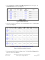
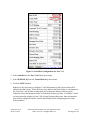
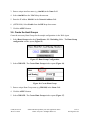
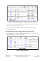
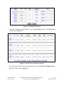
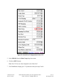
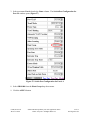
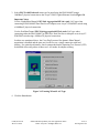
1
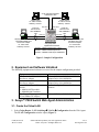
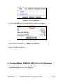
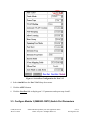
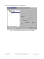
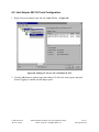
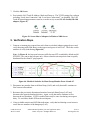
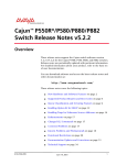
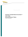
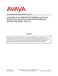
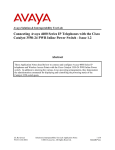
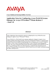
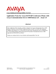
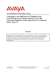
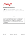
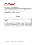
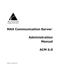
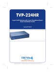
A Sample 802.1Q Hunt Group Trunk Configuration
Between an Avaya™ P882 Gigabit Ethernet Switch and
Servers with Intel Dual Port Server Adapters - Issue 1.0
Abstract
These Application Notes describe a sample Link Aggregation Group (LAG) configuration
between two Windows 2000 Servers: one equipped with an Intel PRO/100+ Dual Port Server
Adapter and the other an Intel PRO/1000MT Dual Port Server Adapter. Each adapter is
connected to an Avaya™ P882 Gigabit Ethernet switch via a separate 802.1Q Hunt Group
Trunk. A sample configuration diagram has been included along with all of the necessary
provisioning steps. These Application Notes were created as a result of field requests for
information on interoperability with Intel Dual Port Server Adapters.
GAK; Reviewed:
WCH 7/7/2003
Solution & Interoperability Test Lab Application Notes
©2003 Avaya Inc. All Rights Reserved.
1 of 31
intel-lag-notes.doc
1. Introduction
The Avaya™ P580/P882 Gigabit Ethernet Switch Hunt Group feature aggregates multiple switch
ports together, combining the bandwidth into a single connection. This feature is normally
deployed between switches to provide added bandwidth and fault tolerance. These Application
Notes describe a configuration where a hunt group is deployed between a switch and a server to
provide similar bandwidth and fault tolerance advantages. If one segment in the hunt group fails,
the remaining active members will service the failed segment traffic. The Hunt Group LoadSharing feature (enabled by default) distributes traffic load amongst the hunt group members for
improved performance. A hunt group can be configured as an 802.1Q trunk or as a clear access
link and associated with or without a router interface address.
The Avaya Hunt Group feature is a manual (or static) implementation of link aggregation. This
means the feature does not support dynamic LAG configuration or binding via some standard or
proprietary protocol. Examples of such protocols include Link Aggregation Control Protocol
(LACP) for dynamic 802.3ad and Cisco’s Port Aggregation Protocol (PAgP) for dynamic
EtherChannel negotiation. It is possible to configure Avaya Hunt Groups to interoperate with
third-party vendors. Forcing a LAG to be formed statically with a third-party vendor device
without dynamic protocol negotiation is normally used for interoperability.
Enterprise-level servers are often deployed with a dual port Network Interface Card (NIC), also
referred to as an adapter, to improve application response time and availability. Most dual port
adaptor vendors provide the option to team both ports together for link aggregation via 802.3ad,
EtherChannel or other proprietary mechanism.
These Application Notes discuss how the Avaya Hunt Group feature and load-sharing algorithm
can be combined with Intel Dual Port Server Adapters implementing either static
FastEtherChannel (FEC)/LAG or static GigabitEtherChannel(GEC)/LAG with 802.1Q enabled.
The specific Intel NIC cards validated were the Intel PRO/100+ Dual Port Server Adapter and
PRO/1000MT Dual Port Server Adapter. Figure 1 shows the sample configuration that was
verified.
GAK; Reviewed:
WCH 7/7/2003
Solution & Interoperability Test Lab Application Notes
©2003 Avaya Inc. All Rights Reserved.
2 of 31
intel-lag-notes.doc
VLAN 100 Clear Untagged
100BaseTX Links
Target Client1
IP: 100.0.0.100/24
Gateway: 100.0.0.1
Target Client2
IP: 100.0.0.101/24
Gateway: 100.0.0.1
Port 2/12
VLAN 100
802.1Q Trunk
with 1000BaseT
LAG
Port 4/4
Windows 2000 Server with
Intel PRO/1000MT Dual
Port Server Adapter
IP: 100.0.0.2/24
Gateway: 100.0.0.1
Port 4/5
Port 2/13
VLAN 100
802.1Q Trunk
with 100BaseTX
LAG
Port 3/12
Port 3/13
Avaya(TM) P882
Gigabit Ethernet Switch
Windows 2000 Server with
Intel PRO/100+ Dual
Port Server Adapter
IP: 100.0.0.3/24
Gateway: 100.0.0.1
Module 2 - M8024-100TX 24-port L2/L3
Module 3 - M8024-100TX 24-port L2/L3
Module 4 - M8008R-1000T 8-port 1000BaseT
Figure 1: Sample Configuration
2. Equipment and Software Validated
The following equipment and software were used for the sample configuration provided:
Equipment
Server with Intel PRO/100+ Dual
Port Server Adapter
Server with Intel PRO/1000MT Dual
Port Server Adapter
Avaya™ P882 Gigabit Ethernet
Switch
2 - M8024-100TX modules
1 - M8008R-1000T modules
Two Target PC’s equipped with
3Com 100BaseTX Adapters
Software
Microsoft Windows 2000 Server with Intel
Adapter Driver 6.4 with PROSet
Microsoft Windows 2000 Server with Intel
Adapter Driver 6.4 with PROSet
Version 5.4 Gigabit Ethernet Switch
Software
Microsoft Windows 2000 Professional
3. Avaya™ P882 Switch Web Agent Administration
3.1. Create the Virtual LAN
1. Select Cajun Router ! L2 Switching ! VLANs ! Configuration from the Web Agent.
The VLAN Configuration window opens (Figure 2).
GAK; Reviewed:
WCH 7/7/2003
Solution & Interoperability Test Lab Application Notes
©2003 Avaya Inc. All Rights Reserved.
3 of 31
intel-lag-notes.doc
Figure 2: VLAN Configuration
2. Click the CREATE button. The Create VLAN window opens (Figure 3).
Figure 3: Create VLAN
3. Enter a unique VLAN name (e.g. vlan100) in the Name field.
4. Enter the ID 100 in the ID field.
5. Click the APPLY button.
3.2. Configure Module 2 (M8024R-100TX) Switch Port Parameters
1. Select Cajun Router ! Modules & Ports ! Configuration from the Web Agent. The
Module Information window opens (Figure 4).
GAK; Reviewed:
WCH 7/7/2003
Solution & Interoperability Test Lab Application Notes
©2003 Avaya Inc. All Rights Reserved.
4 of 31
intel-lag-notes.doc
Figure 4: Module Information
2. Select the switch ports for the Module 2 from the Switch Ports column. The Switch Ports
window opens (Figure 5).
Figure 5: Switch Ports (reduced for brevity)
3. Select port name Port 2.12 from the Name column. The Switch Port Configuration for
Port 2.12 window opens (Figure 6).
GAK; Reviewed:
WCH 7/7/2003
Solution & Interoperability Test Lab Application Notes
©2003 Avaya Inc. All Rights Reserved.
5 of 31
intel-lag-notes.doc
Figure 6: Switch Port Configuration for Port 2.12
4. Select vlan100 from the Port VLAN drop-down menu.
5. Click the APPLY button.
6. Click the Next Port link to display port 2.13 parameters and repeat steps 4 and 5.
3.3. Configure Module 3 (M8024R-100TX) Switch Port Parameters
GAK; Reviewed:
WCH 7/7/2003
Solution & Interoperability Test Lab Application Notes
©2003 Avaya Inc. All Rights Reserved.
6 of 31
intel-lag-notes.doc
1. Select Cajun Router ! Modules & Ports ! Configuration from the Web Agent. The
Module Information window opens (Figure 7).
Figure 7: Module Information
2. Select the switch ports for the Module 3 from the Switch Ports column. The Switch Ports
window opens (Figure 8).
Figure 8: Switch Ports (reduced for brevity)
3. Select port name Port 3.12 under the Name column. The Switch Port Configuration for
Port 3.12 window opens (Figure 9).
GAK; Reviewed:
WCH 7/7/2003
Solution & Interoperability Test Lab Application Notes
©2003 Avaya Inc. All Rights Reserved.
7 of 31
intel-lag-notes.doc
Figure 9: Switch Port Configuration for Port 3.12
4. Select vlan100 from the Port VLAN drop-down menu.
5. Select IEEE 802.1Q from the Trunk Mode drop-down menu.
6. Click the APPLY button.
Notes: It is only necessary to configure VLAN information for the first port that will be
added to the Hunt Group. When the first port is added to the Hunt Group, it is designated as
the “Base Port” and all other member ports will assume the identity of the base port.
Unknown unicast and broadcast traffic is flooded on the base port only. If multiple VLANs
are being statically mapped (via the CLI) to Hunt Group member ports, then each member
port must be configured with the VLANs individually before configuring them as Hunt
Group members.
GAK; Reviewed:
WCH 7/7/2003
Solution & Interoperability Test Lab Application Notes
©2003 Avaya Inc. All Rights Reserved.
8 of 31
intel-lag-notes.doc
3.4. Configure Module 4 (M8008R-1000T) Switch Port Parameters
1. Select Cajun Router ! Modules & Ports ! Configuration from the Web Agent. The
Module Information window opens (Figure 10).
Figure 10: Module Information
2. Select the switch ports for the Module 4 from the Switch Ports column. The Switch Ports
window opens (Figure 11).
Figure 11: Switch Ports (reduced for brevity)
GAK; Reviewed:
WCH 7/7/2003
Solution & Interoperability Test Lab Application Notes
©2003 Avaya Inc. All Rights Reserved.
9 of 31
intel-lag-notes.doc
3. Select port name Port 4.4 under the Name column. The Switch Port Configuration for
Port 4.4 window opens (Figure 12).
Figure 12: Switch Port Configuration for Port 4.4
4. Select vlan100 from the Port VLAN drop-down menu.
5. Select IEEE 802.1Q from the Trunk Mode drop-down menu.
6. Click the APPLY button.
Notes: Configure the first port in the Hunt Group with VLAN information. The first port
will be added to the Hunt Group and is designated as the “Base/Root Port”. All other ports
will assume the identity of the base port.
GAK; Reviewed:
WCH 7/7/2003
Solution & Interoperability Test Lab Application Notes
©2003 Avaya Inc. All Rights Reserved.
10 of 31
intel-lag-notes.doc
3.5. Create and Assign an IP Interface to the VLAN
1. Select Interfaces under the Cajun Router ! Routing ! IP ! Configuration folder. The
IP Interfaces window opens (Figure 13).
Figure 13: IP Interfaces
2. Click the CREATE button. The Add IP Interface window opens (Figure 14).
Figure 14: Add IP Interface
GAK; Reviewed:
WCH 7/7/2003
Solution & Interoperability Test Lab Application Notes
©2003 Avaya Inc. All Rights Reserved.
11 of 31
intel-lag-notes.doc
3. Enter a unique interface name (e.g vlan100) in the Name field.
4. Select vlan100 from the VLAN drop-down menu.
5. Enter the IP address 100.0.0.1 in the Network Address field.
6. (OPTIONAL) Select Enable from the RIP drop-down menu.
7. Click the APPLY button.
3.6. Create the Hunt Groups
Create the necessary Hunt Groups for the sample configuration via the Web Agent.
1. Select Hunt Groups under the Cajun Router ! L2 Switching folder. The Hunt Group
configuration window opens (Figure 15).
Figure 15: Hunt Group Configuration
2. Select CREATE. The Create Hunt Group window opens (Figure 16).
Figure 16: Create Hunt Group
3. Enter a unique Hunt Group name (e.g PRO100) in the Name field.
4. Click the APPLY button.
5. Select CREATE. The Create Hunt Group window opens (Figure 17).
GAK; Reviewed:
WCH 7/7/2003
Solution & Interoperability Test Lab Application Notes
©2003 Avaya Inc. All Rights Reserved.
12 of 31
intel-lag-notes.doc
Figure 17: Create Hunt Group
6. Enter a unique Hunt Group name (e.g PRO1000) in the Name field.
7. Click the APPLY button.
3.7. Disable Module 3 Ports Being Added to the Hunt Group
1. Select Cajun Router ! Modules & Ports ! Configuration from the Web Agent. The
Module Information window opens (Figure 18).
Figure 18: Module Information
2. Select the switch ports for Module 3 from the Ports column. The Physical Port
Configuration – Module 3 window opens (Figure 19).
GAK; Reviewed:
WCH 7/7/2003
Solution & Interoperability Test Lab Application Notes
©2003 Avaya Inc. All Rights Reserved.
13 of 31
intel-lag-notes.doc
Figure 19: Physical Port Configuration – Module 3 (reduced for brevity)
3. Uncheck the checkboxes from the Enable column for Port 3.12 and Port 3.13 to disable
each prior to adding them to a Hunt Group.
Note: Ports must be disabled before being added to the Hunt Group as member ports.
4. Click the APPLY button.
3.8. Disable Module 4 Ports Being Added to the Hunt Group
1. Select Cajun Router ! Modules & Ports ! Configuration from the Web Agent. The
Module Information window opens (Figure 20).
Figure 20: Module Information
GAK; Reviewed:
WCH 7/7/2003
Solution & Interoperability Test Lab Application Notes
©2003 Avaya Inc. All Rights Reserved.
14 of 31
intel-lag-notes.doc
2. Select the switch ports for Module 4 from the Ports column. The Physical Port
Configuration – Module 4 window opens (Figure 21).
Figure 21: Physical Port Configuration – Module 4
3. Uncheck the checkboxes from the Enable column for Port 4.4 and Port 4.5 to disable each
prior to adding them to the Hunt Group.
4. Click the APPLY button.
3.9. Add Module 3 Ports to the Hunt Group
1. Select Cajun Router ! Modules & Ports ! Configuration from the Web Agent. The
Module Information window opens (Figure 22).
GAK; Reviewed:
WCH 7/7/2003
Solution & Interoperability Test Lab Application Notes
©2003 Avaya Inc. All Rights Reserved.
15 of 31
intel-lag-notes.doc
Figure 22: Module Information
2. Select the switch ports for the Module 3 from the Switch Ports column. The Switch Ports
window opens (Figure 23).
Figure 23: Switch Ports (reduced for brevity)
3. Select port name Port 3.12 under the Name column. The Switch Port Configuration for
Port 3.12 window opens (Figure 24).
GAK; Reviewed:
WCH 7/7/2003
Solution & Interoperability Test Lab Application Notes
©2003 Avaya Inc. All Rights Reserved.
16 of 31
intel-lag-notes.doc
Figure 24: Switch Port Configuration for Port 3.12
5. Select PRO100 from the Hunt Group drop-down menu.
6. Click the APPLY button.
Note: Port 3/12 has now been designated as the “Base Port”.
7. Click Next Port to display port 3.13 parameters and repeat steps 5 and 6.
GAK; Reviewed:
WCH 7/7/2003
Solution & Interoperability Test Lab Application Notes
©2003 Avaya Inc. All Rights Reserved.
17 of 31
intel-lag-notes.doc
3.10. Add Module 3 Ports to the Hunt Group
1. Select Cajun Router ! Modules & Ports ! Configuration from the Web Agent. The
Module Information window opens (Figure 25).
Figure 25: Module Information
2. Select the switch ports for the Module 4 from the Switch Ports column. The Switch Ports
window opens (Figure 26).
Figure 26: Switch Ports (reduced for brevity)
GAK; Reviewed:
WCH 7/7/2003
Solution & Interoperability Test Lab Application Notes
©2003 Avaya Inc. All Rights Reserved.
18 of 31
intel-lag-notes.doc
3. Select port name Port 4.4 under the Name column. The Switch Port Configuration for
Port 4.4 window opens (Figure 27).
Figure 27: Switch Port Configuration for Port 4.4
8. Select PRO1000 from the Hunt Group drop-down menu.
9. Click the APPLY button.
GAK; Reviewed:
WCH 7/7/2003
Solution & Interoperability Test Lab Application Notes
©2003 Avaya Inc. All Rights Reserved.
19 of 31
intel-lag-notes.doc
3.11. Enable the Module 3 Hunt Group Member Ports
1. Select Cajun Router ! Modules & Ports ! Configuration from the Web Agent. The
Module Information window opens (Figure 28).
Figure 28: Module Information
2. Select the switch ports for Module 3 from the Ports column. The Physical Port
Configuration – Module 3 window opens (Figure 29).
Note: The Figure 31 image has been reduced for brevity.
Figure 29: Physical Port Configuration – Module 3 (reduced for brevity)
3. Check the checkboxes from the Enable column for Port 3.12 and Port 3.13 to enable each
Hunt Group member port.
4. Click the APPLY button.
GAK; Reviewed:
WCH 7/7/2003
Solution & Interoperability Test Lab Application Notes
©2003 Avaya Inc. All Rights Reserved.
20 of 31
intel-lag-notes.doc
3.12. Enable the Module 4 Hunt Group Member Ports
1. Select Cajun Router ! Modules & Ports ! Configuration from the Web Agent. The
Module Information window opens (Figure 30).
Figure 30: Module Information
2. Select the switch ports for Module 4 from the Ports column. The Physical Port
Configuration – Module 4 window opens (Figure 31).
Figure 31: Physical Port Configuration – Module 4 Window
3. Check the checkboxes from the Enable column for Port 4.4 and Port 4.5 to enable each
Hunt Group member port.
4. Click the APPLY button.
GAK; Reviewed:
WCH 7/7/2003
Solution & Interoperability Test Lab Application Notes
©2003 Avaya Inc. All Rights Reserved.
21 of 31
intel-lag-notes.doc
4. Intel PRO/1000MT Dual Port Server Adapter Configuration
For brevity, the configuration for the PRO/100+ is not discussed. The configuration for both
adapters is identical with the exception of interface IP address and LAG mechanism.
4.1. Creating an Intel Link Aggregation Adapter Team
1. Launch the Intel PROSet II application from Windows (Figure 32).
Figure 32: Intel PROSet II Graphical User Interface
2. Right click on either of the two adapters and select Add to Team ! Create New Team …
to create a new Link Aggregation adapter team (Figure 33).
Figure 33: Navigating to Create New Adapter Team
GAK; Reviewed:
WCH 7/7/2003
Solution & Interoperability Test Lab Application Notes
©2003 Avaya Inc. All Rights Reserved.
22 of 31
intel-lag-notes.doc
3. Select GEC/LA/802.1ad:static team type for interfacing the PRO/1000MT using a
1000BaseT physical connection to the Avaya™ P882 Gigabit Ethernet Switch (Figure 34).
Important Notes:
Use the GigabitEtherChannel GEC/Link Aggregation/802.3ad: static LAG type when
connecting a PRO/1000MT Dual Port Server Adapter to an Avaya™ P580/P882 switch using
a 1000BaseT physical connection.
Use the FastEtherChannel FEC/Link Aggregation/802.3ad: static LAG type when
connecting either the PRO/1000MT or PRO/100+ Dual Port Server Adapters to an Avaya™
P580/P882 switch using a 100BaseTX physical connection.
In either case mentioned above, the Cisco PAgP protocol for dynamic EtherChannel
negotiation is disabled and the ports are forced to act as a single connection with load
sharing. For optimal performance, Intel recommends that the Spanning Tree Protocol (STP)
be disabled when using either of these two LAG modes for adapter teaming.
Figure 34: Teaming Wizard LAG Type
4. Click the Next button.
GAK; Reviewed:
WCH 7/7/2003
Solution & Interoperability Test Lab Application Notes
©2003 Avaya Inc. All Rights Reserved.
23 of 31
intel-lag-notes.doc
5. Click the Next button to bypass the Teaming Wizard notification regarding multiple team
memberships (Figure 35).
Figure 35: Teaming Wizard Notification
6. Click the Next button to bypass the Teaming wizard WARNING regarding team connection
to GEC/Link Aggregation-capable switch (Figure 36).
Figure 36: Teaming Wizard WARNING
GAK; Reviewed:
WCH 7/7/2003
Solution & Interoperability Test Lab Application Notes
©2003 Avaya Inc. All Rights Reserved.
24 of 31
intel-lag-notes.doc
7. Click the checkbox on the second adapter to add it in the team configuration (Figure 37).
Figure 37: Teaming Wizard Membership Selection Popup
8. Click the Next button.
9. Click the Next button to complete the adapter team configuration (Figure 38).
Figure 38: Teaming Wizard Finish Configuration Popup
GAK; Reviewed:
WCH 7/7/2003
Solution & Interoperability Test Lab Application Notes
©2003 Avaya Inc. All Rights Reserved.
25 of 31
intel-lag-notes.doc
10. Observe that the adapter team was created (Figure 39).
Figure 39: PROSet II with GEC/LA/802.3ad:static Mode Team #0
GAK; Reviewed:
WCH 7/7/2003
Solution & Interoperability Test Lab Application Notes
©2003 Avaya Inc. All Rights Reserved.
26 of 31
intel-lag-notes.doc
4.2. Intel Adapter 802.1Q Trunk Configuration
1. Right click on the adapter team and select Add VLAN …(Figure 40).
Figure 40: Adding VLAN to LAG via PROSet II GUI
2. Click the OK button to acknowledge that adding a VLAN to the team requires that QoS
Packet Tagging be enabled on both adapter ports.
GAK; Reviewed:
WCH 7/7/2003
Solution & Interoperability Test Lab Application Notes
©2003 Avaya Inc. All Rights Reserved.
27 of 31
intel-lag-notes.doc
3. Enter the ID 100 in the VLAN ID field of the Add New VLAN popup window (Figure 41).
Figure 41: Add New VLAN Popup
4. Enter the name vlan100 in the Name field.
5. Click the OK button to complete the VLAN binding.
6. Observe that the adapter team has binding with VLAN 100 (Figure 42).
Figure 42: Adapter Team with VLAN 100 Binding
GAK; Reviewed:
WCH 7/7/2003
Solution & Interoperability Test Lab Application Notes
©2003 Avaya Inc. All Rights Reserved.
28 of 31
intel-lag-notes.doc
7. Click the OK button.
8. Provision the LAG Trunk IP Address, Mask and Gateway. The TCP/IP settings for each port
including “Local Area Connection” and “Local Area Connection 2” are disabled. The LAG
Trunk IP networking parameters must be set on the newly created VLAN vlan100, ID: 100
adapter (Figure 43).
Figure 43: Screen Shot of Adapters in Windows 2000 Server
5. Verification Steps
1. Generate a constant ping request from each client to each Intel adapter equipped server and
verify that ping traffic load shares on the ingress and egress of each LAG. Check the switch
statistics to verify load sharing (Figure 44).
Note: In Figure 44, the base port has more traffic because STP is enabled by default and all
STP PDU’s are sent on the base port only. Observe that the unicast packet count is equally
distributed for the client PC ping requests.
Figure 44: Module 4 Statistics for Hunt Group Member Ports 4/4 and 4/5
2. Disconnect one member from each Hunt Group (LAG) and verify that traffic continues to
flow between all machines.
3. Reconnect the previously disconnected member from each Hunt Group (LAG) and
disconnect the opposite member this time. Again, verify that traffic continues to flow
between the two machines. If STP is enabled, there may be some loss during convergence
delay. To avoid this, disable STP on the switch ports.
4. Using available statistics and LED link indications, verify that load sharing occurs between
across the two members of the huntgroup (LAG).
GAK; Reviewed:
WCH 7/7/2003
Solution & Interoperability Test Lab Application Notes
©2003 Avaya Inc. All Rights Reserved.
29 of 31
intel-lag-notes.doc
6. Conclusion
Connectivity between an Avaya™ P882 Gigabit Ethernet switch using Hunt Groups with 802.1Q
tagging to Intel PRO/100+ and PRO1000/MT Dual Port Server Adapters can be achieved by
following the guidelines demonstrated in these Application Notes.
7. Additional References
The following reference documents can be obtained online at the Avaya Support website:
• Avaya P550R, P580, P880 and P882 MultiService Switch User Guide
Other helpful reference documents available from Intel include the following:
• Intel Dual Port Server Adapter User Documentation
GAK; Reviewed:
WCH 7/7/2003
Solution & Interoperability Test Lab Application Notes
©2003 Avaya Inc. All Rights Reserved.
30 of 31
intel-lag-notes.doc
©2003
Avaya Inc. All Rights Reserved.
Avaya and the Avaya Logo are trademarks of Avaya Inc. All trademarks identified by ® and ™
are registered trademarks or trademarks, respectively, of Avaya Inc. All other trademarks are the
property of their respective owners. The information provided in these Application Notes is
subject to change without notice. The configurations, technical data, and recommendations
provided in these Application Notes are believed to be accurate and dependable, but are
presented without express or implied warranty. Users are responsible for their application of any
products specified in these Application Notes.
Please e-mail any questions or comments pertaining to these Application Notes along with the
full title name and filename, located in the lower right corner, directly to the Avaya Solution &
Interoperability Test Lab at [email protected]
GAK; Reviewed:
WCH 7/7/2003
Solution & Interoperability Test Lab Application Notes
©2003 Avaya Inc. All Rights Reserved.
31 of 31
intel-lag-notes.doc