1
IC600 Reference and operators manual
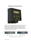
The IC600 and IC600 'plus' are Position display unit's that can be retro-fitted
to almost any machine as long as a Quadrature encoder can be fitted. They
are fully programmable and can display Millimetre’s, Centimetres, inches or
fractal inches or a combination of units i.e. millimetre’s and inches at the
same time.
IC600 Dimensions
IC600 Display visible
IC600 in mm mode
188 mm x 102 mm x 33 mm
122 mm x 22 mm
IC600 in Dual mode
Screens shown are above are 60% full size
Contents
Contents
1
A quick tour of the IC600
Display
Keypad
2
3
Power up and self test
4
Simple
Simple screen's
Advanced
Modifying parameters
5
6
7
8
Operation
Configuration
Parameter explanation's
9 - 10
Installation
11
IC600 wiring
12
Specifications
13
Setup information
14
Trouble shooting
15
Manufacturers information
16
2
A quick tour of the IC600
The IC600 Display
The IC600 display is a 2 line by 20 character LCD Display, this enables us
to display both numbers and text, which makes installation and operation of
the IC600 both quick and easy.
The IC600 Keypad
The IC600 keypad has been kept to a minimum to ease learning, this enables
the operator to feel at ease with the unit very quickly. The keypad consists of
just 3 buttons;
This button allows the operator to change the measuring
unit in use i.e. MM, CM, IN
This button is used after power up to calibrate the IC600
and to ENTER values during installation.
This button allows a change in the number of decimal places
displayed it also allows the operator to re calibrate the IC600
if required.
3
OPERATION
After power up the IC600 will self test to confirm that all the parameters
are correct and display "OK"
The display will now show the version of firmware,
This is followed by the Suppliers logo screen,
The display will now change to the operating screen, this screen will vary
depending upon the model of 600 that you have.
If you are using the "IC600" the screen will prompt you to move to a
position and press SET
If you are using the "IC600 PLUS" the screen will display the current
position (this is the position at power off assuming the gauge has not moved)
4
CONFIGURATION
There are 2-configuration menu's used to setup the IC600, Simple and
Advanced
1) SIMPLE CONFIGURATION
The "SIMPLE CONFIGURATION" mode is accessed by pressing and
holding the "SET" button from the Firmware screen until "SIMPLE
CONFIG" is displayed.
SIMPLE CONFIGURATION
Parameter
Options
Reverse encoder
Encoder PPR
Pitch
Default units
Save changes
Yes / No
1 - 1000
1 - 100
mm/cm/in
Yes / No
Default
No
100
10 mm
mm
Yes
5
SIMPLE CONFIGURATION SCREENS
This page shows all the screen's used within the Simple configuration from
entry into Simple configuration to saving and exiting the routines, to change
any value simply turn the encoder until the required value is displayed then
press "SET" to store the value and step onto the next parameter
6
2) ADVANCED CONFIGURATION
The "ADVANCED CONFIGURATION " is be accessed by pressing and
holding the "UNIT" and "MODE" buttons from the Firmware screen until
"ADVANCED CONFIG" is displayed.
ADVANCED CONFIGURATION
Parameter
Reverse encoder
Encoder PPR
Pitch
Default units
Enable mm
Precision mm(decimal places)
Enable cm
Precision cm
Enable inches
Precision IN
Enable Fractal inches
Precision fractal
Enable dual display
Enable pulses
Dual unit (top line)
Dual unit (bottom line)
Metric start position
Imperial start position
Show speed bar
Show max speed
Save changes
Options
Yes / No
1 to 1000
1 to 100
mm
Yes / No
0,1,2
Yes / No
0,1,2,3
Yes / No
0,1,2,3
Yes / No
1/4 to 1/64ths
Yes / No
Yes / No
mm/cm/in
mm/cm/in
1 to 500
1 to 36
Yes / No
Yes / No
Yes / No
Default
NO
100
10
mm
Yes
2
Yes
3
Yes
3
Yes
1/64ths
Yes
No
mm
in
100
4 in
Yes
No
Yes
7
MODIFYING PARAMETERS
To change the value of any parameter within "SIMPLE" or "ADVANCED"
configuration modes the encoder must be turned either clockwise or
Anti-clockwise, turning the encoder will either increment or decrement the
selected parameter.
To accept and enter a value the "SET" button is used, each time the "SET"
button is pressed the current (on screen) value is accepted and the IC600
moves onto the next parameter.
If required the IC600 can be pre-programmed from the factory to reduce the
time required to install the unit, however if any gearing is to be used we
would strongly recommend that the Pitch is adjusted to allow for any
effective gearing
8
PARAMETER EXPLANATION'S
Reverse encoder
If you find that the display counts the wrong way, up instead of down this
parameter may be used. The output from the encoder could be swapped over
(A,B/B,A) but obviously it is much easier to swap it in software.
Encoder PPR
This is the number of Pulses Per Revolution of the encoder.
Pitch
This refers to the pitch of the leadscrew on the machine this can be
manipulated if any gearing is used during the installation.
Default units
When the IC600 powers up the units specified in this parameter will be used
if Default units are set to inches the IC600 will power up in inches
regardless of the units at switch off.
Enable mm - cm - in - 1/64ths
This option allows the user to enable the units that can be selected with the
mode button any units that are NOT enabled will not be seen when mode is
used
Precision
This parameter allows you to select the number of decimal places for the
individual units (mm, cm, in, 1/64ths) the maximum value is 3 decimal places
the minimum is 0 decimal places
Enable Dual display
This parameter allows the IC600 to display two units of measurement the
units as selected by Dual unit (top line) and Dual unit (bottom line)
9
Enable pulses
This parameter is only used for installation purposes, pulses can't be easily
used as a unit of measurement, you can however use this function to tell you
how many pulses per revolution your encoder is if for any reason it is not
known.
Start position
When the IC600 powers up it will display "position to XXX and press set"
Where XXX is the start position, the default for this is 100 mm or 4 inches.
The start position can be anywhere throughout the travel of the backgauge. If
you want to start towards the rear of the machine simply change the start
position to a convenient number i.e. 500mm.
NOTE
The IC600 'plus' will not display "position to XXX" at power up it will
display the current position.
Show speed
This parameter can be useful for providing a visual indication that the
backgauge is moving it appears as a bar display on the right-hand side of the
display.
Show Max speed
The max speed is a permanent bar on the left-hand side of the display; it
should only be used at the time of installation to show the maximum speed
achieved by the backgauge. If for any reason the bar reaches the top of the
display it is recommended that the encoder be geared typically a 2:1
reduction would be used.
Save changes
If you have edited or changed any parameter and wish to keep the changes
you should select "YES" if you select "NO" all the changes will be lost.
10
INSTALLATION
Installation of the IC600 is very easy and straight forward, we do however
recommend that you use a reputable company this will ensure your safety as
the end user and also give trouble free operation.
IC600
Supply
97 to 240 v ac
Interconnection unit
Power
Supply
DC from supply
Encoder
Flexible coupling
Leadscrew
11
IC600 WIRING
The IC600 wiring is simple and can be accomplished in a matter of minutes.
The lead from the IC600 is terminated with an RJ45 connector this plug's
into the interconnection unit, the DC output from the power supply is then
connected to the +12v input and Common terminals respectively.
The encoder, if you are using a British encoder the connections are as
follows.
Enc + 12v…………..White
Common……………Black
Quad A……………..Brown
Quad B……………..Red
The screen should also be connected to the Common terminal within the
interconnection unit.
DC SUPPLY
If the power supply was supplied as part of the IC600 kit the terminations
will have been made and tested at the factory.
Common………….BLACK
12v Input………….BLACK + RED TIP
Once the IC600 is installed and configured it will require an initial datum,
the default is 100mm (set in Advanced Config) simply move the backgauge
forward to 100mm and press SET the display should now agree with the
actual position of the backgauge.
12
SPECIFICATION
IC600
DC input
Current consumption
Max Quadrature speed
Max size displayed
2 X 20 LCD display
Display resolution
Firmware
IC600
IC600 'plus'
10 - 18 V
250 mA (with Encoder)
>50 kHz *
> +/- 14800 mm
> +/- 8450 Inches
8 mm characters
0.01 mm **
Ver 1.70 - MR
Ver 1.80 - MR
Power supply (if supplied in kit)
AC input voltage
Overload protection
DC output
Max current
97 - 270 V
Pulsing mode auto recovery
12 Volts +/- 5%
1.2 A
Encoder (if supplied in kit)
Type
Model
Voltage
PPR
Shaft
British encoder
758 - HV
5 - 24 V DC
100 or 360
10 mm Dia
NOTE
* Max speed equates to 1.25 m/s with a 10mm pitch leadscrew
** Display resolution may vary depending upon pitch and gearing
13
SETUP INFORMATION
Setup information is given and should only be used in the unlikely event that
the setup held within the IC600 becomes corrupt. This sheet should be
completed at the time of installation by the Engineer or installer.
ADVANCED CONFIG
Parameter
Your Settings
Reverse encoder
Encoder PPR
Pitch
Default units
Enable mm
Precision mm (decimal places)
Enable cm
Precision cm
Enable inches
Precision IN
Enable Fractal inches
Precision fractal
Enable dual display
Enable pulses
Dual unit (top line)
Dual unit (bottom line)
Metric start position
Imperial start position
Show speed bar
Show max speed
14
TROUBLE SHOOTING
IC600 dead
Check that you have 12 volts at the
interconnection unit (+V and Common)
Check all leads for damage
IC600 beeps and resets for
no reason
Check the PSU it could be shutting down on
over current or under voltage on the mains
side or due to excessive noise on the supply
IC600 displays keystuck
100 or 010 or 001
The 100 indicates that the first switch is
stuck the 010 for the second switch and
001 for third switch (first switch being units)
IC600 Inaccurate
If the error is consistent check the
PPR and Pitch in setup and adjust to correct
If the error is not consistent check for loose
or slipping couplings also check for loose
wires in the interconnection unit, a poor
supply can also cause this problem
IC600 won't display
Required "UNITS"
Check the advanced setup to see if the units
are enabled
IC600 has a * on the right
Hand side of display
This advises the user that the count rate is
almost at it's maximum rate and may require
gearing down of the encoder.
IC600 won't go into prog
mode (Advanced or simple)
To access Advanced or simple Config. the
correct buttons must be pressed + held while
the display shows "FIRMWARE" screen
See Page 5 and Page 6.
15
This product has been designed and manufactured to the highest standards
by SP Electronics (Tarleton) for information on other products and services
please contact the sales and support office on :Tel
Fax
Email
0870 321 5116
0870 321 5118
[email protected]
If you have any technical queries about this product please contact the
technical support office on :Tel
Fax
Email
0870 321 5117
0870 321 5119
[email protected]
SP Electronics (Tarleton) cannot be held liable for any damage, loss or injuries as a result of improper or
incorrect use of our equipment. Nor can we be held liable for any damage, loss or injury as a result of poor
or improper installation carried out by any third party.
If you have any reservations you should contact us in writing stating the nature of your concern this will
enable us to look into it more deeply.
Every effort has been made to ensure correct operation of this equipment if you as a customer find anything
that you consider to be incorrect please advise us we can then endeavour to correct it.
Due to ongoing development we reserve the right to change specification without prior notice
Warranty is on a "return to us basis" unless otherwise agreed in writing our policy is to return goods within
3 working days or sooner, SP Electronics does not accept any liability for loss of production or output in
the unlikely event of equipment failure.
16