1
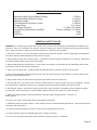
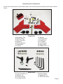
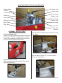
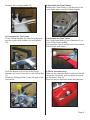
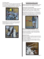
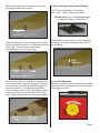
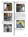
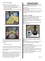
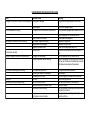
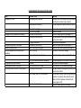
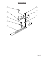
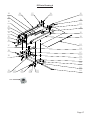
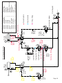
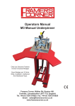
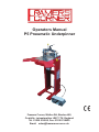
Operators Manual
P5 Pneumatic Underpinner
Framers Corner, Walker Rd, Bardon Hill,
Coalville, Leicestershire LE67 1TU, England
Tel. 01530 516925, Fax. 01530 516929
Email: [email protected]
P5 Technical Specification
Moulding Width (Using Rebate Clamp)
Moulding Width (Without Clamp)
Moulding Height
Pin Placement from Back Corner
Wedge Sizes
Air Supply Pressure
Underpinner Dimensions (WxDxH)
Weight
Warranty
0-70mm
0-110mm
0-100mm
0-120mm
5 to 15mm
6 - 8bar (90-115psi)
730mm x 800mm x 1110mm
60kg
1 year
GENERAL SAFETY RULES
WARNING: Do not attempt to operate the machine until you have read thoroughly and understood completely all instructions, rules, etc. contained in this manual. Failure to comply may result in accidents involving serious personal
injury. Keep this owner's manual and review frequently for continuous safe operation.
1. Know your machine. For your own safety, read the owner's manual carefully. Learn its application and limitations,
as well as specific potential hazards pertinent to this machine.
2. Keep guards in place and in working order. If a guard must be removed for maintenance or cleaning, make sure it
is properly replaced before using the machine again.
3. Remove adjusting keys and spanners. Form a habit of checking to see that the keys and adjusting spanners are
removed from the machine before operating it.
4. Keep your work area clean. Cluttered areas and workbenches increase the chance of an accident.
5. Do not use in dangerous environments. Do not use power tools in damp or wet locations, or expose them to rain.
Keep work areas well illuminated.
6. Keep children away. All visitors should be kept a safe distance from the work area.
7. Use the right tools. Do not force the machine or attachments to do a job for which they are not designed. Contact
the manufacturer or distributor if there is any question about the machine's suitability for a particular job.
8. Wear proper apparel. Avoid loose clothing, gloves, ties, rings, bracelets, and jewellery which could get caught in
moving parts. Non-slip footwear is recommended. Wear protective hair covering to contain long hair.
9. Always use safety glasses. Normal spectacles only have impact resistant lenses. They are not
safety glasses.
10. Do not over-reach. Keep proper footing and balance at all times.
11. Maintain machine in good condition. Keep machine clean for best and safest performance. Follow instructions for
lubrication and maintenance.
12. Disconnect the machine from power or source (or air supply) before servicing.
13. Never leave the machine unattended with the air supply connected.
14. Do not use any power tools while under the effects of drugs, alcohol or medication.
Page 2
Unpacking Your Underpinner
Check the contents have arrived safely and all the components are present according to the list
below.
A
B
C D
I
G
E
F
H
K
J
M
L
N
Large Parts
A) Accessory Tray
B) Safety Guard
C) Front Stop Bar
D) Spanner
E) Clamp Adjuster
F) Vertical Bar
G) Handle
H) Washer
I) L Shaped Pad
J) Round Pad
K) Left Table
L) Front Clamp
M) Right Table
N) Rubber Feet x 4
O
P
Q
R
U
S
T
Small Parts
O) Cap Head Bolt x 8
P) Washer x 8
Q) Locking Collar
R) Locking Handle
S) Brass Nipple
T) Magentic Tool
U) Set of Hex Keys
Page 3
MAIN FEATURES OF THE P5 UNDERPINNER
Clamp Height
Adjuster
Top Clamp Lock
Fence Lock
Top Clamp Pad
Front Wedge
Position Lock
Guard
Front Clamp
Sliding Fence
Main Table
Side Table
Rear Wedge
Position Lock
Magazine Feeder
Anchor Bolt
Wedge Size
Selector
ASSEMBLY INSTRUCTIONS
1) Fit the Rubber Feet
Screw 4 feet (N) into threaded holes in the base
of the stand. The feet are adjustable in height.
Use a 13mm spanner to tighten the locking nut,
once the machine has been levelled.
Insert the Front Stop Bar (C) into the hole in the
fence block.
Place the Brass Nipple (S) into the threaded
hole in the fence block.
2) Assemble the Fence
Fit the Handle and Locking Collar (Q) over the
right hand fence bar.
Page 4
Screw in the Locking Handle (R).
4) Assemble the Front Clamp
Position the Front Clamp (L) so that one of the
round holes aligns over the Clamp Pusher.
Clamp
Pusher
3) Assemble the Top Clamp
Fit the Clamp Adjuster (E) onto the bridge and
secure in place with Washer (H) and Handle
(G).
Push the Button on the front of the Clamp
Adjuster and insert, from above, the Vertical Bar
(F).
Screw the L Shaped Pad (I) onto the end of the
vertical bar.
5) Assemble the Side Tables
Use 8 Cap Head Bolts (O) and Washers (P) to
fit the 2 Side Tables (K&M).
Use a straight edge to set the level of the tables
flush with the main table.
6) Fit the accessory tray
Undo the two cap head bolts, located on the left
hand side of the body, and use them to secure
the Accessory Tray (A).
Store the service tools and spare wedges here.
sh
Pu
Page 5
7) Fit the guard
Remove the two thumb screws and use them to
fit into the slots in the transparent Guard (B).
The guard is hinged and lifts up to allow access
when making adjustments to the machine.
OPERATING INSTRUCTIONS
Caution: Be Aware the Top Bridge of the Pinner
will raise sharply as the supply is connected.
1) Connect to an Air Supply
This machine requires an air supply of between
6-8bar (90-115psi). Connect a hose using a
Framers Corner quick action coupler (C412 Not supplied). Alternatley you can change the
fitting to match the type used in your workshop
by simply unscrewing the plug and replacing it
with your own. The thread size is 1/4”.
Please Note: The machine will only operate
when the guard is closed and magnetically
latched against the sensor.
Adjust the pressure regulator.
The pinner is fitted with a pressure gauge.
When an air supply is connected the gauge
should read between 6-8bar. (otherwise see
trouble shooting guide)
Sensor
2) Set the Fence
The fence will slide smoothly forward and back.
This allows wedges to be inserted into any position on the moulding.
The fence is fitted with a limit stop to set the
front wedge position and a limit stop to set the
rear wedge position.
Fence
Lock
Front
Stop
Rear
Stop
Page 6
When inserting only one wedge into a corner,
the position should be central.
3) Select the Appropriate Sized Wedge
The P5 can use wedge (V-nail) sizes
5mm, 7mm, 10mm, 12mm and 15mm.
Please Note: Only use Universal type
wedges supplied in glued strips
1/2 L
L
When inserting 2 or more wedges into a corner
the first position should be 1/4 distance from the
front edge. The last position should be
1/3rd distance from the back edge.
There must be a mimumum of 2mm between
the top of the inserted wedge and the face of
the moulding.
2mm
Minimum
1/3 L
1/4 L
L
There is also a lock to hold the current position.
This is used when ‘stacking’ wedges. Stacking
is the process of inserting multiple wedges in
the same position. The second, and subsequent wedges, will drive the first wedge deeper
creating a stack. Using this method 2 x10mm
high wedges will become a 20mm high wedge.
Single
Wedge
4) Load the Magazine
Adjust the wedge selector located on the right
hand side of the machine to the match the size
of wedge to be used.
Stacked
Wedges
Page 7
Pull back the nylon cord and hook the looped
end over the anchor bolt.
Insert a strip of wedges, sharpened side
upwards. When using genuine Framers Corner
Wedges, insert with glued side up.
To remove wedges from the magazine, reverse
the proceedure.
Use the Magnetic Tool (T) to pull the partly used
strip of wedges, out of the magazine.
5) Set the Front Clamp
The front clamp grips the moulding by the
rebate. The clamp holds the moulding securely
even when moving from one wedge position to
another. Place a piece of the moulding to be
used against the fence. Press and hold down
the right hand footpedal. The clamp pusher will
travel backwards.
Fit the clamp over the clamp pusher, in such a
way that tip of the clamp is within 25mm of the
moulding.
Unhook the nylon cord and gently let the spring
push the strip of wedges into the magazine.
Use visual observation to confirm that the
wedges slide under the cover plate with a gap
of no more than 0.5mm.
m
25
m
0.5mm
Gap
Only
Release the foot pedal and the clamp will move
forward, gripping the moulding.
The tip of the clamp is desgined to allow for
slight variations in the moulding width.
Page 8
6) Choose the Appropriate Rubber Pad
The pinner is supplied with 2 rubber pads. For
flat moulding the round pad is generally better.
For profiled moulding with varying heights the
L shaped pad is generally better.
5mm
Gap
Round
Pad
L Shape
Pad
The machine is deactivated until the guard is
lowered into position and magnetically locked
against the sensor switch.
7) Set the Top Clamp
It is important to set the height of the top clamp
correctly. Place the moulding to be used against
the fence. Set the gap between the lowest point
of the moulding and the underside of the rubber
pad to 20mm. The maximum travel of the clamp
is 30mm. To adjust the height press the button
and slide the clamp up or down.
Sensor
20mm
Gap
9) Positioning the Foot Pedal
The foot pedal can be used on the left or right
hand side of the machine. when working with
very large frames, it may be more convenient to
work from behind the machine with the pedal
turned round.
8) Set the Guard
The purpose of the transparent guard is to
ensure the operators hands are well away from
the danger area and to prevent accidental
operation of the machine. The height of the
guard should be set within 5mm of the highest
point of the moulding, and is adjusted using two
thumb nuts.
Page 9
ROUTINE MAINTENANCE
10) Insert the Wedge
With all the above settings made:
l Push the fence into the back position
l Press down the right hand pedal
l Place 2 mitred pieces against the fence
l Release the pedal
l Use the inspection mirror to check the joint
Mirror
Caution: Always disconnect the air supply
before starting any maintenance
1) Cleaning
Clean any excess wood glue from around the
wedge exit point.
Clean the top of the table using a silicone spray
or similar product to allow the fence to slide
smoothly.
2) Clearing a blockage
Occasionally, a wedge may get jammed in the
magazine. It may be possible to pull the
wedges out by hand. If it is firmly stuck,
possibly half in and half out, It is highly likely
that the driver will also be stuck in the raised
position.
To clear the blockage, use an 8mm spanner to
remove the Cap.
l Press and hold the left hand pedal
Cap
During the cycle the top clamp will travel down
and contact the moulding, then the driver will
push one wedge into the underside of the
moulding.
l Release the pedal
If more than 1 wedge is to be inserted into the
corner, wait for the cycle to finish, pull the fence
and moulding into the front position and press
the pedal again.
Please note: It is recommended that a wood
glue is always used when making a frame.
Apply a small amount of glue to one of the
mitred ends before loading into the pinner.
The glue will give the frame strength and
ensure it lasts for many years.
Once removed, the driver should drop back
down and the jammed wedge can easily be
removed.
When refitting the cap, ensure the top is flush
with the surface of the surrounding table.
3) Replacing the Driver
The driver is the part which takes the most wear
and will, one day, need replacing.
i) Disconnect the air supply.
ii) Use an 8mm spanner to remove the Cap.
iii) Undo the hex bolt which secures the bottom
of the driver to the driver holder.
iv) Push the driver up through the main table
and remove it from the top.
Page 10
When fitting the new driver ensure the V shape
lip is uppermost, with the point of the V towards
the back of the machine.
Driver
Driver
Holder
3) Front Clamp Cylinder
The cylinder can be replaced when required.
Before tightening the hex nut , ensure the driver
is firmly pressed against the bottom of the
holder.
4) Main Cylinder
The cylinder can be replaced when required.
EXTRA MAINTENANCE
Warning: The following proceedures should
only be attempted by competent people or
when directed to by the manufacturer or retailer.
1) Setting the Driver Height
The upper travel limit of the driver can be
adjusted when required.
The adjusting screw which contacts the trip
valve, can be adjusted up or down accordingly.
5) Servicing the Control Panel
The panel with all the pneumatic components
is located on a hinged panel.
Remove the hex locking key to acces it.
Trip
Valve
Adjusting
Screw
2) Replacing the Pedal
In the event the foot pedal unit needs replacing,
There are 3 air lines to disconnect.
Left connection - Red
Centre Connection - Yellow
Right Connection - Clear (White)
Page 11
UNDERPINNER TROUBLESHOOTING GUIDE
Fault
Possible Cause
Wedges are too wide to load into the magazine Wrong type of wedges
Both footpedals do nothing
No wedge is inserted into the moulding
Fence does not slide
Pressure regulator outside of range 6-8bar
Top clamp is marking the moulding
Bad joint
Moulding is moving during pinning
Faulty wedges
Air supply is not connected or low pressure
Safety Guard is not closed
The wedge magazine is empty
Wedge feeder not engaged
Wedge is jammed in cap
Build up of dirt
Air supply not connected
Pressure regulator not set correctly
Wrong pressure pad fitted
Pressure pad is worn or damaged
Air pressuse is too high
Bad mitre
Cap not flush with table
Extension tables not flush with table
Top clamp not set correctly
Front clamp not set correctly
Remedy
Only Universal type wedges can be used
Check with wedge supplier
Check pressure guage reads between 6-8 bar
Turn compressor on & connect airline
Close guard (See page 9)
Reload the magazine
Release the nylon cord
Clear the blockage (see page 10)
Lubricate the two sliding fence bars (part no.
60)
Turn compressor on & connect airline
Adjust the regulator by lifting and then turning
the top cap. Clockwise increases the pressure,
Anticlockwise decreases the pressure.
Change to alternate shape pad
Replace pad
Use the regulator to lower the air pressure
Check mitring machine
Remove cap and refit it (see page 10)
Reset the tables
Set gap between moulding and pressure pad to
not more than 20mm
Set gap between moulding and clamp to not
more than 25mm
UNDERPINNER TROUBLESHOOTING GUIDE
Fault
Wedges jam in cap
Possible Cause
Wrong wedge size selected
Wedges loaded incorrectly
Wedges not fully inserted into moulding
Wedges being driven in too deep
Attempt at stacking fails
Stacking wedges break through side of
moulding
Wedge deforms when inserted
Driver does not return after cycle
Top clamp does not return to start position
Excess build up of glue
The driver is damaged
Trip valve not set correctly
Top clamp not set correctly
Remedy
Measure which size wedges have been loaded
and check size selctor is set correctly
Ensure wedges are loaded sharpened side up
Air supply insufficient
Trip valve not set correctly
Fence is moving during cycle
Stack is too high
Remove the cap and clean the mechanism
Replace the driver
Reset the adjusting screw (see page 11)
Set gap between moulding and pressure pad to
not more than 20mm
Check airline and pressure
Reset the adjusting screw (see page 11)
Lock the fence when stacking (see page 6)
Use less or smaller size wedges
Wedge position too close to edge
Move the wedge position away from the edge
Wavy grain wood (particularly hardwood)
Hardwood
Driver has come out of holder
Top clamp not set correctly
The wood species is not suitable for stacking
Use specific hardwood wedges
Refit the driver into the holder (see page 11)
Set gap between moulding and pressure pad to
not more than 20mm
With Extreme Caution: Use a tool to manually
activate the trip switch. Now reset the return
collar with 30mm between collar and bush
housing (part no.50)
Reset the adjusting screw (see page 11)
Return Collar (part no. 79) has moved
Trip valve not set correctly
P5 Parts Drawing 1
Page 14
P5 Parts Drawing 2
Page 15
P5 Parts Drawing 3
Page 16
P5 Parts Drawing 4
135
Page 17
Foot
Pedal
No.1
Yellow
4mm Dia.
750mm
Yellow
4mm Dia.
150mm
Page 18
Red
4mm Dia.
150mm
Yellow
4mm Dia.
100mm
Clamping
Valve
Yellow
4mm Dia.
1230mm
Clamp
Cylinder
Clear 4mm Dia. 750mm
Red 4mm Dia. 1050mm
Safety
Switch
Red 4mm Dia. 1100mm
Red 4mm Dia. 150mm
Foot Pedal No.2
Red
8mm Dia.
265mm
Red
4mm Dia.
750mm
Code
A
B
1
2
3
4
5
6
7
Manufacturer
Camozzi
Camozzi
Camozzi
Camozzi
Camozzi
Camozzi
Mead
Camozzi
Camozzi
Camozzi
Camozzi
Pinning
Cylinder
Trip
Switch
Clear
4mm Dia.
1070mm
Pinning
Valve
Qty
1
1
1
1
2
2
1
1
1
1
1
Y-Piece Fitting
Door Manifold
Stand Manifold
Part No
24N2A16A025
QP2Q063A075
358-035
358-033
234-925
234-945
414B
SCU 602 M5
N204-D00
M043-P12
C114-ST
Red 8mm Dia. 40mm
Clear 4mm Dia. 1050mm
Red 8mm Dia. 630mm
Red
8mm Dia.
270mm
Pinning
Cylinder
Red
8mm Dia.
185mm
Red 8mm Dia. 600mm
Clear 4mm Dia. 100mm
Impulse
Valve
Yellow
4mm Dia.
1275mm
P5 Air System Drawing
Filter Regulator
Description
Clamp Cylinder
Pinning Cylinder
Clamp Valve
Pinning Valve
Foot Pedals
Trip Switch & Safety Switch
Impulse Valve
Flow Control Valve
Filter Regulator
Gauge
Bracket fro Regulator
P5 Underpinner Parts List
Part No.
01
02
03
04
05
06
07
08
09
10
11
12
13
14
15
16
17
18
19
20
21
22
23
24
25
26
27
28
29
30
31
32
33
34
35
36
37
38
39
39A
40
41
42
43
44
45
46
47
48
Part Description
Pressure Regulator N204-D00
Mounting Bracket
Nuts x 2
Socket Head Screws x 2
Rubber Feet x 4
Control Panel
Floorstand
Nut x 4
Washer x 4
Socket Head Screws x 2
Washers x 2
Main Body
Screw
Wedge Height Selector
Clamp Support
Socket Head Screws x 4
Main Table
Socket Head Screw x 10
Socket Head Screws x 4
Socket Head Screws x 2
Bracket for Sensor Valve
3/2 NC 4mm Sensor Valve 234-945
Socket Head Screws x 2
Pivot Block x 2
Left Hand Pillar
Right Hand Pillar
Safety Guard Bracket x 2
Knob x 2
Safety Guard
Socket Head Screws x 2
Tool Tray
Left Hand Extension Table
Socket Head Screws x 8
Washers x 8
Right Hand Extension Table
Socket Head Screws x 4
Spanner
Magnetic Tool
Footpedal Case
3/2 Foot Valve 234-925 x 2
Main Cylinder (63 x 75) QP2A063A075
Socket Head Screws x 2
Cylinder Mounting Plate
Nut
Washer
Driver Plate
Socket Head Screws x 6
Nut
Wedge Height Adjusting Screw
Part No.
49
50
51
52
53
54
55
56
57
58
59
60
61
62
63
64
65
66
67
68
69
70
71
72
73
74
75
76
77
78
78A
79
80
81
82
83
84
85
86
87
88
89
90
91
92
93
94
95
96
Part Description
Driver Holder
Guide Bush Housing x 2
Driver
Guide for Driver Plate
3/2 NC 4mm Trip Valve 234-945
Magazine Assembley
Socket Head Screws x 2
Bracket for Trip Valve
Main Table
Countersunk Screws x 2
Right Hand Fence Block
Fence Bars x 2
Front Stop Bar
Rear Locking Collar
Rear Locking Handle
Socket Head Screws x 4
Left Hand Fence Block
Mirror Plate
Fence Bracket
Grub Screws x 2
Fence Plate
Socket Head Screws x 2
Adjustable Handle
Vertical Bar
Washer
Top Pressure Bridge
Spring
Clamp Adjuster
Vertical Bars x 2
Round Pressure Pad
L Shaped Pressure Pad
Return Collar
Grubscrew
Countrersunk Screw x 2
Countersunk Screw x 2
Front Clamp Assembly
Clamp Cylinder (16 x 25) 24N2A16A025
Clamp Pusher
Cylinder Locking Nut
Front Clamp Block
Grub Screw
Front Clamp Steady
Front Clamp Steady Bar
Grubscrew
Socket Head Screw x 4
Washer x 4
Front Clamp Bar
Jaw Pivot
M6 Socket Head Screw
Page 19
P5 Underpinner Parts List
Part No.
97
98
99
100
101
102
103
104
105
106
107
108
109
110
111
112
113
114
115
116
117
118
119
120
121
122
123
124
125
126
127
128
129
130
131
132
133
134
135
Part Description
Jaws x 2
M4 Socket Head Screws x 2
M4 Countersunk Screws x 2
Jaw Cover
Centre Piece for Jaw
Adjuster Shaft
Nut
Socket Head Screws x 4
Right Hand Housing
Pinion
Rack
Wedge Platform
Magazine Cord
Right Hand Magazine Side
Nut
Rear Spring Cover
End Plate
Socket Head Screw
Socket Head Screws x 4
Countersunk Screws x 2
Top Plate
Left Hand Magazine Slide
Spring
Front Spring Cover
Countersunk Screw
Countersunk Screw
Wedge Feeder
Driver Support
Nosepiece
Socket Head Screws x 6
Socket Head Screws x 2
Socket Head Screws x 4
Left Hand Housing
Drive Pin
End Spring
Socket Head Screw
Pin
Ball Bearing
Cap
Pneumatic System
Page 18 shows the air components along
with the hose cutting list. The hoses are
colour coded to enble the diagram to be
followed more easily.
The part numbers we use for the air
components are from the Italian manufacturer Camozzi. These parts can be obtained
anywhere in the world from the local
Camozzi distributor.
A list of their international distributors can be
found on their website www.camozzi.com
One component is from US manufacturer
Mead. Their list of distributors can be found
on their website www.mead-usa.com
CE Declaration
We declare that Pneumatic Underpinner,
Model P5 conforms with the following
directives:
Machinery Directive 2006/42/EC
And further conforms with the following EU
harmonized standard;
EN ISO 12100:2010
EN ISO 4414:2010
The equipment named above has been
tested and found to comply with the
relevant sections of the above referenced
specifications. The machinery complies
with all essential requirements of the
directive.
A copy of the declaration is avaialable by
contacting framers corner.
Page 20