1
FITTING
• The valve must be installed with isolation valves on both the hot and cold water Before installation, the system operating
systems as close as possible to the valve; so conditions
of inlet pressures, hot water
as to allow the valve to be commissioned The highest flow rates will be achieved under balanced pressure conditions, but the pressure at
the valve inlets must be
within
a ratio
of 5:1cold
under flow
conditions
and the
size and layout of and tested correctly.
temperature
and
hot
and
water
flow
rates
pipework and fittings must take this into account.
should be determined and confirmed to be
FITTING
within the expected conditions of normal use
• The valve is supplied with integral strainers Before installation, the system operating conditions of inlet pressures, hot water temperature and
hot and coldin
water
flowtable
rates should
be determined and confirmed to be within the expected on the hot and cold water supplies therefore shown
the
below.
conditions of normal use shown in the table below.
inline strainers should not be required.
Maximum static pressure (bar)
Supply pressure hot and cold (bar)
Hot supply °C
Cold supply °C
Mixed water temperature
BS1287
10.0
0.1 – 1.0
55 - 65
Maximum 25
Maximum 46
BSEN1111
10.0
1.0 – 5.0
55 – 65
Maximum 25
Maximum 46
• The valve is fitted with integral “listed” non-
return valve cartridges which command the water supply, therefore the thermostatic Valves mustmust
operate operate
in either a highin
pressure
settingaorhigh
a low pressure
setting. These valvesarevalve is protected against cross-flow due to Valves
either
pressure
not capable of operation with, for instance hot water supply in one pressure range and cold
water supplyor
in the
range. Insetting.
these conditions
it is necessary
to either boost one
setting
a other
lowpressure
pressure
These
valves
unbalanced line pressures as required by
pressure or reduce the other so that both supplies are within a common pressure range.
If your
watercapable
supply cannotof
meetoperation
these conditions with,
then the valve
cannot
be guaranteed to the Water Supply (Water Fittings) are
not
for
instance
operate as a Type 2 valve.
hot water supply in one pressure range and
Regulations 1999.
Operating pressures above 5.0 Bar will require the installation of a pressure reducing valve.
Correct water
location of supply
the mixing valve
is important
to ensure
that it is accessible
cold
in the
other
pressure
range.for commissioning
and servicing.
In these conditions it is necessary to either
Assembly Procedure
• The valve
body
is clearly marked
‘C’ for Cold
andother
a blue
boost
one
pressure
orwith
reduce
the
so that
indicator and ‘H’ for Hot and a red indicator.
both
supplies
are within
a the
common
pressure
• Unpack the main valve assembly, remove the The valve
must be correctly
connected to
respective supplies
range. If your water supply cannot meet
three plastic protection caps and check that these
conditions
then
the
valve
cannot
be into the water the bores are free of debris and the end
• The use
of sealing compounds
must
be avoided
since
they may intrude
supply and impair the valve performance.
guaranteed
to operate as a Type 2 valve.
sealing faces are clean.
•
The valve must be so installed that it is readily accessible for commissioning and
maintenance when being installed in accordance with TMV2.
Operating
pressures above 5.0 Bar will require
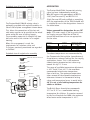
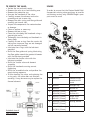
• Unpack the two tailpieces and confirm • The valve must be installed with isolation valves on both the hot and cold water systems as
as possible to the of
valve;
as to allow thereducing
valve to be commissioned
theclose
installation
a sopressure
valve. and tested they are complete with union nuts and correctly.
Correct location of the mixing valve is
compression nuts and olives.
• The valve is supplied with integral strainers on the hot and cold water supplies therefore inline strainers should
not be required.
important
to ensure
that it is accessible for
• The valve is fitted withand
integralservicing.
“listed” non-return valve cartridges which command the water
commissioning
• Locate the sealing gaskets, insert them into supply, therefore the thermostatic valve is protected against cross-flow due to unbalanced
line pressures as required by the Water Supply (Water Fittings) Regulations 1999.
the union nuts against the faces of the
• The valve body is tailpieces and screw the union nuts onto the clearly marked with valve until a tight seal has been made.
Procedure
Assembly
‘C’ for
Cold and a blue indicator and ‘H’ • Remove the compression nuts and olives for Hot and a red from the tailpieces. Locate the inlet filter
indicator.
screens and insert them into the bore of the The valve must be correctly connected to the respective supplies
• The use of sealing compounds must be avoided since they may intrude into
the water supply and impair the valve performance.
• The valve must be so installed that it is readily accessible for commissioning and
maintenance when being installed in accordance with TMV2.
tailpieces up to the shoulder.
• Assemble the valve to the pipework and ensure the hot and cold water pipes have full penetration into the tailpiece.
• Tighten the compression nuts ensuring that the end of the pipe remains in contact with
the filter element.