1
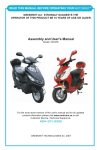
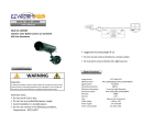
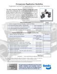
D igital Wireless System
2.4GHz
User Guide
Thank you for purchasing our visual security system. It can help the users to Improve the
working efficiency and provide the security of the mechanical person. We strictly follow the
ISO/TS16949 quality Management systems, product design with the industrial-grade
materials, advanced testing equipment to provide the reliability and stability.
Products meet Chinese MA, European and American FCC, CE, E-MARK, Japan and other
international standards.
Before you request for repair
Features
★Patant on the monitor design, monitor housing is made by ABS which has ability
of high temperature resistant.
Phenomena below are not necessary mean failure with Display.
Please check off per following methods before you request for repair.
★7" High Resolution Color TFT- LCD. LED backlight;
★Auto or manual switch the different channel;
Phenomana
Possible Causes
★8V-32V DC power input, suitable for all kinds of vehicles;
★Monitor circuit has protector for battery reverse(+/-);
★LED backlight display with constant voltage constant current circuit protection design.
(Solve LED work temperature reaches the limit of its current damage and prolong
No Picture
Improper connection with Automobile adapter.
Use of unauthorized power supply. Power Switch is on OFF
position.
service life);
★Monitor OSD menu can set each camera image in 4 mode NOR/MIR/UP/DOWN;
Dark Picture
★Reverse reference line make the safe operation on reversing;
★Two Digital Wireless signal transmit. Support sub-screen and two screens;
★High shock resistant rating: 8G;
No color
Please check contrast and brightness.
Check if color is adjusted, or check if the color
system(PAL/NTSC) is right.
★Car digital wireless camera waterproof: IP69K.
★Camera design to prevent the camera oxidation and atomization.
Notice:
★Before using our products, please read this manual first.
★DC8~32V input, the power cable(red and black) connect with the car battery (power and ground)
★Please make sure all the cables are connected tightly, or else the system will not work well.
★The monitor is not waterproof, please don not place the monitor outdoor.
★Do not open the housing of the camera, otherwise the waterproof device and chipset
inside it will be damaged.
★While driving, please do not watch DVD, etc.
★Please do not use caustic chemicals to wipe the camera and monitor.
Warning
The system maintenance must be maintained by professionals, please do not open and
improve the system!
The system only for the safe operation of machine and equipment, not responsible for
accidents!
This manual is for reference only. if unknown, or any changes, we will give no notice.
The final interpretation right belongs to the manufacturer.
1
Ver:1403A01
110
System
Monitor
I. 7" Monitor Appearance and accessories
I.Digital wireless system connection diagram
antenna
Power Input
Power Input
①Power
Power(Red)
Ground(Black)
CA M1
DC Input: 8-32V
Power(Red)
Ground(Black)
CA M2
DC Input: 11-32V
Power(Red)
Ground(Black)
DC Input: 11-32V
Color TFT-LCD Screen
②Left(Vol-)
Sun Visor
③Right(Vol+)
④Menu/Esc
⑤Down(CH switch)
Bracket Screw
⑥Up(CH switch)
⑦OK
① ②
③ ④
⑤ ⑥
⑦
M
Bracket
Indicator: RED/power on; OFF/Stand by
GREEN FLASH/Pairing
II. 7" Rear view mirror monitor Appearance and accessories
Glass
Color TFT-LCD Screen Indicator
Button
M
Power
Brand Name
Menu/Esc
OK
Fixed Bracked
Right
Left
CH Switch
Speaker(no audio)
Fleet &
Heavy truck
Fork Lift
Construction
machinery
vehicles
Trailer & RV
9
Tail Cable Hole
School Bus
AG Equipment
2
Movable Bracket
Monitor
Camera
III. 9" Monitor Appearance and accessories
I. Digital Wireless camera appearance and dimension(Unit: mm)
●View Angle: 120°
●Power Supply: DC11-32V
●DF-8275(1/4"COLOR CMOS 420TVL)
●Waterproof: IP69K
Color TFT-LCD Screen
①Power
Sun Visor
B
70.5mm
②Left(Vol-)
106.7mm
③Right(Vol+)
75.0mm
Bracket Screw
④Menu/Esc
⑤Down(CH switch)
Digital Wireless Camera
36mm
91.6mm
⑥Up(CH switch)
⑦OK
Bracket
C
II. Digital wireless camera technical Parameters
① ② ③ ④ ⑤ ⑥ ⑦
Indicator: RED/power on; OFF/Stand by
CAMERA
GREEN FLASH/Pairing
COLOR CMOS CAMERA
1/4"COLOR CMOS
Image Pick-up Device
IV. Digital wireless Monitor technical parameters
Display Device
Size
Interface
Resolution
Active Area (mm)
View Angle (LR/UD)
Contrast Ratio
Luminance (nits)
Response Time (ms)
Picture Elements
Color TFT-LCD
Color TFT-LCD
7" Digital Screen
9" Digital Screen
Digital TTL
Digital TTL
800×(RGB)×480
153.60(W)×86.64(H)
L/R: 70/70 U/D: 50/70
0 Lux At Night ( IR LED ON)
Lens furnished
Board lens 2.5mm
Power Supply
DC11~32V
198.0(W)X111.7(H)
500:1
400
300
25
25
DC 12+87V/400ms
Operating Temperature
-20℃ ~+60℃
-20℃~+60℃
Storage Temperature
-30℃~+80℃
-30℃~+80℃
Application Power
Supply
DC8V~32V ( 5W Max)
DC8V~32V ( 5W Max)
Transmit Distance
(No block)
100m
100m
3
Minimum illumination
S/N Ratio
DC 12+ 87V/400ms
Down Load
420TVL
800×(RGB)×480
500:1
NTCS:640(H)×480(V)
Horizontal Resolution
Gain Control
L/R: 70/70 U/D: 50/70
PAL:640(H)×480(V)
Automatic
More than 48db
White Balance
Automatic
Electronic Shutter Control
Automatic
Transmit Power
10 dbm
Operating Temperature
-20°C~+60°C
Storage Temperature
-30°C~+80°C
8
Monitor
Monitor
XI: Monitor Menu Operation:
PAIR
PICTURE
V. 7" Monitor Sun Visor Install/Remove
Nor/Mir
Electronic Lable
Program edition No.
1)Pair: Establish the connection between the monitor and camera, make the system
work in order.
Chose PAIR and press OK to enter the pair. the monitor display: P lease supply
current camera power supply, In pairs please...30. Pairing time is 30s, press
the pair key on the camera within 30s till the monitor show the camera image.
2) Picture setting:
a. Brightness:0-5(Press left/right to adjust);
b. Contrast:0-5(Press left/right to adjust);
c. Color:0-5(Press left/right to adjust).
3) Electronic Label setting: Turn on/off the electronic label on CAM1.
Cam2 no electronic label.
4 ) Mirror/Normal image setting: 4 modes as blow
CAM1
CAM1
CAM1
CAM1
VI. Monitor Bracket Screw Mount
Normal
Mirror
N-UD
M- UD
5) Program edition No.
Note:
1.Turn on the monitor, it will under the auto search mode,
press or
to enter the normal mode, or the keys can not
work.
2.Under the AUTO mode, if only CAM1 or CAM2 working, the monitor will
switch to the working CH automatically, if the CAM1 and CAM2 work together,
the monitor will show the CAM1 image.
7
4
Monitor
Monitor
VII. 7" Monitor mount Dimension(Unit: mm)
IX. 9" Monitor mount dimension(Unit: mm)
255.6
82
149
218
81
B
179
C
50
207
50
244.6
VIII. 7" Rear view mirror monitor mount dimension(Unit: mm)
X. Accessory(Optional)
256.2
42.0
104.5
5
67
U Bracket
Power Cable
80
6
Antenna