1
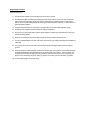
Programming Procedure.
Command sequence:1)
Give the module a RESET command F(25) A(15) to ensure it is inactive.
2)
Now load up the patch memories by first writing the pointer to zero with F(17) A(1), then write consecutive
data to each location specifying 0/1 for each patch. The pointer auto-increments; bit W1 corresponds to
patch 1 and so on to W5; writing CAMAC '0' means ignore this patch pattern (address), '1' means store the
data if this pattern appears.
3)
4)
Write the comparator reference value with F(17) A(0) to select the number of bits required to trigger.
Enable each of the patches (to allow its flag to be set) with F(26) A(0-4).
5)
At this point, any input pulses will be captured if they satisfy the majority logic comparator and match a preloaded 'interesting' pattern.
6)
However, the module will not produce LAM or respond correctly to readout commands until......
7)
You issue a Global Enable command: F(26) A(15). This clears any pre-existing patch flags and enables the
LAM output.
8)
You should now wait for module LAM or use the rear-panel wired-OR trigger signal to start the readout
process.
9)
When this appears, read out the patch words stored with F(2) A(0). The first word you read will be the first to
be captured, identified by which of bits 20-24 are set [bit 20 corresponds to patch 1, bit 24 to patch 5]. The
next patch read out will be the highest 'priority' (numerical - based on patch number) now remaining, and
then the rest in descending sequence. When you get Q='0', that means you have had all the 'good' data.
10) To start capturing again, issue F(26) A(15).