1
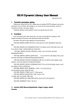
15-2
UG-01085
2014.07.24
MDIO Frame Format (Clause 45)
MDIO Frame Format (Clause 45)
The MDIO core communicates with the external PHY device using frames. A complete frame is 64 bits
long and consists of 32-bit preamble, 14-bit command, 2-bit bus direction change, and 16-bit data. Each
bit is transferred on the rising edge of the management data clock (MDC). The PHY management
interface supports the standard MDIO specification (IEEE802.3 Ethernet Standard Clause 45).
Figure 15-2: MDIO Frame Format (Clause 45)
32 bits
2 bits
2 bits
5 bits
5 bits
2 bits
PRE
ST
OP
PRTAD
DEVAD
TA
00
01
11
Address
Write
Read
Z0
10
16 bits
REGAD/Data
1 bit
Idle
Read
Address/W
rite
Table 15-1: MDIO Frame Field Descriptions—Clause 45
Field
Name
PRE
ST
OP
Description
Preamble. 32 bits of logical 1 sent prior to every transaction.
The start of frame for indirect access cycles is indicated by the <00> pattern. This pattern assures
a transition from the default one and identifies the frame as an indirect access.
The operation code field indicates the following transaction types:
00 indicates that the frame payload contains the address of the register to access.
01 indicates that the frame payload contains data to be written to the register whose address was
provided in the previous address frame.
11 indicates that the frame is a read operation.
The post-read-increment-address operation <10> is not supported in this frame.
PRTAD
DEVAD
TA
The port address (PRTAD) is 5 bits, allowing 32 unique port addresses. Transmission is MSB to
LSB. A station management entity (STA) must have a prior knowledge of the appropriate port
address for each port to which it is attached, whether connected to a single port or to multiple
ports.
The device address (DEVAD) is 5 bits, allowing 32 unique MDIO manageable devices (MMDs) per
port. Transmission is MSB to LSB.
The turnaround time is a 2-bit time spacing between the device address field and the data field of
a management frame to avoid contention during a read transaction.
For a read transaction, both the STA and the MMD remain in a high-impedance state (Z) for the
first bit time of the turnaround. The MMD drives a 0 during the second bit time of the
turnaround of a read or postread-increment-address transaction.
For a write or address transaction, the STA drives a 1 for the first bit time of the turnaround and
a 0 for the second bit time of the turnaround.
Altera Corporation
MDIO Core
Send Feedback