1
TECHNICAL BULLETIN G16/86
MODEL ELECTRONIC RAILWAY GROUP
Modes of Operation
MRCCC has three distinct modes of operation, changed using the Mode Menu:1. Design Mode allows the user to create and modify the track and signalling layout and interlocking
conditions. Full validation is carried out at each step and errors reported to the user. MRCCC always
starts up and closes from design mode (on exit, the mode change will be automatic if required).
You cannot enter Test or Operate Mode if errors exist in the layout data. Use Interlocking Menu – Check
Data if you find the Test and Operate Mode options are disabled on the Mode Menu.
2. Test Mode allows you to simulate the inputs of the layout. You can set Routes and operate the
signalling as you would in operate mode and the interlocking will respond accordingly.
3. Operate Mode allows the user to control the layout. After selecting the Mode, choose the COM Port,
and Link speed for your system and you are in control. It may take a few seconds for the layout states to
update the display.
Design Mode
File Open and Save
At any time in Design Mode, you can choose to save your current layout. Standard Windows File – Save or
File – Save As options are available. To Open a saved file, use File – Open. Files are saved as .MRC files.
File – New creates a new, blank, layout. MRCCC will prompt you on exit or New to save your existing layout
if it has been modified.
RPC Configuration
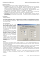
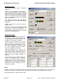
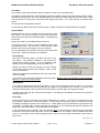
The first data to enter with a new
layout should be the RPC configuration. Use RPC Hardware – Configure
and enter the number of modules of
each type. The software will calculate
the number of bits which are available
to be referenced.
Note, that if you return to this dialog,
the values will be at zero again, and
will require re-entering. You are not
permitted to reduce the number of
modules if you have referenced bits,
which would no longer be available
afterwards.
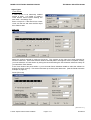
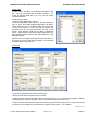
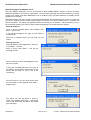
A simple bit Test Utility is provided
using RPC Hardware – Test. This will
only work for up to 32 bytes due to the
addressing limitations of Type 3, 4 and
5 messages.
Editing
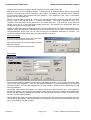
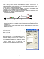
On opening, the ‘selected tile’ will be in the top left corner, or as close to this as possible if objects in an
opened file are positioned there. The ‘selected tile’ is identified as a blue square with a green outline if there
is no object in that position.
With the exception of Routes and RPC configuration, all objects are placed on a unique tile within the 80x64
tile grid. Only one object can be placed in any tile and all objects will be visible in Design Mode.
Pressing F3, or using Modify – Change Data, will bring up the details on an existing object. Pressing Del will
attempt to delete an object. You can not delete an object that has been referenced by another; in all cases,
an error message will detail the reasons.
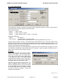
Use the Insert Menu to add objects. The following sections detail each object type and the available
settings. At all stages, the software will provide detailed error messages to explain why you can’t do
something.
G16/86/1/2
Page 2 of 14
© 2005
Stephen Parascandolo & MERG