1
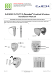
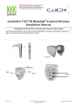
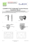
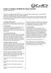
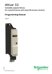
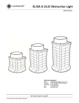
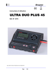
EN
USER
GUIDE
GJD505 & GJD509
GJD505 & GJD509
LASER SCANNERS FOR INDUSTRIAL DOORS
& OTHER SAFETY AND PROTECTION APPLICATIONS
GJD509: max. detection range of 10 m x 10 m
GJD505: max. detection range of 5.0 m x 5.0 m
1
SAFETY
The device contains IR and visible laser diodes.
IR laser: wavelength 905nm; max. output pulse power 75W
(Class 1 according to IEC 60825-1)
Visible laser: wavelength 650nm; max. output CW power 3mW
(Class 3R according to IEC 60825-1)
The visible laser beams are inactive during normal functioning.
The installer can activate the visible lasers if needed.
CAUTION!
Use of controls, adjustments or performance of procedures other than those specified herein
may result in hazardous radiation exposure.
Do not look into the laser
emitter or the visible red
laser beams.
The warranty is void if
unauthorized repairs are
made or attempted by
unauthorized personnel.
Only trained and qualified
personnel may install and
adjust the sensor.
Test the good functioning
of the installation before
leaving the premises.
When used in conjunction with industrial doors the manufacturer of the door system is responsible for carrying out
a risk assessment and installing the sensor and the door system in compliance with the applicable national and
international regulations and standards on door safety and, if applicable, the machinery directive 2006/42/EC. Other
use of the device is outside the permitted purpose and cannot be guaranteed by the manufacturer. The manufacturer
cannot be held responsible for incorrect installations or inappropriate adjustments of the sensor.
INSTALLATION AND MAINTENANCE
Avoid extreme
vibrations.
Do not cover
the front screens.
Avoid exposure to
Avoid direct exposure
sudden and extreme to high pressure
temperature changes. cleaning.
2
Avoid moving objects
and light sources in
the detection field.
Avoid the presence
of smoke and fog in
the detection field.
Avoid condensation.
Do not use aggressive
products to clean
the front screens.
Wipe the front
screens regularly
with a clean and
damp cloth.
Keep the sensor
permanently powered
in environments where
the temperature can
descend below -10°C.
DESCRIPTION
1
2
3
4
5
7
8
6
9
10
1.
2.
3.
4.
5.
laser sweep emission
laser sweep reception
LED-signal (4)
screw for position lock (2)
connector
6.
7.
8.
9.
10.
protection cover
visible laser beam (3)
notch for tilt angle adjustment (2)
adjustable bracket
cable conduit (4)
LED-SIGNAL
1
3
2
4
1.
2.
3.
4.
Detection LED: relay 1 - optional field
Detection LED: relay 2 - safety field
Error LED
Power LED
LED flashes quickly
LED flashes
ERROR LED
POWER LED
detection
error
power
no detection
no error
no power
DETECTION LEDs
TIP!
LED flashes slowly
LED is off
All LEDs can be switched off and on again by remote control:
SYMBOLS
CAT 2
CAT 2
Not
According according
to
to
Caution!
Laser radiation
Remote control
sequence
Possible
remote control
adjustments
Factory
values
EN ISO 13849-1:2008
Pl «d» / CAT2
3
1
MOUNTING
1
Use the adhesive mounting
template to position the sensor
correctly. The grey area indicates
the detection range.
4
Position the bracket and fasten
the 4 screws firmly in order to
avoid vibrations.
7
Position the housing on the
bracket.
4
2
Drill 4 holes as indicated on the
mounting template. Make a hole
for the cable if possible.
5
Open the protection cover, plug
the connector and position the
cable in the slit.
8
Turn the sensor until the two
triangles are face to face.
3
10 cm
Pass the cable +/- 10 cm though
the cable opening. If drilling an
opening is not possible, use the
cable conduits on the back side of
the bracket.
6
Close the protection cover and
fasten it firmly.
2
WIRING
GREEN
POWER SUPPLY +
POWER SUPPLY -
BROWN
WHITE
RELAY 1 - OPTIONAL FIELD
YELLOW
PINK
RELAY 2 - SAFETY FIELD
VIOLET
RED
TEST +
TEST -
BLUE
WHITE/RED
NOT USED
WHITE/BLUE
3
TO
oor
ENABLED
control without test:
connect red and blue wires to power supply (no polarity)
POSITIONING
Unlock the sensor and activate the visible laser
beams.
The visible laser beams indicate approximately
the postion of curtain C1 and limit the angle of
the detection field.
C1
C2
C3
C4
The visible laser beams stay activated for 15
minutes or can be turned off the same way they
were activated.
1
2
Adjust the lateral position of
the detection field.
CAT 2
Adjust the tilt angle of the
detection field with the hex
key.
3
Lock the position of the
mounting bracket to avoid
malfunctioning in case of
extreme vibrations.
CAUTION!
The distance between the inner curtains of the 2 sensors
must be max. 20 cm.
5
4
MOUNTING SIDE
Stay outside of the detection field to avoid disturbances.
Select the corresponding mounting side.
The sensor learns its environment and automatically determines the detection field(s).
Both RED LEDs flash slowly and the 3 visible laser beams automatically light up during 30 seconds.
CAT 2
CAT 2
left
5
right
left
right
centre
WITH BACKGROUND
WITHOUT BACKGROUND
The sensor memorizes the
floor as reference point
and signals a fault when its
orientation is changed.
No reference point, no signal.
SAFETY FIELD DIMENSIONS
LZR® -I110
GJDR® -I100
MAX
MIN
WIDTH
no field
0.5 m
MAX
MIN
9.9 m
no field
0.5 m
5.0 m
5.0 m
HEIGHT
0.5 m
9.9 m
0.5 m
5.0 m
5.0 m
EXAMPLE
for a field width of 6.2 m
IMPORTANT: Test the good functioning of the installation before leaving the premises.
TEACH-IN
Launch a teach-in after changing the sensor position or when new objects are added to or changed in the detection
zone.
The detection field should be free of snow buildups, heavy rain, snowfall, fog or other moving objects.
Wait for the sensor to learn its environment
or lock it by remote control.
3s
max. 30 s
During teach-in, the sensor learns its surroundings and adapts the detection field
shape to these. Objects in the detection field will be cut out.
6
REMOTE CONTROL ADJUSTMENTS (OPTIONAL)
DETECTION CURTAINS
CURTAIN
X
X
X
X
C1
C2
C3
C4
EX:
C1 + C2 active on optional field only
C3 + C4 active on safety field only
deactivate curtain on both fields
C1 active on both fields
C2+C3 active on safety field only
C4 deactivated
activate curtain only on optional field
activate curtain only on safety field
C1
C2
C3
C4
activate curtain on both fields
All curtains active on both fields
The distances between the curtains depend on the mounting height and side. When mounted on the left, the distance between the first
and the last curtain is approximately 10 cm for every meter (mounting height). Example: at 5 m the distance is 50 cm.
UNCOVERED ZONE
5
10
15
CAT 2
25
20
cm
CAT 2
Increase in case of snow, dead leaves, etc.
IMMUNITY FILTER
indoor
outdoor outdoor
indoor outdoor
high
med
low
outdoor outdoor outdoor
high
low
med
CAT 2
CAT 2
CAT 2
Increased immunity to rain, snow, fog...
CAT 2
Increased sensitive (detection of black
objects, ...)
MIN. OBJECT SIZE
(approximate values)
5
off
10
20
15
cm
CAT 2
CAT 2
OUTPUT ACTIVATION DELAY
(approximate values)
off
100
200
300
The outputs are triggered after a constant
detection time of x ms (ex. value 3= 300 ms).
DETECTION FIELD
REDIRECTION
R1
R2
optional
optional
or safety
safety
safety
400
500
600
700
800
900
ms
OUTPUT CONFIGURATION
R1 R2
FACTORY VALUES
R1
A - NO
P - NC
P - NC
A - NO
A = active
P = passive
R2
P - NC
A - NO
P - NC
A - NO
NO = normally open
NC = normally closed
Rx = RELAY OUTPUT
7
OPTIONAL FIELD CONFIGURATIONS
Make sure the white and yellow wires are connected to the corresponding inputs before you choose one of the
following two configurations.
VIRTUAL PUSH BUTTON FOR INDUSTRIAL DOORS
Install 1 or 2 virtual push buttons as activation zone(s) to open the door «manually».
1
Apply the vitual push button sticker(s)
within the opening field.
2
Launch a PB teach-in to configure the detection
zone(s). Launch a new PB teach-in each time the
sensor position is changed or new objects are
added to or changed in the detection zone.
ATTENTION! This PB teach-in is different from the
safety field teach-in.
When the red LED flashes very slowly after 3
seconds, hold your hand in front of the sticker to
learn the detection zone. The green LED flashes 3x
to confirm the selection.
When the red LED flashes again, learn a second
(max. 2) detection zone or wait until the LED
switches to green.
3
3s
3
Change the output redirection if needed.
In order to cancel the virtual push button function, you have to launch a new PB teach-in without any
movement in the detection field. Only then the safety-during-opening can be configured.
OR
SAFETY-DURING-OPENING OF INDUSTRIAL DOORS
Configure a second detection field to secure the door during opening.
1
After setting the mounting side, the safety and the
optional field will have the same dimensions.
2
Adjust the size of the field by remote control.
3
Change the output redirection if needed.
LZR® -I110
LZR® -I100
WIDTH
HEIGHT
same as
safety
field
0.5 m
9.9 m
same as
safety
field
0.5 m
no field
8
0.5 m
5.0 m
9.9 m
no field
0.5 m
5.0 m
HOW TO USE THE REMOTE CONTROL
After unlocking, the red
LED flashes and the sensor
can be adjusted by remote
control.
If the red LED flashes quickly after unlocking, you
need to enter an access code from 1 to 4 digits.
To end an adjustment session,
always lock the sensor.
ADJUSTING ONE OR MORE PARAMETERS
CHECKING A VALUE
x
4
3
1
2
= field width: 4.2 m
= field width is defined by teach-in
RESTORING TO FACTORY VALUES
teach-in
SAVING AN ACCESS CODE
The access code is recommended for sensors installed close to each other.
DELETING AN ACCESS CODE
Enter the existing code
30 minutes after last use, the sensor locks the access to the remote control session.
Cut and restore power supply. The remote control session is accessible again during 30 minutes.
x
X = NUMBER OF FLASHES = VALUE OF THE PARAMETER
9
TROUBLESHOOTING
There is no power.
1 Check cable and connexion.
The polarity of the power
supply is inverted.
1 Check the polarity of the power supply.
All LEDs have been deactivated by remote control.
1 Activate the LEDs by remote control.
Only the blue LED
is on.
The test input is not
connected.
1 Check wiring.
The RED and BLUE cable have to be connected
to the test input or the power supply.
The detection LED
remains green.
The detection field is too
small or deactivated.
1 Check the size of the fields.
2 Launch a teach-in.
The object size is too small.
1 Decrease the min. object size.
Someone or something is
in the detection field.
1 Step out of the field and/or remove the any
object(s) from the field.
The field is touching the
floor, the wall or the door,
which leads to detection.
1 Activate the 3 red beams and check if the
position of the sensor is correct.
If not, adjust the hex screws.
2 Verify the field size.
3 Launch a teach-in.
No background (reference
point) is found.
1 Check the position of the sensor.
2 Check the mounting side setting.
If there is no background, set the mounting side
to value 3 to 5.
3 Launch a new teach-in.
The sensor is masked.
1 Verify and clean the front screens
with a damp cloth.
The power supply voltage
is exceeding the acceptable
limits.
1 Check the power supply voltage.
The sensor exceeds its
temperature limits.
1 Verify the outside temperature where the sensor
is installed. Eventually protect the sensor from
sunlight using a cover.
Internal error
1 Wait a few seconds.
If the LED remains ON, reset the power supply.
If the LED turns on again, replace the sensor.
30 minutes after last use
of the remote control, the
sensor locks the access to
the remote control session.
1 Cut and restore power supply.
The remote control session is accessible again
during 30 minutes.
The batteries in the remote
control are not installed
properly or dead.
1 Verify or replace the batteries.
The remote control is badly
pointed.
1 Point the remote control towards the sensor,
but with a slight angle. The RC should not be
pointed in a right angle in front of the sensor.
A reflective object is in close
proximity to the sensor.
1 Avoid highly reflective material in proximity to
the sensor.
You have to enter an access
code or the wrong code was
entered.
1 Cut and restore power supply.
No code is required to unlock during the first
minute after powering.
No blue LED
The detection LED
remains red.
The orange LED is
flashing and the
detection LEDs are
red.
The orange LED
is on.
The sensor does
not respond to the
remote control.
The sensor does not
unlock.
10
TECHNICAL SPECIFICATIONS
Technology:
Detection mode:
Max. detection range:
Remission factor:
Angular resolution:
Min. detected object size (typ.):
(in proportion to object distance)
Testbody:
Emission characteristics:
IR laser:
Red visible laser:
Supply voltage:
Power consumption:
Peak current at power-on:
Cable length:
Response time:
Output:
Max. switching voltage:
Max. switching current:
Switching time:
Output resistance:
Voltage drop on output:
Leakage current:
Input:
Max. contact voltage:
Voltage threshold:
Response time monitoring input:
LED-signal:
Dimensions:
Material:
Colour:
Mounting angles on bracket:
Rotation angles on bracket:
Tilt angles on bracket:
Protection degree:
Temperature range:
Humidity:
Vibrations:
Pollution on front screens:
Expected lifetime:
Norm conformity:
laser scanner, time-of-flight measurement
motion and presence (EN 12453 Typ. E)
GJD509: 9.9 m x 9.9 m; GJD505: 5.0 m x 5.0 m
>2%
0,3516 °
GJD509: 2,1 cm @ 3 m ; 3,5 cm @ 5 m ; 7 cm @ 10 m
GJD505: 2,1 cm @ 3 m ; 3,5 cm @ 5 m
700 mm x 300 mm x 200 mm (testbody A according to EN 12445)
wavelength 905 nm; max. output pulse power 75 W (CLASS 1)
wavelength 650 nm; max. output CW power 3 mW (CLASS 3R)
10-35 V DC @ sensor side
<5W
1.8 A (max. 80 ms @ 35 V)
10 m
typ. 20 ms; max. 80 ms (+ output activation delay)
2 electronic relays (galvanic isolated - polarity free)
35 V DC / 24 V AC
80 mA (resistive)
tON=5 ms; tOFF=5 ms
typ 30 Ω
< 0.7 V @ 20 mA
< 10 µA
2 optocouplers (galvanic isolated - polarity free)
30 V DC (over-voltage protected)
Log. H: >8 V DC; Log. L: <3 V DC
< 5 ms
1 blue LED: power-on status
1 orange LED: error status
2 bi-coloured LEDs: detection/output status (green: no detection; red: detection)
125 mm (D) x 93 mm (W) x 70 mm (H) (mounting bracket + 14 mm)
PC/ASA
black or white
-45 °, 0 °, 45 °
-5 ° to +5 ° (lockable)
-3 ° to +3 °
IP65
-30 °C to +60 °C if powered; -10 °C to +60 °C unpowered
0-95 % non-condensing
<2G
max. 30 %; homogenous
20 years
2006/95/EC: LVD; 2002/95/EC: RoHS; 2004/108/EC: EMC; 2006/42/EC: MD;
EN 12453:2000 chapter 5.1.1.6, chapter 5.5.1 Safety device E;
EN 12978:2009; EN ISO 13849-1:2008 Pl “d”/ CAT2;
EN 60529:2001; IEC 60825-1:2007; EN 60950-1:2005;
EN 61000-6-2:2005; EN 61000-6-3:2006;
IEC 61496-1:2009; EN 61496-3:2008 ESPE Type 2;
EN 62061:2005 SIL 2; DIN 18650-1:2010 Chapter 5.7.4
Specifications are subject to changes without prior notice.
All values measured in specific conditions.
11
©BEA | Original instructions | 42.7464 / V4 - 11.12
PLEASE KEEP FOR FURTHER USE
DESIGNED FOR COLOUR PRINTING
NOTES:
GJD Manufacturing Limited | Unit 2 | Birch Business Park | Whittle Lane |
Heywood | Lancashire | United Kingdom | OL10 2SX
Tel. +44(0) 1706 363 998 Fax. +44 (0) 1706 363 991 e. [email protected]
12