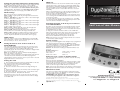
1
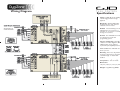
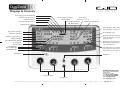
Setting the sensitivity of Detectors ( Pulse Count )
The number of beams ( pulse count ) that need to be triggered before
an alarm output activates can be set at1,2 or 3 can be selected.
Note: when using a DygiZone with GJD detectors where the pulse
count is set on the detector itself, ensure that the detector pulse
count is set to 1.This will apply to D-TECT, OPAL ELITE and OPAL
RFX GJD detectors, but does not apply to the OPAL XL detector.
Mode Settings
One of five modes can be programmed for each Zone.
Mode 1 - 24hr = Lights operate day and night with detection when
auto is selected.
Mode 2 - Link (Zone 1) = Detectors on Zone 1 also activate lights
on Zone 2 when auto is selected.
Mode 2 - Link (Zone 2) = Detectors on Zone 2 also activate lights
on Zone 1 when auto is selected.
Mode 2 - Link (Zone 3) = Detectors on Zone 3 also activate lights
on Zone 4 when auto is selected.
Mode 2 - Link (Zone 4) = Detectors on Zone 4 also activate lights
on Zone 3 when auto is selected.
Mode 3 - 24+L = Outside light will operate day and night with
detection according to the Link settings above.
Mode 4 - STD = Outside lights will only operate at night with
detection. Detectors on that Zone will only operate that zone.
Mode 5 - ALL = All lights on all Zones that have Mode 5 selected
are activated at night with detection from any Zone with Mode 5
selected. Any Zones with ALL selected will be treated as a group.
TSEC output
When this option is selected on the GJD Expansion Unit, the TSEC
output will provide a 12 Volt positive switched signal for the selected
time (in seconds) i.e. off, 1, 5, 10, 20 or 30secs.
Setting the clock to 12 hr or 24 hr mode or to
Clock Off Display
The clock display must be set to 24 hr before the clock time can be
set. Use the red and arrow buttons to advance and to set the clock
mode. If 12 HR mode is selected, AM and PM symbols will
automatically appear. The clock can also be selected to display 24 hour
time or not to display time ( clock off ).
Note: the two timers for each zone will automatically display the
time in the format as selected above.
If the power is turned off and then on without holding down the Zone
1 & 4 buttons, both the illuminated zone LED’s and programme
settings will also remain as they were prior to power down - the clock
display will however be reset to 00:00.
Setting the clock
1) Press and hold down any Zone button until the LCD icon for that
Zone appears and that Zone button is flashing blue.
( the number of zones connected will also be flashing
i.e. the number 1, 2, 3 or 4 )
2) Press the red button six times and the hour digits will begin to
flash.
3) Set the hours by using the up arrow and press the red button again
to set the hour required.
4) The minute digits will now begin to flash - set the minutes in the
same way as the hours. Now press the red button.
Now that the clock is set to the correct time, exit the clock set-up
mode by pressing any of the zone buttons.The time will now display
on the LCD clock.
Pg 5
Walk test
Walk Test Mode has to be selected for each Zone that is being walk
tested. In this mode, as each detector is activated, the audible beep
will sound & the relevant Zone & PIR Number is displayed on the LCD.
The external lights connected to that Zone will turn on for 4
seconds each time a beam is crossed. Each Zone has to be tested
individually.
When in programming mode ( i.e. after pressing and holding one of
the Zone buttons until the LCD display icons show ) use the red
button to scroll to the flashing hand icon.
Select the walk test mode by pressing the up arrow when the hand
icon is showing.The blue LED flashes all the time until the walk test
mode has been exited.
To exit the walk test mode press the red button once - an audible
beep will be heard.The DygiZone will automatically cancel the walk
test mode after five minutes from last trigger.
Switching the lights on & off at pre-set times in
each individual Zone
Each Zone can be programmed to automatically switch the external
lights on & off at pre set times, the on & off times must be on the
same day as each other and must not cross 00:00. Each Zone has two
programmable timers - T1 & T2.
1) Using the red and arrow buttons, advance to the T1 ON time.
When the hour digits begin to flash, enter in the hour at which you
want the lights to turn on, press the red button, repeat for the
minutes and press the red button again to set the time.
Repeat for the T1 OFF Time and repeat for the T2 timer.
Note: if the timers are not required, they should be set to 01:00 for
on and off times (default settings).
The Advanced Multi-function, 4 zone,
security lighting controller &
enunciator
installation Manual
Default settings
When you purchase a DygiZone it has already been pre-programmed
with suggested parameters which are the DEFAULT settings.
To return the DygiZone to its default settings - in the programming
mode, use the red button to scroll to the DEFAULT text icon and
when flashing select press the up arrow key.
Caution: this will return all settings to default and will also reset
the clock.
Default settings are :Zones active = 4
Light on time = 1 minute
Pulse count = 1
T seconds = 5
Clock mode = 24 hr
Mode = 4
Power-up reset - reverts to default settings
This would normally be initiated by a qualified electrician or security
systems installer.
Remove power from the DygiZone.
Press and hold down both the Zone 1 & 4 buttons and then re-apply
the power.The clock will be reset and the programme will revert to
default settings where all the Zones are set to audible and auto
modes i.e. the red and green LED’s will be lit on all Zones.
Note: after a power down & power up, the detectors connected to the
GJD expansion Unit will not activate for the following 2 or 3 minutes.
Maintenance mode
The spanner icon flashes when the keypad is locked and is steady
when the supply voltage to the DygiZone is outside the specification
i.e. below 9 Volts or more than 14 Volts.
IMPORTANT: If the keypad is not locked and the spanner
icon is showing steady, please call a maintenance engineer.
Copyright GJD Manufacturing Ltd. December 2006.
Information correct at time of going to press - errors and omissions accepted.
GJD reserve the right to improve or change specifications without prior notice.
GJD/D/IM/12/06 - 1
Pg 6
GJD Manufacturing Ltd.,
Unit 2, Birch Industrial Estate, Whittle Lane, Heywood OL10 2SX.
Tel: +44 (0) 1706 363998 Fax: +44 (0) 1706 363991
Email: [email protected] Web: www.gjd.co.uk
Master wiring identification
LED lights explained
CABLE FROM EXPANSION UNIT
(SIX-CORE)
Red
+ve 12 Volt
Black
-ve 0 Volt
Blue
Clock "C"
Yellow Data "D"
Green Data "E"
White Remote "R"
Red = Audible Mode - either beep mode or voice message mode
Green = Automatic Mode - works in conjunction with the
photocell in the detector.The external security lights will only be
activated if it is dark and thereby saves energy.
Yellow = Manual Override - the external security light will now
remain on irrespective of detector status - useful for barbeques or
when working outside in the dark for long periods.
Yellow = Lighting Activated - the external security lights have been
activated by a detector and will remain on for the pre set time.
Yellow = Timer Active - the external security lights are on because
the Timer 1 or Timer 2 options are programmed to be active.
SLAVE WIRING FROM MASTER
DYGIZONE (FOUR-CORE)
Red
+ve 12 Volt
Black
-ve 0 Volt
Blue
Clock "C"
White Remote "R"
Power up the DygiZone and you will see -
The DygiZone Control and Monitoring Status
can be set individually for each Zone as follows -
✔ All the LED’s (red, yellow, green and blue buttons) will flash
✔ All LCD icons will light up (there is no audible noise)
The blue LCD backlight does not come on.
✔ The display will automatically clear after 1 minute, or if any button
is pressed.
When the display clears and if nothing is activated ✔ The LCD displays the clock time (automatically defaults to 00:00)
✔ The symbol M appears on the DygiZone which is configured as
the master controller. The letter M does not appear when setting up
a DygiZone as a slave controller.
The three zone LED’s will display whatever zone state has been last
programmed or the default setting. The default setting is audible and
automatic for all active zones.
Zone Indicator Icons explained
Along the bottom of the LCD display up to three sub-zone circular
icons will be displayed above each numbered Zone button. These will
only be displayed when an associated detector connected to A1, A2 or
A3 on the Expansion Unit is activated.
When corresponding detectors connected to A1, A2 or A3 inputs are
activated then✔ The LCD screen will display the zone numbers 1, 2 and 3.
✔ A circle will appear around the zone number if that sub-zone
detector is activated.
The circle flashes on the screen in the same way as the PIR text
whenever a PIR is triggered i.e. the circle flashes for 8 seconds upon activation and then remains
on for pre-programmed time duration ( time on ).
After that time as elapsed, the circle will disappear.
Note: the numbers 1, 2 or 3 always remain steady and never flash.
When the PIRs have not been activated-
✔ The large circular blue Zone buttons (1-4) will not be illuminated.
✔ LCD blue backlight will be switched off.
✔ The clock and M display will remain visible but all other icons on
the LCD are turned off.
✔ The zone status LED’s that are required will be displayed.
Zone Status Icons
(only visible when the zone button is pushed).
At the top and in the middle of the LCD, three zone status icons will
be displayed in various combinations, depending on how the zone has
been set up.
1) A light bulb icon represents external lights are on from a detector
activation, manual override mode or timer operation and mimics the
yellow LED.
2) The musical note icon is shown when the audible mode is selected
and mimics the red LED.
3) If voice message mode has been selected (vs beep) then the
microphone icon will also display on the LCD.
4) The stick man icon represents the automatic mode and mimics the
green LED
All of these are more fully described below Pg 2
1) Pressing a Zone button selects the Zone to be set up.The LED’s
and the LCD display icons will display the current status
e.g. Green LED and stick man means auto mode has been selected.
2) A second press on the same button will now light the red LED
(green LED turns off).The musical note icon will now show on the
LCD plus a microphone symbol if voice message has been selected.
3) Pressing the zone button again will turn off all the LED’s & icons.
4) Press once more and the yellow LED lights and the light bulb icon
displays in the LCD. This now sets the Dygizone to manual mode for
that specific zone and the lights will come on and stay on.
5) One more press and both the green and the red LED’s come on
indicating that audible and automatic mode have been selected.
Locking the key pad
Locking the key pad prevents accidental programme or setting changes.
To lock - press and hold down Zone buttons 1 and 4 at the same
time - a single beep will be heard and the spanner symbol on the
keypad will flash to confirm that the key pad is locked.
To unlock - repeat the action and two beeps will be heard, and the
spanner symbol will disappear.
When a PIR detector in a zone is triggered, the
following zone information is displayed LCD Information and Text
✔ PIR text will flash for approximately 8 seconds for that zone.
✔ The blue LCD backlight will come on for about 6 seconds during
the trigger state and will remain on after the trigger has occurred.
✔ The text remains on for a time duration ( time on ) equal to the
time that has been pre-set in the Mins Setting .
If the DygiZone is triggered during the hours of darkness ✔ The external security light will also be activated for the pre-set time.
Note: if another PIR activation occurs on any other zone then the
text will be displayed for that new zone for the same pre-programmed
time on duration.
Recording a voice message to audibly indicate
which zone has been activated
1) Press and hold the red button until the microphone symbol
appears on the LCD.
2) Press the required Zone button once and then release. As you
release the zone button a horizontal bar with ten segments will appear
below the microphone symbol on the LCD. This indicates the amount
of recording time available where each segment is equivalent to one
second therefore a ten second message can be recorded.
3) Speak into the microphone on the front cover of the DygiZone to
indicate location ( e.g. patio area, front door, side garden etc )
4) When you have finished speaking into the microphone quickly press
the zone button again ( there will be no audio beep ).
5) The recorded message will now automatically play back. If you are
Pg 3
satisfied with the message do nothing but if you wish to re-record the
message repeat steps 1 to 5.
You now need to set-up each recorded message for the
appropropriate zone 6) Press and hold down the red button until the microphone symbol
appears in the LCD and then release.
7) Now press and continue to hold down the zone button for which
the voice message is to apply, until an audible beep is heard - release
the zone button and the programming has been completed.
The voice message mode can be confirmed by pressing the zone
button once and a microphone symbol will appear on the LCD if
audible mode has been pre-selected.
Note 1: the normal default status for sensor activation is an audible
beep i.e. one beep for Zone 1, two beeps for Zone 2 and so on.
Note 2: it is possible to mix both audible beeps and recorded
messages e.g. Zone 1 could be in beep and Zone 2 could be in
recorded voice playback.
To change from a voice message to a beep, repeat Steps 6 & 7.
Engineer programming
Whichever Zone requires adjustment, press and hold down that Zone
button until the programming options show on the LCD display.
The ZONES number will be flashing on the LCD display, to change this
option press the UP button until the required number is showing then
press the RED button. If no adjustment is required press the RED
button.This will store the change and move on to adjust the TIME
MINS. Repeat the above process until all changes have been completed
then press any Zone button to exit programming.
If no buttons are pressed for 30 seconds the DygiZone will
automatically exit the programming mode.
Selecting the number of active Zones
1) Press and hold down the Zone 1 button, this will enter
programming mode.
2) The Zone number will flash and can be changed using the up arrow
button.
3) Press the red button to confirm the number of Zones.
Unused zones will be cleared i.e. no LCD information will display and
no LED’s will work for that Zone. An audible beep will be heard if any
of the unused Zone buttons are pressed, but no action will be taken.
4) Press Zone 1 button to exit the programming mode.
Setting the time that the lights stay on
When a detector is triggered and if that Zone has been set to the
automatic mode (green LED), the lights will turn on and stay on for
the time programmed using the TIME setting in the programme
software.This can be selected to be 1,2,3,4,5,8,12,16 or 24 minutes
using the red and arrow buttons.When set simply press any of the
ZONE buttons to exit the programming mode.
Optional DygiZone slave controllers
Up to two additional DygiZone controllers can be connected to the
system, additional Expansion Units or power supply will be required to
provide the 12 Volt supply. Only the Master controller can be used to
set the programme options but different voice messages can be
recorded on the remotely located Slave controllers.The keypad can
also be locked on the Slave controllers otherwise the slaves will mimic
the Master.
Changing a button selection on the Master DygiZone will instantly
change the settings on the Slave controllers.
Changing a button selection on either of the Slave controllers will
instantly change the setting on that Slave and the Master, the setting on
the other Slave will change within one minute.
It is recommended that the DygiZone which will be used the most
should be configured as the Master.
Pg 4
Wiring Diagram
Specifications
Supply 12 VDC @ 20 mA standby.
100 mA triggered with message
playback.
Display Blue back-lit LCD display
showing real time clock, detector
activation and zone status.
MAINS SUPPLY VIA
SUITABLE RCD/MCB
Audible Internal warning tone with
individual tones for each zone or
selectable 10 second voice recordable
message for each zone.
Control Four individual zone buttons
for selecting zone status and
programming options.
System configuration Normally
1 Master and 1 Slave DygiZone. One
additional Slave can be added if
required. Requires GJD Expansion Units.
Time control Two individual on/off
timers per zone.
Mounting Indoor use only. Mount in a
clean dry location. Can be mounted on
a standard single or double flush
backbox.
Temperature -100C to +550C.
Dimensions
134 ( W ) x 87 ( H ) x 30 ( D ) mm
Weight 190g NET, 260g GROSS
Displays & Controls
Voice Message Selected Indicator
Walk Test Mode Indicator
Light On Indicator
Recorded Voice Message
- Horizontal Bar
Pulse Count
Indicator (1,2 or 3)
Programmable Timers
On, Off Indicator
Automatic Mode Indicator
Audible Mode Indicator
Default Setting Indicator
Clock Display - AM or PM appears
automatically in 12 hour mode
Zone Active Indicator
Mode Display (1-5)
PIR Active Indicator
Master Controller Indicator - no
symbol indicates if controller is
acting as a slave
Number of Active Zones
T Output (SECS)
Time On Indicator (MINS)
12 or 24 hour
Clock Setting
Red LED Light
Green LED Light
Yellow LED Light
Keyboard Locked Indicator also indicates when voltage is
out of specification
Sub Zone Detector Indicators
(circle appears only when a
detector has been triggered)
Microphone
Up Button
1 - 4 Zone Buttons
Red Button
Copyright GJD Manufacturing Ltd. December 2006. Information correct at time of going to press - errors and omissions accepted. GJD reserve the right to improve or change specifications without prior notice.
GJD Manufacturing Ltd.,
Unit 2, Birch Industrial Estate,
Whittle Lane,
Heywood OL10 2SX.
Tel: +44 (0) 1706 363998
Fax: +44 (0) 1706 363991
Email: [email protected]
Web: www.gjd.co.uk
GJD/D/IM/12/06 - 2