1
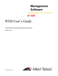
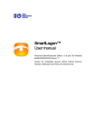
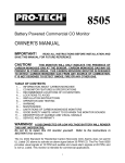
IEEE 802.11g Access Point
User’s Guide
Version 1.0, May 2003
1
Copyright Statement
No part of this publication may be reproduced, stored in a retrieval system, or transmitted in
any form or by any means, whether electronic, mechanical, photocopying, recording or
otherwise without the prior writing of the publisher.
Windows™ 95/98 and Windows™ 2000 are trademarks of Microsoft® Corp.
Pentium is trademark of Intel.
All copyright reserved.
2
Table of Contents
Regulatory Information.......................................4
How to View the device Status .......... 32
Introducing the 802.11G ACCESS POINT .......5
How to View the System Log.............. 33
Overview of the Device .........................5
DHCP Client Table............................... 33
802.11G ACCESS POINT Features ........6
Wireless Client Table .......................... 33
Network Configuration Examples .........7
Bridge Table........................................ 34
As An Access Point..........................7
Upgrading Firmware ........................... 34
As A stand-alone repeater ...............8
How to Save or Restore Configuration Changes
As A point to multi-points Bridge ....8
............................................................. 35
Setting Up the device............................9
How to Reboot your 802.11G ACCESS POINT
Static IP ...........................................9
............................................................. 35
Automatic IP ....................................9
What if you Forgot the Password?...... 36
Installing the 802.11G ACCESS POINT .....10
Command Line Interface .......................... 37
What’s in the Box?...............................10
General guidelines .............................. 37
Connecting the Cables ........................11
Express Mode vs. Advanced Mode of operation
High Level Configuration Steps Required for the
............................................................. 38
802.11G ACCESS POINT......................11
Conventions ........................................ 38
Setting up a Windows PC or wireless client as
Command List ..................................... 39
DHCP clients........................................12
System Commands ............................. 39
A Look at the Front Panel....................14
Port...................................................... 46
Connecting More Devices Through A Hub To The
Filtering ............................................... 48
802.11G ACCESS POINT......................15
DHCP Server........................................ 49
Basic Configuration of the 802.11G ACCESS POINT
SNMP ................................................... 51
...................................................................16
Diagnostics ......................................... 53
Logging On...........................................17
Security ............................................... 56
Setup Wizard........................................17
Wireless............................................... 58
Time settings .................................17
Product Specification ............................... 61
Device IP Settings .........................18
Wireless Settings ...........................20
Advanced Settings ....................................22
Password Settings...............................22
System Management ...........................22
SNMP Settings .....................................24
DHCP Server Settings..........................25
MAC Filtering Settings.........................26
Wireless Settings.................................27
Operational Mode ................................28
Radius Settings ...................................29
Managing the 802.11G ACCESS POINT.....32
Regulatory Information
Federal Communication Commission Interference Statement
This equipment has been tested and found to comply with the limits for a Class B digital device,
pursuant to Part 15 of the FCC Rules. These limits are designed to provide reasonable protection
against harmful interference in a residential installation. This equipment generates, uses and can radiate
radio frequency energy and, if not installed and used in accordance with the instructions, may cause
harmful interference to radio communications. However, there is no guarantee that interference will
not occur in a particular installation. If this equipment does cause harmful interference to radio or
television reception, which can be determined by turning the equipment off and on, the user is
encouraged to try to correct the interference by one of the following measures:
- Reorient or relocate the receiving antenna.
- Increase the separation between the equipment and receiver.
- Connect the equipment into an outlet on a circuit different from that to which
the receiver is connected.
- Consult the dealer or an experienced radio/TV technician for help.
FCC Caution: To assure continued compliance, (example - use only shielded interface
cables when connecting to computer or peripheral devices) any changes or modifications
not expressly approved by the party responsible for compliance could void the user’s
authority to operate this equipment.
This device complies with Part 15 of the FCC Rules. Operation is subject to the following
two conditions: (1) This device may not cause harmful interference, and (2) this device
must accept any interference received, including interference that may cause undesired
operation.
IMPORTANT NOTE:
FCC Radiation Exposure Statement:
This equipment complies with FCC radiation exposure limits set forth for an uncontrolled
environment. This equipment should be installed and operated with minimum distance
20cm between the radiator & your body.
This transmitter must not be co-located or operating in conjunction with any other antenna or
transmitter.
4
1
Chapter
Introducing the 802.11G ACCESS POINT
Overview of the Device
The 802.11G ACCESS POINT is an access-point based on IEEE 802.11g based 2.4-GHz
radio technology. It contains an 802.11g and a full-duplex 10/100 LAN interfaces. The
802.11G ACCESS POINT can function as a simple Access Point (AP), and act as the center
point of a wireless network supporting a data rate of up to 54 Mbps. It can also connect these
wireless devices to wired network through the LAN interface.
The 802.11G ACCESS POINT can also function in a repeater mode, which is used to extend
the physical coverage of the wireless network. Finally, the 802.11G ACCESS POINT can also
function in a Wireless Distribution System (WDS) mode. Multiple 802.11G ACCESS
POINT’s can be configured to operate in the WDS mode to inter-connect wired LAN
segments that are attached to these 802.11G ACCESS POINT’s.
Since the 802.11g share the same 2.4GHz radio band as the 802.11b technology, it can interoperate with existing 11Mbps 802.11b devices. Therefore you can protect your existing
investment in 802.11b client cards, and migrate to the high-speed 802.11g standard as your
needs grow.
To address growing security concerns in a wireless LAN environment, different levels of
security can be enabled in the 802.11G ACCESS POINT, including:
• To disable SSID broadcast to restrict association to only those client stations that are already
pre-configured with the correct SSID
• To enable WEP (Wireless Encryption Protocol) encryption to protect the privacy of your
data.
• Support of Access List Control to allow you to grant/deny access to/from specified
wireless stations
• Provisioning of centralized authentication through Radius Server(s).
5
IEEE 802.11g Access Point User’s Guide
802.11G ACCESS POINT Features
Compliant with 802.11g and 802.11b standards with roaming capability
Support of the standard access point mode for connection to wireless clients
Support of the Repeater Mode to extend infrastructure coverage
Support of the WDS mode for interconnecting LAN segments
Built-in DHCP Server to Assign IP Addresses to wireless clients automatically
Multiple security measures: to disable SSID broadcast, to define Access Control List,
to enable WEP based encryption (up to 128 bits), and enhanced Security with
802.1x using a primary and a backup Radius Server
Extensive monitoring capability such as event logging, traffic/error statistics
monitoring
Easy configuration and monitoring through the use of a Web-browser based GUI,
a Command Line Interface (CLI) through a remote telnet session, or SNMP
commands from a remote SNMP management station
Setup Wizard for easy configuration/installation
6
Network Configuration Examples
A group of wireless stations communicating with each other is called a Basic Service Set (BSS)
and is identified by a unique SSID.
When a 802.11G ACCESS POINT is used, it can be configured to operate in the following
three network configurations
AS AN ACCESS POINT
When configured in the Access Point mode, the 802.11G ACCESS POINT allows a group of
wireless stations to communicate with each other through it. Such a network is called an
Infrastructure BSS.
The 802.11G ACCESS POINT further provides bridging functions between the wireless
network and the wired LAN network.
When multiple access points are connected to the same LAN segment, stations can roam
from one 802.11G ACCESS POINT to another without losing their connections, as long as
they are using the same SSID. This is shown in the diagram below.
7
IEEE 802.11g Access Point User’s Guide
AS A STAND-ALONE REPEATER
The purpose of a repeater is to expand an existing infrastructure BSS. When configured to
operate in the Repeater Mode, the 802.11G ACCESS POINTs sit between wireless stations
and a “root” AP whose BSS is being expanded, as shown below:
AS A POINT TO MULTI-POINTS BRIDGE
When configured to operate in the Wireless Distribution System (WDS) Mode, the 802.11G
ACCESS POINT provides bridging functions between the LAN behind it and separate LANs
behind other AP’s operating in the WDS mode. The system will support up to eight such AP’s
in a WDS configuration.
Note that a 802.11G ACCESS POINT running in the WDS mode can also support wireless
stations simultaneously, as shown in the left most AP in the diagram below:
8
Setting Up the device
The 802.11G ACCESS POINT can be managed remotely by a PC through either the wired or
wireless network. To do this, the 802.11G ACCESS POINT must first be assigned an IP
address, which can be done using one of the following two methods.
STATIC IP
The default IP address of the LAN interface of a 802.11G ACCESS POINT is a private IP
address of 192.168.1.1, and a network mask of 255.255.255.0. This means IP addresses of other
devices on the LAN should be in the range of 192.168.1.2 to 192.168.1.254.
This IP address can be modified to either a different address in this same subnet or to an
address in a different subnet, depending on the settings of the DHCP server in the network.
AUTOMATIC IP
The 802.11G ACCESS POINT can also be configured to “obtain” an IP address
automatically from a DHCP server on the network. This address is called “dynamic” because
it is only dynamically assigned to the device, which may change depending on the IP assignment
policy used by the DHCP server in the network. Since the IP address in this case may change
from time to time, this method is not recommended - unless the user uses UPnP or other
management tools that do not depend on a fixed IP address.
9
2
Chapter
Installing the 802.11G ACCESS POINT
This section describes the installation procedure for the 802.11G ACCESS POINT. It starts
with a summary of the content of the package you have purchased, followed by steps of how
to power up and connect the 802.11G ACCESS POINT. Finally, this section explains how to
configure a Windows PC to communicate with the 802.11G ACCESS POINT.
What’s in the Box?
The 802.11G ACCESS POINT package contains the following items:
One 802.11G ACCESS POINT 802.11g Access Point
.
One 5V AC power adapter with a barrel connector
CD of the 802.11G ACCESS POINT User’ Guide
10
Connecting the Cables
The Back Panel of the 802.11G ACCESS POINT appears as follows:
Follow these steps to install your 802.11G ACCESS POINT:
Step 1.
Connect a LAN hub to the LAN port on the 802.11G ACCESS POINT using
the supplied LAN cable.
Step 2.
Connect the power adapter to an electrical outlet and the 802.11G ACCESS
POINT.
High Level Configuration Steps Required for the 802.11G ACCESS POINT
This section describes configuration required for the 802.11G ACCESS POINT before it can
work properly in your network.
First, it is assumed that in your LAN environment, a separate DHCP server will be available
for assigning dynamic (and often private) IP addresses to requesting DHCP clients. This
means that the 802.11G ACCESS POINT normally will not need to enable the DHCP server
function.
Additionally, since you need to perform various configuration changes to the 802.11G
ACCESS POINT, including the SSID, Channel number, the WEP key, …, etc., it is necessary
to associate a fixed IP address with the 802.11G ACCESS POINT, which is why the 802.11G
ACCESS POINT will be shipped with a factory default private IP address of 192.168.1.1 (and
a network mask of 255.255.255.0).
Therefore, during the system installation time, you need to build an isolated environment with
the 802.11G ACCESS POINT and a PC or a wireless client, and then perform the following
steps:
Manually change the IP address of the PC/wireless client to become 192.168.1.2
11
IEEE 802.11g Access Point User’s Guide
Connect the PC/wireless client to the 802.11G ACCESS POINT and change its configuration
to a static IP address reserved by your LAN administrator based on the DHCP server setting.
For example, if the DHCP server assigns IP addresses of range 192.168.23.1-192.168.23.254 to
DHCP client devices, it can reserve 192.168.23.10 for the 802.11G ACCESS POINT. Please
note that at this point the PC/wireless client will lose communication contact with the 802.11G
ACCESS POINT, as they no longer belong to the same IP network address space.
Change the setting of the PC/wireless client back to “obtain IP addresses dynamically”.
From then on, any wireless client configured to “obtain IP addresses dynamically” will work
with the AP, with each other, and with devices on the wired LAN network.
Setting up a Windows PC or wireless client as DHCP clients
The following will give detailed steps of how to configure a PC or a wireless client to “obtain
IP addresses automatically”. For other types of configuration, please refer to the
corresponding user manual.
For the case of using a LAN attached PC, the PC must have an Ethernet interface installed
properly, be connected to the 802.11G ACCESS POINT either directly or through an external
LAN switch, and have TCP/IP installed and configured to obtain an IP address automatically
from a DHCP server in the network.
For the case of using a wireless client, the client must also have an Ethernet interface installed
properly, be physically within the radio range of the 802.11G ACCESS POINT, and have
TCP/IP installed and configured to obtain an IP address automatically from a DHCP server
in the network.
Then perform the following steps for either of the above cases. To configure types of
workstations other than Windows 95/98/NT/2000, please consult the manufacturer’s
documentation.
Step 1.
From the Win95/98/2000 Start Button, select Settings, then
Control Panel. The Win95/98/2000 Control Panel displays.
Step 2.
Double-click on the Network icon.
Step 3.
Check your list of Network Components in the Network
window Configuration tab. If TCP/IP has already been
installed, go to Step 8. Otherwise, select Add to install it now.
Step 4.
In the new Network Component Type window, select
Protocol.
12
In the new Select Network Protocol window, select
Microsoft in the Manufacturers area.
Step 5.
In the Network Protocols area of the same window, select
TCP/IP, then click OK. You may need your Win95/98 CD
to complete the installation. After TCP/IP installation is
complete, go back to the Network window shown in Step 4.
Step 6.
Select TCP/IP in the list of Network Components.
Step 7.
Click Properties, and check the settings in each of the TCP/IP
Properties window:
Bindings Tab: both Client for Microsoft Networks and File
and printer sharing for Microsoft Networks should be
selected.
Gateway Tab: All fields should be blank.
DNS Configuration Tab: Disable DNS should be selected.
IP Address Tab: Obtain IP address automatically should be
selected.
Step 8.
With the 802.11G ACCESS POINT powered on, reboot the
PC/wireless client. After the PC/wireless client is re-booted,
you should be ready to configure the 802.11G ACCESS
POINT. See Chapter 3.
The procedure required to set a static IP address is not too much different from the procedure
required to set to “obtain IP addresses dynamically” - except that at the end of step 7, instead
of selecting “obtain IP addresses dynamically, you should specify the IP address explicitly.
13
IEEE 802.11g Access Point User’s Guide
A Look at the Front Panel
The LEDs on the front of the 802.11G ACCESS POINT reflect the operational status of the
unit. The status of the LAN, the 802.11g, and power can be monitored from this display.
Power
LAN
802.11g
802.11G ACCESS POINT LED Description
Label
802.11g
LAN
POWER
Steady Light
Link is active
Link is active
Power
OFF
No Wireless
connection
No LAN connection
No Power
FLASH
XMT/RCV Data
XMT/RCV Data
N/A
14
Connecting More Devices Through A Hub To The 802.11G ACCESS POINT
The 802.11G ACCESS POINT provides an RJ45 LAN interface which you can use to
connect to a PC or an external hub.
Connect to the
LAN port and set
Uplink button to
“Uplink”
Plug this end into
any port of a
10Base-T repeater
hub
15
3
Chapter
Basic Configuration of the 802.11G ACCESS POINT
This section describes the basic configuration procedure for the 802.11G ACCESS POINT. It
describes how to set up the 802.11G ACCESS POINT for Infrastructure BSS operation, and
the configuration of the local LAN environment.
Although the Command Line Interface (CLI) may also be used to configure the 802.11G
ACCESS POINT, the browser-based configuration mechanism is the tool of choice.
The 802.11G ACCESS POINT is designed so that all basic configuration may be effected
through the a standard Web browser such as Internet Explorer.
From a PC or a Wireless client that has been configured as described in Chapter 2, enter the IP
address of the 802.11G ACCESS POINT as the URL in your browser.
Note: The IP address of your PC must be in the same IP subnet as the 802.11G ACCESS POINT.
16
The Home Page of the 802.11G ACCESS POINT screen will appear, with its main menu
displayed on the upper-side of the screen. The main menu includes the following choices:
Setup Wizard, Device Status, System Tools, Advanced Settings and Help choices, which can
be used to navigate to other menus.
Logging On
If you attempt to access a configuration item from the browser menu, an administrator login
screen will appear, prompting you to enter the password in order to log on.
If you are logging on for the first time, you should use the factory default setting “password”.
The password is always displayed as a string of asterisks (“*”). Clicking the LOG ON button
will begin the configuration session.
Setup Wizard
The Setup Wizard will guide you through a series of configuration screens to set up the basic
functionality of the device. After you finish configuring these screens and press the “finish”
button on the last screen, all your configuration modifications will take effect.
TIME SETTINGS
After logging in, the time settings page appears. The AP time is automatically set to the local
time of the management PC the first time a connection is made. To modify the AP’s clock,
modify the appropriate fields, and click “NEXT”.
17
IEEE 802.11g Access Point User’s Guide
DEVICE IP SETTINGS
The Device IP setting screen allows you to configure the IP address and subnet of the AP
on the LAN. Although you can rely on a DHCP server to assign an IP address to the 802.11G
ACCESS POINT automatically, it is recommended that you configure a static IP address
manually in most applications.
If you choose to assign the IP address manually, check the button that says “Assign static IP
to this device” and then fill in the following fields
IP Address and IP Subnet Mask: These values default to 192.168.1.1 and 255.255.255.0,
respectively. It is important to note that similar addresses fall within the standard private IP
address range and it is an essential security feature of the device. Because of this private IP
address, this device can no longer be accessed (seen) from the Internet.
Gateway IP Address: Enter the IP address of your default gateway
18
DNS Server: The Domain Name System (DNS) is a server on the Internet that translates
logical names such as “www.ebay.com” to IP addresses like 209.103.14.2. In order to do this, a
query is made by the requesting device to special DNS servers to provide the necessary
information. If your system administrator requires you to manually enter DNS Server
addresses, you should enter them on this page.
Then you should press Next to get to the next screen.
If you choose to use a DHCP Server to assign IP address automatically, check the button that
says, “Use the DHCP protocol to automatically get the IP address for this device”, and
then press Next to the next screen. Again, as a reminder, it is recommended that your
802.11G ACCESS POINT should be assigned a static IP address in order for you to be able
to manage it later on.
19
IEEE 802.11g Access Point User’s Guide
WIRELESS SETTINGS
Network Name (SSID): The SSID is the network name used to identify a wireless network.
The SSID must be the same for all devices in the wireless network. Several access points on a
network can have the same SSID. The SSID can be up to 32 characters long.
Disable SSID Broadcasting: An access point periodically broadcasts its SSID, along with
other information, which allows client stations to learn its existence while searching for access
points in the wireless network. Select Disable if you do not want the device to broadcast the
SSID.
WLAN Operation mode: Although the wireless module is IEEE 802.11g and 802.11b
complient, choosing 802.11G only may increase your wireless performance.
20
Regulatory Domain: Please make sure that your regulatory domain match your region. The
default value are ETSI. For most region, ETSI may be the better choice.
Channel: Select the channel from the available list to match your network settings. All devices
in the wireless network must use the same channel.
Note: The available channel numbers are different from country to country.
USA and Canada: CH01~11, Europe: CH01~CH13, Japan: CH01~CH14, France:
CH10~CH13, Spain: CH01~CH13
You can use encryption to protect your data when you are transmitting data across wireless
channels.
WEP Selection: The 802.11G ACCESS POINT allows you to use data encryption to secure
your data from being eavesdropped by unauthorized wireless users. We allow up to four 40-bit
encryption keys (WEP40) and four 128-bit encryption keys (WEP128) to be configured
(using either the ASCII or Hexadecimal format) and selected.
WEP Key Setting: The length of a WEP40 key must be equal to 5 and WEP128 key equal to
13. Once you enable the WEP function, please make sure that the same WEP key is used by
both the 802.11G ACCESS POINT as well as the wireless client stations.
Note: Some wireless client cards are used for Hexadecimal digits only. Please note that when
configuring WEP keys, a WEP128 ASCII key looks like “An ASCII key!”(13 characters), while
a WEP40 Hex key looks like “44-12-24-A8-B2”(5 characters).
Finish Setup Wizard and Save Your Settings
After stepping through the Wizard’s pages, you can press the FINISH button for your
modification to take effect. This will also cause your new settings to be saved into the
permanent memory in your system.
Congratulations! You are now ready to use the 802.11G ACCESS POINT.
21
IEEE 802.11g Access Point User’s Guide
Note: If you change the AP’s IP address, as soon as you click on FINISH you will no longer be able to
communicate with your 802.11G ACCESS POINT. You need to change your IP address and then re-boot
your computer in order to resume the communication.
Advanced Settings
The advanced settings tab on the top row of buttons will allow you to perform modifications
that normally you may not need to do for basic operations. The exception to this is changing
your password from the default factory setting. This is highly recommended for security
purposes.
Password Settings
The default factory password is “password”. To change the password , press the Password
Settings button to enter the Password Settings screen, enter the current password followed by the
new password twice. The entered characters will appear as asterisks.
System Management
Clicking the System Management button allows system related parameters to be configured
for the 802.11G ACCESS POINT.
22
Management Utility Port Definition: The standard port settings for the HTTP Web server
and the Telnet utility may be replaced by entering new port numbers in these fields.
Management Session Time-out: This setting specifies the duration of idle time (inactivity)
before a web browser or telnet management session times out. The default time-out value is
10 minutes.
UPnP: The AP’s Universal Plug and Play (UPnP) feature allows a Windows XP/ME PC to
discover this AP and automatically show an icon on the screen. Subsequently a user can
double-click the icon to access this AP directly (without having to specify its IP address).
Syslog: Syslog is an IETF (Internet Engineering Task Force - the Internet standards body)conformant standard for logging system events (RFC-3164). When the 802.11G ACCESS
POINT encounters an error or warning condition (e.g., a log-in attempt with an invalid
password), it will create a log in the system log table. To be able to remotely view such system
log events, you need to check the Enable Syslog box, configure the IP address of a PC where
a Syslog daemon is always running in the background. When doing so, the 802.11G ACCESS
POINT will send logged events over the network to the PC for future viewing.
Syslog server IP address: The IP address of the PC where the Syslog daemon is running.
23
IEEE 802.11g Access Point User’s Guide
SNMP Settings
This screen allows you to configure general system parameters including the system name, the
location and contact information. Additionally, you can configure the 802.11G ACCESS
POINT to send SNMP Traps to remote SNMP management stations. Traps are unsolicited
alert messages that 802.11G ACCESS POINT sends to remote management stations.
System Name: A name that you assign to your 802.11G ACCESS POINT.
System Location: Description of where your 802.11G ACCESS POINT is physically located
System Contact: Contact information for the system administrator responsible for managing
your 802.11G ACCESS POINT
24
Community String For Read: A password used by a remote SNMP management station to
issue SNMP Read requests
Community String For Write: A password used by a remote SNMP management station to
issue SNMP Read/Write requests
Name: The name of the remote SNMP manager
IP Address: The IP address of the SNMP trap manager
SNMP Trap Manager List: The list of SNMP trap managers configured; entries may be
deleted by selecting the entry and then pressing the DELETE SELETED button
DHCP Server Settings
The DHCP server option allows the 802.11G ACCESS POINT to assign IP addresses to DHCP
client devices on your wired or wireless LAN to obtain IP addresses automatically.
25
IEEE 802.11g Access Point User’s Guide
Enable DHCP server: To enable the DHCP server option of the 802.11G ACCESS POINT
Dynamic IP Address Assignment
When the DHCP server option is enabled, the 802.11G ACCESS POINT will assign IP
addresses from an available IP address pool (e.g., 192.168.1.1 – 192.168.1.254). If you wish to
avoid using certain addresses (so as to assign them to other special devices), you can specify
the available IP address pool in the From/To boxes and the press SUBMIT.
From: The beginning IP address of a range
To: The ending IP address of a range
Static IP Address Assignment
If you require certain PCs to always obtain the same IP addresses, enter each PC’s MAC
address and the corresponding IP address desired and press ADD
MAC address: The MAC address of the PC
IP address: The IP address to assign to the PC with the above MAC address
DHCP Client List: The list of all static MAC-address/IP-Address pairs configured. Entries
may be deleted by checking the Select box followed by pressing DELETE SELECTED.
MAC Filtering Settings
The 802.11G ACCESS POINT allows you to define a list of MAC addresses that are allowed
or denied to access the wireless network
Disable MAC address control list: When selected, no MAC address filtering will be
performed.
Enable GRANT address control list: When selected, data traffic from devices listed will be
allowed in the network.
Enable DENY address control list: When selected, data traffic from devices listed in the
table will be denied/discarded by the network.
26
The table lists all configured MAC Filter entries. To delete entries, check the corresponding
select boxes and then press DELETE SELECTED
Wireless Settings
Beacon Interval: The 802.11G ACCESS POINT broadcasts beacon frames regularly to
announce its existence. The beacon Interval specifies how often beacon frames are transmitted
- in time unit of miniseconds. Its default value is 100; a valid value should be between 1 and
65,535.
27
IEEE 802.11g Access Point User’s Guide
RTS Threshold: RTS/CTS frames are used to gain control of the medium for transmission.
Any unicast (data or control) frames larger than specified RTS threshold must be transmitted
following the RTS/CTS handshake exchange mechanism. The RTS threshold should have a
value between 256-2432 bytes, with a default of 2432. A value of zero activates the RTS/CTS
handshake before every transmission. It is recommended that this value does not deviate from
the default too much.
Fragmentation Threshold: When the size of a unicast frame exceeds the fragmentation
threshold, it will be fragmented before transmission. It should have a value of 256-2346 bytes,
with a default of 2346. If you experience a high packet error rate, you should slightly decrease
the Fragmentation Threshold.
DTIM Interval: The 802.11G ACCESS POINT buffers packets for stations that operate in
the power-saving mode. The Delivery Traffic Indication Message (DTIM) informs such
power-conserving stations that there are packets waiting to be received by them. The DTIM
interval specifies how often the beacon frame should contain DTIMs. It should have a value
between 1 to 65535, with a default value of 3.
Operational Mode
The 802.11G ACCESS POINT can be configured to operate in one of the following three
modes as mentioned previously in Chapter 1:
As an Access Point
As a repeater, or
As a Wireless Distribution System
When configured as a WDS, you need to further configure the name and MAC address of its
peer WDS devices.
28
Radius Settings
Radius servers provide centralized authentication services to wireless clients. Two Radius
servers can be defined, one acting as a primary, the other acting as a backup.
Two user authentication methods can be enabled: one based on MAC address filter, the other
based on 802.1x EAP/MD5 authentication.
MAC address filtering based authentication requires a MAC address filter table to be created in
either the 802.11G ACCESS POINT and/or the Radius server. During the Authentication
phase of a wireless station, the MAC address filter table is searched for a match against the
wireless client’s MAC address to determine whether the station is to be allowed or denied to
access the network.
The Radius server can also be used for 802.1x EAP/MD5 authentication. IEEE 802.1x is an
IEEE standard which is based on a framework that involves stations to be authenticated
(called Supplicant), an authentication server (a Radius Server) that provides authentication
services, and an authenticator that provides necessary translation and mediating functions
between the authentication server and stations to be authenticated, in this case your 802.11G
ACCESS POINT.
29
IEEE 802.11g Access Point User’s Guide
During EAP authentication, the 802.11G ACCESS POINT relays authentication messages
between the RADIUS server and client devices being authenticated. You can use the following
screen to set up and enable EAP authentication.
Enable Primary Server: Check this if you want to enable centralized authentication using the
Radius Server
Authenticate: You can select MAC or EAP, or both
Server IP: The IP address of the RADIUS server
Port Number: The port number your RADIUS server uses for authentication. The default
setting is 1812.
Shared secret: This is used by your RADIUS server in the Shared Secret field in Radius
protocol messages. The shared secret configured in the 802.11G ACCESS POINT must
match the shared secret configured in the RADIUS server. The shared secret can contain up
to 64 alphanumeric characters.
30
Time Out: The number of seconds the 802.11G ACCESS POINT should wait before
authentication is considered to have failed in the Retry Times (sec) field.
Retry Times: The number of times the 802.11G ACCESS POINT should attempt to contact
the primary server before giving up.
31
IEEE 802.11g Access Point User’s Guide
4
Chapter
Managing the 802.11G ACCESS POINT
This Chapter covers other management aspects of your 802.11G ACCESS POINT:
How to view the device status
How to view the system log
How to upgrade your 802.11G ACCESS POINT firmware
How to save or restore configuration changes
How to reboot your 802.11G ACCESS POINT
What if you forgot the password
How to View the device Status
You can monitor the system status and get general device information from the Device
Information screen:
32
How to View the System Log
The 802.11G ACCESS POINT maintains a system log that you can use to track events that
have occurred in the system. Such event messages can sometimes be helpful in determining
the cause of a problem that you may have encountered.
You can select System Log on the left to view log events recorded in the system. The System
Log entries are shown in the main screen along with the log level, the severity level of
messages that are being displayed (a low number such as 2 means critical), and the uptime, the
amount of time since the 802.11G ACCESS POINT was last reset.
DHCP Client Table
The DHCP client table lists the current DHCP clients connected with its host name, IP
address, MAC address, expiration time, and entry type.
Wireless Client Table
The wireless client table lists the current wireless clients with its MAC address, state,
transmitted packets, and received packets.
33
IEEE 802.11g Access Point User’s Guide
Bridge Table
The bridge table shows all MAC entries learned from the LAN interface, wireless clients, and
WDS peers.
Upgrading Firmware
You can upgrade your 802.11G ACCESS POINT’s firmware (the software that controls your
802.11G ACCESS POINT’s operation). Normally, this is done when a new version of
firmware offers new features that you want, or solves problems you have encountered when
using the current version. System upgrade can be performed through the System Upgrade
option as follows:
Step 1 Select System Tools, then Firmware Upgrade from the menu and the following
screen displays:
Step 2 To update the 802.11G ACCESS POINT firmware, first download the firmware
from the distributor’s web site to your local disk, then from the above screen enter the path
and filename of the firmware (or click Browse and then select the path and filename of the
firmware). Next, Click the Upgrade button.
The new firmware will begin being loaded to your 802.11G ACCESS POINT. After a
message appears telling you that the operation is complete, you need to reset the system to
have the new firmware take effect.
34
Note: It is recommended that you do not upgrade your 802.11G ACCESS POINT unless the new
firmware contains a new feature that you want or if it contains a fix to a problem that you’ve encountered.
How to Save or Restore Configuration Changes
You can save system configuration settings to a file, and later download it back to the 802.11G
ACCESS POINT system by following the steps below.
Step 1 Select Configuration Save and Restore from the System Tools menu and the
following screen displays:
How to Reboot your 802.11G ACCESS POINT
You can reset your 802.11G ACCESS POINT from the Brower. To reset it:
Step 1 Select Reboot System from the System Tools menu, the following screen shows:
35
IEEE 802.11g Access Point User’s Guide
Step 2 Click YES to reset the 802.11G ACCESS POINT.
Note: Resetting the 802.11G ACCESS POINT disconnects any active clients, and therefore will disrupt
any current data traffic.
What if you Forgot the Password?
If you forgot the password, the only way to recover is to clear the device configuration and
return the unit to its original state as shipped from the factory. You can do this by pressing the
hardware “restore” button on the device for two seconds. Please note that this will require
you to re-enter all of your configuration data.
36
5
Chapter
Command Line Interface
This document defines the Command Line Interface (CLI) for the 802.11G ACCESS POINT.
The CLI is accessible through a Telnet session.
General guidelines
When the 802.11G ACCESS POINT is powered up, the user can use a standard telnet application
from a PC connected to the network to perform configuration and management functions - by typing
the telnet command “telnet <the 802.11G ACCESS POINT’s ip>” (the default is 192.168.1.1) and
pressing a return key, the user will see a system sign-on message followed by a password prompt
as follows.
Wireless AP Manager Console Version: rev_no
Please enter your password: ********
A default password “password” has been pre-configured with the system. The user should use it to
log into the system until the password is explicitly changed using the change password command.
Note that the entered password is case-sensitive. This password may also be changed using the
browser-based GUI configuration utility.
The password entered will be echoed as asterisks (*). After the Carriage Return is entered, if the
password string is validated, the command prompt Command>>> will be displayed, and the user
can then issue other commands. Otherwise, the password prompt will be redisplayed.
Most commands are single-line commands, and commands are not context sensitive: each
command is independent of other commands before or after it.
The command syntax is straightforward.
The following briefly summarizes the guideline for the interface.
•
At any time, the user can type a “?” (preceded by a space) to request context-sensitive help on
what the user can enter next.
•
At any time, the user can type control-p (^p, by pressing both the Ctrl key and the p key at the
same time) to repeat the previous command, or control n to return to the following (next)
command. At startup, typing ^p or ^n will not cause anything to happen - since previous
commands do not yet exist. In normal operation, typing ^p will cause the previous command to
show, and the cursor will sit at the end of the command. At this point, the user can either type a
carriage return to accept the command, or type backspaces to edit the command from the end.
Up to 15 previously entered commands can be invoked through ^p’s and ^n’s.
37
IEEE 802.11g Access Point User’s Guide
•
If a keyword is expected when the user types “ ?”, all valid keywords will be displayed. The
command typed in so far will then be displayed again along with the cursor sitting at the end,
waiting for the user to continue.
•
If the user types in part of the keyword but does not type in the entire word, the user can then
enter a tab or space for the system to automatically complete the keyword if the characters
typed in so far can uniquely identify the keyword. If the characters typed in so far do not
uniquely identify a keyword, a list of possible keywords will be displayed.
If the user is not sure what to type next, he or she can type "?” to display the possible keywords that
match the current CLI command input.
If an interactive mode is entered, the system will prompt for each required parameter, such as:
…
select regulatory domain (fcc, fcc/etsi/france/spain/japan):
enter channel number (10, 1-14):
…
The first prompt means there are five choices (FCC, ETSI, France, Spain, or Japan), with FCC
being the default. The second prompt means a number between 1 and 14 is expected, with 10
being the default.
During the first time a particular parameter is configured, typing a carriage return will cause the
default value to be selected. Otherwise, typing a carriage return means no change to the current
value.
Express Mode vs. Advanced Mode of operation
The Command Line Interface operates in one of two modes: Express Mode or Advanced Mode. In
Express Mode, not all parameters are displayed. Default values are set for those parameters not
displayed in multi-line commands. In Advanced Mode, users have the option to modify all possible
values appropriate to each operation.
The user can toggle between Express Mode and Advanced Mode by typing ^E (Control-E) at any
time. Normally, the system prompt will be changed by appending “>>” to the configured prompt
when in Advanced Mode.
Conventions
The following notations will be used:
lan means the LAN port;
wlan means the Wireless port;
<> specifies the arguments of the command, <1-4> means a number between 1 to
4;
[ ] indicates a required or optional parameter, or choice of parameters;
MacAddr, or XX-XX-XX-XX-XX-XX means any MAC address in hexadecimal
format, where each nn can be 00, 01, ... 99, 0A, 0B, 0C, 0D, 0E, 0F, 10, 11,… FF;
38
ipAddr, netmask, or xxx.xxx.xxx.xxx means any ip address or network mask, where
xxx is a decimal integer between 0 and 255;
the term string means a string of characters up to the specified length, which may be
enclosed in double quotes (“) (required if the string contains embedded blanks;
Names representing filters and MAC addresses should be up to 30 characters in
length; password and SNMP community read/write strings are up to 15 characters
in length. When the password and SNMP community write string are entered, they
are echoed back as a string of “*”s for protection, while other parameters, such as
WEP keys, are echoed back the way they are typed (in clear text).
Command List
From a functional point of view, CLI commands will be grouped into the following categories:
(1) System
(2) Port
(3) Filtering
(4) DHCP Server
(5) SNMP
(6) Diagnostics
(7) Security
(8) Wireless
The command format will be described in the following sections, some with description and
examples as follows:
Command Syntax
Description: the description of the command is given here.
Example:
Command>>> command (with parameters)
Output …
System Commands
Login
Description: When you use telnet to connect to the 802.11G ACCESS POINT, you will see
the following message from your telnet screen:
39
IEEE 802.11g Access Point User’s Guide
Wireless AP Management Console, Version: rev_no
Please enter your password: ********
Logout
Description: This command logs the user out of the system.
Example:
Command> logout
Help
Example:
Command> help
Commands are categorized as follows:
(1) System
(2) Port
(3) Filtering
(4) DHCP Server
(5) SNMP
(6) Diagnostics
(7) Security
(8) Wireless
(9) Statistics
Please enter a selection number [1..9] for more detailed information:
Reset system
Description: This command allows the user to reset the system and may cause unsaved
configurations to be lost. A confirmation message will be displayed.
Example:
Command> reset system
Warning: Reset system may cause unsaved configuration to be lost;
do you want to continue (y/n)?
Set telnet port <port number>
Description: This command allows the user to change the Telnet service port. This
information is displayed in the “show telnet” and “show system” commands.
Example:
Command> set telnet port 2323
Warning: Changing the port number will close existing sessions; do
you want to continue (y/n)? y
Telnet service port: 2323
Set telnet timeout <min>
Description: This command is used to set the telnet session time-out value (in minutes). The
default value is 10 minutes. This means that if the user does not type anything for 10 minutes,
the telnet session will be terminated automatically. This information is displayed in the “show
telnet” command.
40
Example:
Command> set telnet timeout 20
Telnet timeout value: 20 minutes
Show telnet
Description: This command displays telnet related settings.
Example:
Command> show telnet
Telnet service port: 23
Telnet timeout value: 20 minutes
Set http port <port number>
Description: This command allows the user to change the HTTP service port. This
information is displayed in the “show http” and “show system” commands.
Example:
Command> set http port 8080
Warning: Changing the port number will close existing sessions; do
you want to continue (y/n)? y
HTTP service port: 8080
Set http timeout <min>
Description: This command is used to set the http session time-out value (in minutes). The
default value is 10 minutes. The user has to login again before proceeding any further.
Example:
Command> set http timeout 20
HTTP session timeout: 20 minutes
Show http
Description: This command displays http related settings.
Example:
Command> show http
HTTP service port: 8080
HTTP session timeout: 20 minutes
Set prompt <"prompt">
Description: This command defines a new command prompt of up to 15 characters. The
default prompt is “Command”.
Example:
41
IEEE 802.11g Access Point User’s Guide
Command> set prompt "Yes, Master"
Yes, Master>
Set system contact <"name">
Description: This command sets the system contact information. The maximum number of
characters allowed is 60. This information is displayed in the “show system” command.
Example:
Command> set system contact "John Doe, pager: (408) 731-1111"
System contact:
John Doe, pager: (408) 731-1111
Set system location <"location information">
Description: This command sets the system location. The maximum number of characters
allowed is 60. This information is displayed in the “show system” command.
Example:
Command> set system location "101 ABC Drive, Sunnyvale, CA 94086"
System location: 101 ABC Drive, Sunnyvale, CA 94086
Set system name <"system name">
Description: This command sets the system name. The maximum number of characters
allowed is 60. This information is displayed in the “show system” command.
Example:
Command> set system name "Wireless_AP_012"
System Name: Wireless_AP_012
Set date <mm-dd-yy>
Description: This command sets the current date in the system.
Example:
Command> set date 2-18-02
Time (GMT-8:00): Mon Feb 18 11:20:24 2002
Show date
Description: This command displays the current date setting. This information is also
displayed in the “show time” command.
Example:
Command> show date
Date: 4-12-01
Set time <hh:mm:ss>
Description: This command sets the time of the day (based on 24-hour clock).
42
Example:
Command> set time 20:33:00
Time (GMT-8:00): Mon Feb 18 20:33:00 2002
Set time zone <-12:00 - +12:00>
Description: This command sets the time zone as an offset (in hours) from the Greenwich
Mean Time (GMT).
Example:
Command> set timezone –8:00
Time (GMT-8:00): Mon Feb 18 20:33:00 2002
Show time
Description: This command shows the time zone, daylight savings time, date and time of the
day. The time can be set either through the manual “set time” command, or the first time
when the user access the 802.11G ACCESS POINT through the web GUI after system reset.
In either case, the time information will be lost after a system reboot.
Example:
Command> show time
Time (GMT-8:00): Mon Feb 18 11:20:24 2002
Enable/disable upnp
Description: This command enables/disables the UPnP feature.
Example:
Command> enable upnp
UPnP is enabled
Show UPnP
Description: This command displays the UPnP setting. This information is also displayed in
the “show system” command.
Example:
Command> show upnp
UPnP is enabled
Show system
Description: This command displays system and SNMP related configuration. All of them
can be changed through individual commands, except for the S/W and H/W version
numbers that are constant for each version of the product.
Example:
Command> show system
System Name: Wireless_AP_012
Up Time:
43
0 months 0 days 18:29:06
IEEE 802.11g Access Point User’s Guide
------------------------------------------------------------System description:
Wireless Access Point
System contact:
John Doe, pager: (408) 731-1111
System location:
101 ABC Drive, Sunnyvale, CA 94086
Community string (read-only): public
S/W Version:
H/W Version:
1.00
1.0
System IP/NetMask:
Gateway IP address:
System LAN MAC:
Wireless MAC:
192.168.1.1/255.255.255.0
120.1.1.1
12-34-56-78-90-12
00-00-11-22-33-44
Telnet port: 23
Http port: 80
Timeout: 10 mins
Timeout: 10 mins
UPnP:
STP:
Enabled
Enabled
Set system ip
Description: This command assigns an IP address to the system.
Example:
Command> set system ip
obtain IP address automatically(no, yes/no): no
/* if no is selected */
IP address (192.168.1.1): 192.168.1.1
IP subnet mask (255.255.255.0): 255.255.255.0
default gateway IP address (Unspecified): 192.168.1.10
DNS IP address (Unspecified): 120.1.1.1
IP address:
IP netmask:
default gateway IP Address:
DNS IP address:
192.168.1.1
255.255.255.0
192.168.1.10
120.1.1.1 (or Unknown)
Show system ip
Description: This command displays the IP address information of the system.
Example:
Command> show system ip
IP address:
IP netmask:
default gateway IP Address:
DNS IP address:
192.168.1.1
255.255.255.0
192.168.1.10
120.1.1.1 (or Unknown)
Enable/disable stp
Description: This command enables/disables the STP feature.
Example:
44
Command> show stp
STP is enabled
Show stp
Description: This command displays the STP setting. This information is also displayed in the
“show system” command.
Example:
Command> show stp
STP is enabled
Show bridge table
Description: This command shows all MAC entries in the bridge table, including those
learned from the LAN interface, wireless clients (that are associated with the 802.11G
ACCESS POINT), and WDS peers.
Example:
Command> show bridge table
MAC Address
Interface
---------------------------------00-01-02-03-04-05
LAN
00-05-04-03-02-01
WLAN
Total 2 entries
Clear config
Description: This command is used to clear the configuration data in the flash memory. After
clearing, the system will reboot. All user-configured data will be lost. The configuration will
return to the factory default settings.
Example:
Command> clear config
All configuration will be cleared and system will reset
Do you want to continue (y/n)? y
Save config
Description: This command saves any configuration changes to the flash memory.
Example:
Command> save config
45
IEEE 802.11g Access Point User’s Guide
Port
Set port wlan
Description: This command configures wireless related settings
Example:
Command> set port wlan
enter network name (WLAN): test
disable SSID broadcasting (no, yes/no):
select regulatory domain (fcc, fcc/etsi/france/spain/japan): fcc
enter channel number (10, 1-11): 10
/* Valid channel ranges are as follows
FCC:
1-11;
ETSI:
1-13;
France:
10-13;
Spain:
1-13;
Japan:
1-14; */
enable WEP encryption (no, yes/no): yes
/* if WEP is enabled */
use passphrase to generate key (no, yes/no): yes
select WEP key length (40, 40/128): 40
/* if passphrase is used */
enter Passphrase (Unspecified): abcde
generated WEP keys with passphrase:
WEP key1: XXXXX
WEP key2: YYYYY
WEP key3: ZZZZZ
WEP key4: WWWWW
select the key index to activate (1, 1-4):
/* if passphrase is not used */
enter WEP key1 (Unspecified): 11111
enter WEP key2 (Unspecified): 22222
enter WEP key3 (Unspecified): 33333
enter WEP key4 (Unspecified): 44444
select the key index to activate (1, 1-4):
>>>
>>>
>>>
>>>
enter
enter
enter
enter
rts/cts threshold (2347, 256-2432):
fragment threshold (2346, 256-2346): /* must be an even integer */
beacon interval (mini-seconds) (100, 1-1000):
DTIM interval (3, 1-65535):
Show port [<lan|wlan>]
Description: This command displays settings and operational information of the specified
port. If “show port” is issued without any argument, it means to display the summary
information of all ports. The Link State can be Up, Down, or Disabled.
Example:
Command> show port lan
Port Name:
LAN
Link State:
Up
Link Speed:
100Mbps
Duplex Mode:
Full
Flow Control:
Enabled
MAC Address:
00-01-02-03-04-05
46
Example:
Command> show port wlan
Port Name:
Link State:
Network Name:
Disable broadcast SSID:
WLAN Mode:
Regulatory Domain:
Channel:
WEP:
WEP
WEP
WEP
WEP
key
key1:
key2:
key3:
key4:
index
WLAN
Up
test
no
802.11g
FCC
10
Enabled
11111
22222
33333
44444
to activate: 1
rts/cts threshold:
fragment threshold:
beacon interval:
DTIM interval:
MAC address:
2347
2346
100
3
00-05-04-03-02-01
Example:
Command> show port
Port
Name
MAC address
Description
State
----------------------------------------------------lan
00-01-02-03-04-05
Up
wlan
00-05-04-03-02-01
802.11g
Up
If no argument is used, it means all ports.
Show port statistics [<lan|wlan>]
Example:
Command> show port statistics lan
Received
Transmitted
----------------------------------------------------Good Transmitted Packets
0
Good Received Packets
0
Bad Transmitted Packets
0
Bad Received Packets
0
Transmit Abort
0
Collision
0
0
Dropped Packets
0
0
Example:
Command> show port statistics wlan
Received
Transmitted
----------------------------------------------------------Total Octets:
98830
64171
Total Packets:
2177
198
Total Error:
0
3
[Reason for Receive Discards]
47
IEEE 802.11g Access Point User’s Guide
No Buffer:
Received WEP Errors:
Frame Checksum Errors:
0
0
340856
[Reason for Transmit Discards]
Wrong Source Address:
Retry Limit Exceeded:
Other Reasons:
0
3
0
Example:
Command> show port statistics
Port
Received
Transmitted
Error
Name
Frames
Frame
Frames
----------------------------------------------------lan
324246
451526
0
wlan
2626
37343
0
If no argument is used, it means all ports.
Clear port statistics <lan|wlan|all>
Description: This command clears traffic statistics for a specified port or all ports. The
argument “all” is used to clear all ports’ statistics.
Example:
Command> clear port statistics wlan
statistics counter of wlan cleared.
Filtering
Set mac filter mode <disabled|grant|deny>
Description: This command configures the operational mode of the MAC filter in the system.
When MAC filtering is enabled and configured as “deny”, the frame will be filtered (denied) if
the source MAC address of a received frame matches any entry in the MAC filter table. When
MAC filtering is enabled and configured as “grant”, the frame will be forwarded if the source
MAC address of a received frame matches any entry in the MAC filter table. Otherwise, the
frame will be filtered.
Example:
Command> set mac filter mode grant
MAC filter mode: grant
Show mac filter mode
Description: This command shows the operational mode of the MAC filtering feature
configured in the system.
Example:
Command> show mac filter mode
MAC filter mode: grant
Add mac filter <name> <mac>
48
Description: This command adds or modifies an entry in the system MAC filter table.
The total number of entries in the MAC filtering table in this version of the firmware is thirtytwo. The checking is done against the source MAC address of an Ethernet packet. MAC
Filters are referred to by names.
Example:
Command> add mac filter John 90-00-12-34-56-78
Filter Name
MAC Address
-----------------------------------John
90-00-12-34-56-78
Delete mac filter <name>
Description: This command deletes an entry in the system MAC filter rule by name.
Example:
Command> delete mac filter John
MAC filter John is deleted.
Show mac filter [<name>]
Description: This command shows all or the specified entry in the system MAC filtering table.
Example:
Command> show mac filter John
Filter Name
MAC Address
-----------------------------------John
90-00-12-34-56-78
Example:
Command> show mac filter
Filter Name
MAC Address
-----------------------------------John
90-00-12-34-56-78
Mary
00-00-12-34-56-79
If no argument is used, it means all MAC filter entries.
DHCP Server
Set DHCP server
Description: This command sets the range of IP addresses (to be assigned to DHCP clients),
the lease time and the DNS addresses to be used. The default lower bound is the configured
system IP plus one. For example, if the configured IP subnet is 192.168.1.1/255.255.255.0,
then the default lower bound for dynamic assignment is 192.168.1.2. The default upper bound
is the broadcast address value minus one (255 – 1) which, in this example, is 192.168.1.254.
Example:
49
IEEE 802.11g Access Point User’s Guide
Command> set dhcp server
enter lower IP address of address pool (192.168.1.2):
enter upper IP address of address pool (192.168.1.254):
enter lease time (10080, 1 - 525600):
do you want to assign DNS server (Yes, yes/no)
/* if yes is entered */
enter IP address of the primary DNS (Unspecified): 129.1.1.1
enter IP address of the secondary DNS (Unspecified): 129.1.1.2
DHCP server status:
IP address range:
Network mask:
Lease time:
Primary DNS IP address:
Secondary DNS IP address:
Disabled
192.168.1.2 to 192.168.1.254
255.255.255.0
10 minutes
129.1.1.1
129.1.2.2
Show DHCP client table
Description: This command displays entries in the dynamic DHCP Assignment Table.
Example:
Command> show dhcp client table
HostName IP-Address
Mac-Address
Lease-Expires
Entry Network
------------------------------------------------------------------------ ------User1 192.168.1.133 00-40-05-35-AB-41
10-09-02 16:04:18
dynamic LAN
User2
192.168.1.134 00-40-05-35-AB-42
10-09-02 16:04:18
dynamic WLAN
Enable DHCP server
Description: This command enables the Dynamic Host Configuration Protocol server
feature in the 802.11G ACCESS POINT. When enabled, the 802.11G ACCESS POINT will
service DHCP client requests and will respond with IP address, net mask, DNS and the
default gateway’s IP address assignment.
Example:
Command> enable dhcp server
DHCP server is enabled.
Disable DHCP server
Description: This command disables the Dynamic Host Configuration Protocol server
feature in the 802.11G ACCESS POINT. When disabled, the 802.11G ACCESS POINT will
not respond to DHCP/lease requests. Existing leaseholders will not be able to renew their
leases from the 802.11G ACCESS POINT after the lease term expires, unless another DHCP
server exists in the network.
Example:
Command> disable dhcp server
DHCP server is enabled.
Show DHCP server
Description: This command shows dhcp server settings.
50
Example:
Command> show dhcp server
DHCP server status:
Disabled
IP address range:
192.168.1.2 to 192.168.1.254
Network mask:
255.255.255.0
Lease time:
10 minutes
Primary DNS IP address:
129.1.1.1
Secondary DNS IP address: 129.1.2.2
Add DHCP static <ip> <mac>
Description: This command adds or modifies a static DHCP assignment entry. If an entry is
added, the corresponding IP address will be assigned when a DHCP client with the specified
MAC address issues the DHCP request.
Example:
Command> add dhcp static 192.168.1.134 00-40-05-35-db-4f
/* Please note that the format of the MAC address uses embedded dashes. */
IP Address
MAC Address
------------------------------------192.168.1.134
00-40-05-35-DB-4F
Delete DHCP static <ip>
Description: This command deletes an entry in the static DHCP assignment table with the
specified ip address.
Example:
Command> delete dhcp static 192.168.1.134
static entry for 192.168.1.134 is deleted.
Show DHCP static
Description: This command displays the static DHCP Assignment Table.
Example:
Command> show dhcp static
IP Address
MAC Address
------------------------------------192.168.1.134
00-40-05-35-DB-4F
192.168.1.135
00-12-34-56-78-90
SNMP
A remote SNMP management console can access a set of MIBs supported in the system. MIB
information is retrieved/configured from/to the system’s SNMP Agent to/from the SNMP
Management station via SNMP Gets/Sets commands. Traps are unsolicited status messages sent
from the system’s SNMP agent to report management events asynchronously. Trap Managers must
51
IEEE 802.11g Access Point User’s Guide
be configured in order to receive these messages. All traffics/error statistics and system control
parameters can be done through SNMP requests.
Additionally, a few commands are required for SNMP operation, as follows:
ENABLE SNMP
Description: This command enables the SNMP feature.
Example:
Command> enable snmp
SNMP is Enabled
DISABLE SNMP
Description: This command disables the SNMP feature.
Example:
Command> disable snmp
SNMP is Disabled
SHOW SNMP
Description: This command shows the current state of SNMP.
Example:
Command> show snmp
SNMP is Enabled
Set community string read <"password">
Description: This command sets the community string used for authenticating SNMP get
and getnext requests. The default for the read community string is “public”. The community
string is case sensitive.
Set community string write <"password">
Description: This command sets the community string used for authenticating SNMP get, set
and getnext requests. The default for the write community string is “private”. The community
string is case sensitive.
Show community string read
Description: This command shows the “read” community string.
Add trap manager <name> <ip>
Description: This command sets the IP address of a trap manager. When an SNMP trap
condition is met, and if at least one trap manager has been enabled, a trap message will
automatically be sent out to each trap manager that has been defined. A total of up to three
trap managers can be defined in the system. Trap messages will also be sent to the System Log.
Example:
52
Command> add trap manager SanJose 203.23.12.71
Trap Manager
IP Address
Status
--------------------------------------------SanJose
203.23.12.71
Disabled
Delete trap manager <name>
Description: This command deletes the specified trap manager.
Command> delete trap manager SanJose
trap manager SanJose is deleted.
Enable/disable trap manager <name>
Description: This command is used to enable/disable the specified trap manager. When all
trap managers are disabled, no SNMP trap messages will be generated.
Show trap manager [<name>]
Description: This command displays trap managers that are currently defined. If a name is
specified, only that trap manager is displayed.
Example:
Command> show trap manager
Trap Manager
IP Address
Status
--------------------------------------------SanJose
11.22.33.44
Disabled
Taipei
55.66.77.88
Disabled
Show snmp statistics
Example:
Command> show snmp statistics
Received
Transmitted
---------------------------------------------Total Packets
0
0
Request Variables
0
SET Variables
0
GETRequests
0
GETNEXT Requests
0
GET-RESPONSEs
0
0
Errors:
Bad Versions
Bad Community Uses:
ASN1 Parse Errors
Packet Too Long
NO-SUCH-NAME Errors
BAD-VALUE Errors
READ-ONLY Errors
GENERAL-ERR Errors
0
0
0
0
0
0
0
0
Diagnostics
53
IEEE 802.11g Access Point User’s Guide
Ping <ipAddr> [<n_times> <n_size>]
Description: This command allows the user to ping an IP device (i.e., to send a diagnostic
message to be echoed by the receiving device). If n_times and n_size are specified, the ping will
be performed n_times times, each time with packet size n_size. Otherwise, ping will be invoked
once with packet size equal to 56 bytes. The maximum value of n_times is 100, any value larger
than this will default to 100. The maximum value of n_size is 1932, any value larger than this
will default to 1932.
Example:
Command> ping 10.0.0.2 100 1000
Repeat times = 100, data length = 1000
Ping packets -- total: 100 sent: 100 received: 100
Command> ping 10.0.0.2
Repeat times = 1, data length = 56
Ping packets -- total: 1 sent: 1 received: 1
Set log level <1-7>
Description: This command changes the system log level, causing different events to be
logged into the system log table. It is used mainly for debugging purposes. The log level
configured in the system corresponds to the detail level of the messages to be logged. The
default log level is 3, which means all system messages defined as log level 3 or below will be
logged. A setting of 7 yields the maximum detail.
The log level definition is given below:
ALERT
1
/* action must be taken immediately */
CRIT
2
/* critical conditions */
ERR
3
/* error conditions */
WARNING
4
/* warning conditions */
NOTICE
5
/* normal but significant condition */
INFO
6
/* informational */
DEBUG
7
/* debug level */
Show log level
Description: This command shows the system log level that has been configured.
Enable log <facility> [<level>]
Description: This command enables system log messages associated with the specified facility
(such as http, etc.).
Example:
Command> enable log ppp 6
Or
54
Command> enable log backup
Available log facilities are “http”, “csp”, “dhcpc”, “dhcps”, “dns”, “filter”, “bridge”, “xkern”,
“ipc”, “ip”, “snmp”, “upnp”, “radius”
Disable log <facility>
Description: This command disables system log messages associated with the specified
facility.
Enable trace <facility> [<level>]
Description: This command enables the debug trace messages associated with the specified
facility. When enabled, all log messages entered into the system log will appear in the telnet
screen from which this command is issued.
Disable trace <facility>
Description: This command disables the debug trace messages associated with the specified
facility.
.
Show log table [<facility>]
Description: The log table contains logs of various events of interest, depending on the log
level set at the time. Common events to be logged will include login, as well as certain protocol
progress messages for debugging purposes.
This command will display the entire log table in one command instance. However, the
screen will only display 22 entries at one time. Therefore, if the table contains more than 22
entries, the screen will pause and wait for the user to press any key to continue to the next 22
entries. When the system powers up, the log is re-initialized and contains no entries. A first-in,
first-out scheme is used in the log table: when the 128-entry log table is full, new entries will
replace the oldest entries.
Example:
Apr 9 16:33:30 AirJaguar http: Login from http
Apr 9 16:35:30 AirJaguar http: Logout from http
Apr 9 16:39:30 AirJaguar http: Login from http
Set syslogd <ip>
Description: This command configures the IP address of the Syslog daemon.
Example:
Command> set syslogd 192.168.168.100
Enable/disable syslogd
Description: Syslog is a de-facto standard logging mechanism that allows System Log entries
to be sent to a remote device running a standard “Syslog Daemon” application. When enabled,
the 802.11G ACCESS POINT will send system log information to the syslog daemon.
Example:
55
IEEE 802.11g Access Point User’s Guide
Command> enable syslogd
Example:
Command> disable syslogd
Show syslog
Description: This command displays the current configuration of the Syslog facility.
Example:
Command> show syslog
Syslog configuration:
State = enabled
Remote daemon’s IP address = 192.168.168.100
Security
Change password <string>
Description: This command allows the user to change the password that logs on to the
Command Line Interface or the HTTP interface. The password is a character string that starts
with a letter and contains at least 6 and up to a total of 15 alphanumeric characters. The
password is case sensitive. The default factory setting is “password”. If you forget the
password, the only way to recover is to clear the entire configuration and return the unit to its
original state as shipped from the factory – by pressing the hardware factory default button.
Unfortunately, this means that you have to re-enter all of your configuration data.
After the user presses the hardware factory default button, the system will return all settings to
the factory default. The password will once again be “password”.
Example:
Command> change password
Please enter the old password: ********
Please enter the new password: ********
Please re-enter the new password: ********
Set radius server reattempt <min>
Description: This command sets the re-authentication attempt time.
Example:
Command> set radius server reattempt 5
RADIUS server reattempt is 5 minutes.
Add radius server <primary|secondary>
Description: This command configures the primary/secondary radius server for authentication.
Example:
56
Command> add radius server primary
enter authenticatation (eap, mac/eap/both):
enter server IP (unspecified): 129.1.1.1
enter port number (1812, 1-65535):
enter shared secret (unspecified):
enter timeout (5, 1-60):
enter retry times (3, 1-10):
enable primary server (yes, yes/no):
Admin State: Enabled
Authentication scheme: MAC
Server IP: 129.1.1.1
Port number: 1812
Timeout value: 5 seconds
Retry times: 3
Delete radius server <primary|secondary>
Description: This command deletes the primary/secondary radius server configured in the system.
Example:
Command> delete radius server primary
primary radius server is deleted.
Enable radius server <primary|secondary>
Description: This command enables the primary/secondary radius server configured in the system.
Example:
Command> enable radius server primary
Primary radius server is enabled.
Disable radius server <primary|secondary>
Description: This command disables the primary/secondary radius server configured in the system.
Example:
Command> disable radius server primary
Primary radius server is disabled.
Show radius server [<primary|secondary>]
Description: This command shows the primary/secondary radius server configured in the system.
Example:
Command> show radius server primary
Admin State: Enabled
Authentication scheme: MAC
Server IP: 129.1.1.1
Port number: 1812
Timeout value: 5 seconds
Retry times: 3
Example:
57
IEEE 802.11g Access Point User’s Guide
Command> show radius server
Radius server: Primary
Admin state: Enabled
Authentication scheme: MAC
Server IP: 129.1.1.1
Port number: 1812
Timeout value: 5 seconds
Retry times: 3
Radius server: Secondary
Admin state: Enabled
Authentication scheme: MAC
Server IP: 129.1.2.1
Port number: 1820
Timeout value: 5 seconds
Retry times: 3
Radius server reattempt: 60 minutes
Wireless
Set operational mode <accesspoint|wds|repeater>
Description: This command configures the device to operate in one of the three following
modes: an access point, a WDS (Wireless Distribution System), or a repeater.
Example:
Command> set operational mode accesspoint
operational mode: accesspoint
Show operational mode
Description: This command displays the current operational mode of the device, which can
be one of the three following modes: an access point, a WDS (Wireless Distribution System),
or a repeater.
Example:
Command> show operational mode
operational mode: accesspoint
Add WDS peer <name> <MAC>
Description: This command adds a WDS peer by specifying a name and its corresponding
MAC address.
Example:
Command> add wds peer Sanjose 00-02-55-F9-45-0B
Peer Name
MAC Address
-----------------------------------Sanjose
00-02-55-F9-45-0B
58
Delete WDS peer <name>
Description: This command deletes a WDS peer.
Example:
Command> delete wds peer Sanjose
WDS peer Sanjose is deleted.
Show WDS peer
Description: This command shows all WDS peers in the network.
Command> show wds peer
Peer Name
MAC Address
-----------------------------------Sanjose
00-02-55-F9-45-0B
LosAngles
00-02-55-F9-45-0A
Sunnyvale
00-02-55-F9-45-0C
Add repeater ap <name> <MAC>
Description: This command adds a repeater AP by specifying a name and its corresponding
MAC address.
Example:
Command> add repeater ap engineering 00-02-55-F9-45-0B
Delete repeater ap <name>
Description: This command deletes a repeater AP.
Example:
Command> delete repeater ap engineering
Show repeater ap
Description: This command shows the repeater AP setting
Command> show repeater ap
The Repeater AP is set to engineering 00-02-55-F9-45-0B
Show wireless client table
Example:
Command> show wireless client table
MAC Address
State
-----------------------------00-02-55-F9-45-0B Associated
00-60-00-00-00-01 Associated
Total 2 entries
Show wireless client statistics
59
IEEE 802.11g Access Point User’s Guide
Example:
Command> show wireless client statistics
MAC Address
TX
RX
TX
RX
Frames Frames Bytes Bytes
------------------------------------------------------00-02-55-F9-45-0B
1000
1000
64000 64000
00-60-00-00-00-01
2000
2000
128000 128000
Total 2 entries
Clear wireless client statistics
Example:
Command> clear wireless client statistics
statistics counter of wireless client(s) clear
60
Product Specification
Product Name
IEEE 802.11b/g Enterprise Access Point
Control Number
Core Logic, CPU
Core Logic, WLAN
OS
RA-8
IDT32333 @ 150 MHz
Intersil® Prism® Gti/Frisbee™
Linux® 2.4.18
• IEEE 802.11b
• IEEE 802.11g
• IEEE 802.1d Spanning Tree
• IEEE 802.1x
• IEEE 802.3u Ethernet protocol
• U-NI: 2.412 ~2.456 GHz & 2.400 ~ 2.483 GHz
• EU: 2.412~ 2.471 GHz & 2.400~ 2.483 GHz
• Japan: 2.412~ 2.484 GHz & 2.400~ 2.483 GHz
• China: 2.412~ 2.484 GHz & 2.400~ 2.483 GHz
• Infrastructure
• Bridge Mode (WDS)
• Repeater Mode
IEEE 802.11g Standard: 54, 48, 36, 24, 18, 12, 9 & 6
Mbps with auto fallback
11, 5.5, 2 & 1 Mbps with auto fallback
Standard
Frequency Range
WLAN Network Architecture Type
Wireless Transfer Data Rate for IEEE
802.11g Standard
Wireless Transfer Data Rate for IEEE
802.11b
Physical Specification
Hardware & Antenna
DHCP Server
Security
Management
IP Address Assignment
Environmental Specification
•
•
•
•
•
•
•
•
•
•
•
•
•
•
•
•
•
•
•
•
•
•
•
•
•
External Power Adapter with DC5V/2A Input
PCB Dimension: 100 mm x 100 mm
Desktop Instillation
Wall/Ceiling Mountable
1 x RJ45
1 x Restore Button
1x External Antenna & 1x embedded antenna
3 x LED (1 x Power, 1 x LAN, 1 x WLAN)
Build-in DHCP server
Support static DHCP assignment
WEP 64 bit, 128 bit Encryption
MAC Access Control for the wireless interface
EAP & 802.1x support
Support Primary & secondary RADUIUS server
Web-Based Management Tool
UPnP
SNMP V1 & V2
MIB: Ethernet, MIB II, 802.11
Command line interface with Telenet
Upload & download test-based configuration file vis
HTTP browser
Firmware upgrade via HTTP browser
SysLog
DHCP Client
Static IP Address
Operation Temperature: 00 ~500 C.
61
IEEE 802.11g Access Point User’s Guide
•
•
EMC Certification
Certificate
•
•
•
•
•
•
•
•
Storage Temperature: -200 ~ 650 C
Operating Humidity: 10% ~80% (without
Condensation)
FCC
UL
TELEC/JTEC
SRRC/CCC
DGT
CE
Wi-Fi Class 2.4 GHz 802.11g (Planning)
Cisco CCX 1.0 (planning)
62