1
Brick-2 Videowall Processor Advanced User Guide
Issue 7
1 BRICK-2 VIDEOWALL PROCESSOR ARCHITECTURE
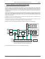
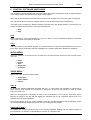
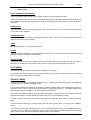
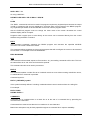
The Brick-2 videowall processor architecture is shown below.
The Brick consists of two independent video digitisers. The second video digitiser has a video buffer
memory to enable synchronisation with the first video digitiser. Video fields are streamed into the video
frame memory which can store up to four video fields. The output of the frame buffer is fed to the video
output processors which magnify the portion of the image to be displayed on the particular monitor in the
videowall array.
Various pixel switching and pixel intensity effects are provided in hardware. The video output processors
include colour wash registers to enable each monitor in the videowall array to display a different colour
wash. These colour washes block the display of video and can be dynamically switched to enable wipes
between wash and video.
In addition to a wash, each output processor can select each video input channel to enable both to be
displayed simultaneously on the videowall array.
The powerful on-board microcomputer can write directly into the video memory to enable on screen
messages and simple graphics to be displayed without any additional hardware.
Mux
S-Video
Decoder
B
Frame
Memory
Timebase
Correction
C-Video 1
C-Video 2
X-Y Window
BUS-A
Filter/Buffer
Encoder
Pixel Processing
S-Video
C-Video
Optional Expansion to 25 Outputs
Filter/Buffer
Decoder
A
BUS-B
Encoder
S-Video
BUS-A
Pixel Processing
C-Video 1
C-Video 2
Bus Multiplexor
Expansion Port
Bitmaps can also be downloaded and displayed to enable for example your company logo.
S-Video
C-Video
BUS-B
Zoom Tables
16
Video Outputs
Host RS232
CPU, Flash Memory and Timing Logic
JTAG FPGA
Programming
Interface
Loop RS232
Brick-2 Videowall Processor Architecture
Communications with the processor are via a simple RS-232 interface.
Copyright Media Technologies, 1999 – 2006
Page 3 of 61