1
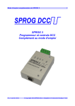
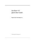
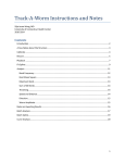
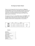
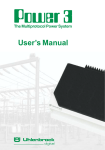
SBOOST II User Guide 1 SBOOST II DCC Booster User Guide Version 1.1 June 2015 © Copyright 2015SPROG DCC Ltd SBOOST II User Guide 2 Introduction SBOOST II is a DCC booster designed primarily intended for use with the SPROG II, but also useable with other DCC systems, to boost the track output current for driving a larger layout. Requirements Regulated DC Power Supply 12 – 20V, 3A Features Opto-isolated DCC input for electrical isolation between the layout and the command station DCC activity LED shows reception of valid DCC input Power LED flashes when programming track power is live DCC, Track and power connections by pluggable terminal blocks. Power out terminals for SPROG II. Specification/Operating Conditions Parameter DC Input supply voltage Minimum Typical 12V Vin supply current Output Load – Operating Layout Auto reverse detection delay Overload detection delay Overload cutout delay Maximum 20V Note 1 2.6 Note 2 Units 2.5 A V A 1.2 ms 3.2 ms 410 ms 1. If using the Power out terminals, the DC input supply must be limited in accordance with the equipment connected to the power out terminals. 2. The current capacity of the power supply must be greater than the 2.5A current limit of the SBOOST II. A suitable power supply is available from SPROG DCC Ltd or our dealer network. Version 1.1 June 2015 © Copyright 2015SPROG DCC Ltd SBOOST II User Guide 3 3. The DCC track voltage will be slightly less than the power supply voltage. Version 1.1 June 2015 © Copyright 2015SPROG DCC Ltd SBOOST II User Guide 4 DCC Parameters DCC signal input voltage DCC signal input current DCC signal input current DCC Input – Track Output Delay Minimum Typical 7 Maximum Units 20 10 Note 1 V mA 16.5 Note 2 1.6 mA µs 1. Vin 12V 2. Vin 18V LEDs Track LED DCC LED Off Track power off Flashing Moderately Quick Track power on Flashing quickly Short circuit Flashing slowly No DCC signal Flashing Quickly Valid DCC Signal Installation Connection to the SBOOST II is via 4-way pluggable terminal blocks as shown below. The following steps are required to install SBOOST II before you can use it for the first time: Version 1.1 June 2015 © Copyright 2015SPROG DCC Ltd SBOOST II User Guide 5 Connect to the Power Supply Connect to the Layout Connect to the Command Station Connect to the Power Supply Power supplies sold by SPROG DCC Ltd at the same time as an SBOOST II are supplied pre-wired to the pluggable terminal block. If using your own power supply, or the power supply provided by your dealer is not pre-wired, then it must be connected to the Power In terminals, observing the correct polarity. Connect to the Layout Connect the SBOOST II to the track using the track terminals “Tr A” and “Tr B” of the pluggable terminal block. Connect to the Command Station Connection to a SPROG II (version 2 and earlier) The pluggable terminal block is arranged to allow a straight forward connection to a SPROG II for both the DCC signal and to supply power to the SPROG II (See below), see the picture below. Connect the SBOOST II DCC inputs “In A” and “In B” to the SPROG II track outputs. Powering a SPROG II (all versions) There are two considerations to be taken into account when powering an SBOOST II and a SPROG II from the same power supply. The electrical isolation between the layout and command station (i.e. SPROG II) will no longer be effective. Version 1.1 June 2015 © Copyright 2015SPROG DCC Ltd SBOOST II User Guide 6 The SPROG II has a lower maximum supply voltage of 15V, compared to the SBOOST II maximum of 20V. When using an SBOOST II with a supply voltage greater than 15V special care must be taken. For SBOOST II supply voltages above 17V, a separate power source, of the correct voltage, must be used for the SPROG II. For SBOOST II supply voltages in the range 15 – 17V you can use a separate power supply or insert a string of 3 1N4001 (or similar) diodes in series with the +V connection to drop the voltage slightly. Connect the SBOOST II +V output to the SPROG II +V input. Connect the SBOOST II 0V output to the SPROG II 0 input. If the track output of the SPROG II is also powering a track power district then the power supply must be rated at least 3.5 Amps. See “Considerations When Daisy-chaining Boosters”, below. Connection to a SPROG 3 Follow the connection instructions for SPROG II. The SPROG 3 is rated for the same maximum voltage as the SBOOST II and can always use the same power supply. If electrical isolation is required between the layout and SPROG 3 then a separate, isolated, power supply must be used. If the track output of the SPROG 3 is also powering a track power district then the power supply must be rated at least 5 Amps. See “Considerations When Daisy-chaining Boosters”, below. Connection to Other Command Stations SBOOST II has an opto-isolated DCC input and can be connected to the DCC output of most DCC command stations and boosters. Multiple Power Districts Using SBOOST II If more than one SBOOST II is to be connected between the command station (e.g. one of the SPROG family) and the layout, to give multiple power districts, then care must be taken with both the DCC input connections and the track connections to ensure the same polarity at each SBOOST II. Connect all of the SBOOST II “In A” terminals together and connect to one output of the command station. Connect all of the SBOOST II “In B” terminals together and connect to the other output of the command station. Connect the “Tr A” and “Tr B” outputs to the layout in a consistent manner in Version 1.1 June 2015 © Copyright 2015SPROG DCC Ltd SBOOST II User Guide 7 each power district. E.g. connect “Tr A” to the left rail in each power district and connect “Tr B” to the right rail in each power district. BOTH rails MUST be gapped between power districts. The SBOOST II track outputs must only be connected to their own power district, i.e., there must be NO common wiring between power districts. If a single power supply is used to power more than one SBOOST II it must be rated to supply the maximum current to all SBOOST II simultaneously. E.g. for two SBOOST II the power supply must be rated at greater than 5 Amps. If separate power supplies are used to power multiple SBOOST II then they should all be of the same type and voltage rating. The 0V connections of all the SBOOST II must be connected together. This is sometimes referred to as a booster “home ground” connection. Considerations When Daisy-chaining Boosters If a booster A which powers a track power district A is connected to a booster B which powers a track district B then a short circuit in power district A will remove the DCC signal to the input of booster B. This will result in loss of power in power district B. For satisfactory DCC operation, daisy-chaining of boosters in this way is not recommended. Version 1.1 June 2015 © Copyright 2015SPROG DCC Ltd SBOOST II User Guide 8 Example 1 SPROG 3 (or SPROG II) driving multiple SBOOST II with common power supply. The power supply must be able to supply the full rated current (e.g., at least 5 Amp for 2 x SBOOST II). Power districts must be separated by isolation gaps in both rails. The SPROG 3 (or SPROG II) can be powered from one of the SBOOST II To further SBOOST Isolation Gap Power Version 1.1 June 2015 © Copyright 2015SPROG DCC Ltd SBOOST II User Guide 9 Example 2 SPROG 3 (or SPROG II) driving multiple SBOOST II with separate power supplies. Each power supply should be the same voltage. Each power supply must be able to supply the full rated current of the SBOOST II, i.e., at least 2.5 Amp. A common ground connection is required between the power supplies. Power districts must be separated by isolation gaps in both rails. The SPROG 3 (or SPROG II) can be powered from one of the SBOOST II. To further SBOOST Power Isolation Gap Power Version 1.1 June 2015 © Copyright 2015SPROG DCC Ltd SBOOST II User Guide 10 Example 3 SPROG 3, SPROG II or other booster and SBOOST II daisy-chained with common power supply. Using a SPROG 3 (or SPROG II or other booster) and SBOOST II in this way is not recommended. A short circuit in the SPROG 3 power district will affect the DCC signal to the SBOOST II, resulting in the loss of the DCC signal in the SBOOST II power district. The power supply must be able to supply the full rated current (i.e., at least 5 Amp for SPROG 3 plus SBOOST II). Power districts must be separated by isolation gaps in both rails. Isolation Gap Power Version 1.1 June 2015 © Copyright 2015SPROG DCC Ltd SBOOST II User Guide 11 Example 4 SPROG 3, SPROG II or other booster and SBOOST II with separate power supplies. Using a SPROG 3 (or SPROG II or other booster) and SBOOST II in this way is not recommended. A short circuit in the SPROG 3 power district will affect the DCC signal to the SBOOST II resulting in the loss of the DCC signal in the SBOOST II power district. Each power supply should be the same voltage. Each power supply must be able to supply the full rated current, at least 2.5 Amp. A common ground connection is required between the power supplies. Power districts must be separated by isolation gaps in both rails. Isolation Gap Power Version 1.1 June 2015 Power © Copyright 2015SPROG DCC Ltd SBOOST II User Guide 12 Auto-reverse Operation The SBOOST II can be configured for auto reverse operation, e.g., to supply power to a reverse loop or wye formation as a separate power district. To enable or disable auto-reverse operation you must open the casing of the SBOOST II and fit or remove a jumper link. To open the casing, prize the two halves apart by inserting a small flat bladed screwdriver in the slots and twisting gently, as shown below. Remove the small jumper from its parking location and re-fit it to bridge the pins of J1. Version 1.1 June 2015 © Copyright 2015SPROG DCC Ltd SBOOST II User Guide 13 When no jumper is fitted, auto-reverse operation is disabled. When a jumper link is fitted, auto-reverse operation is enabled. Auto-reverse operation must not be enabled in adjacent power districts. This may cause “thrashing” as both SBOOST II try to auto-reverse simultaneously. For UK customers, spare jumper links may be obtained from SPROG DCC Ltd on receipt of a stamped self-addressed envelope. They are also available from electronic component suppliers. Refit the casing by lining up and gently squeezing the two halves together. Version 1.1 June 2015 © Copyright 2015SPROG DCC Ltd SBOOST II User Guide 14 Troubleshooting Before reporting any problems please check the SPROG-DCC webpages for any bug reports or updates. Useful Links SPROG homepage http://www.sprog-dcc.co.uk for the latest information, updates, downloads, etc., for SBOOST II. SPROG DCC Yahoo group http://groups.yahoo.com/group/sprog-dcc for latest news and discussion. Version 1.1 June 2015 © Copyright 2015SPROG DCC Ltd