1
Networks without Barriers
SatLink VSAT User Guide
User Guide
Revision 14.1.1-2 – January 12th 2012
SatLink VSAT User Guide
©
®
™
Notice
Copyright 2006-2012, STM Group, Inc.
All rights reserved. Reproduction, adaptation or translation without prior written
permission is prohibited, except as allowed under the copyright laws.
The names of products (hardware and/or software) mentioned herein are regarded to be
the property of their respective companies, regardless of whether or not registration is
indicated.
The information in this publication is subject to change without notice. STM Group, Inc.
makes no warranty of any kind with regard to this material, including, but not limited to,
the implied warranties or merchantability and fitness for particular purposes. Moreover,
STM shall not be held liable for errors that may occur herein or for incidental or
consequential damage in connection with the furnishing, performance, or use of this
material.
Publication no. 101557
Rev 14.1.1-2
Copyright © 2006-2012 – STM Group, Inc.
Page 1 (182)
SatLink VSAT User Guide
Table of Contents
1.
INTRODUCTION .............................................................................................................................................. 5
1.1
1.2
1.3
ABOUT THIS USER GUIDE ............................................................................................................................. 6
INITIAL CONFIGURATION .............................................................................................................................. 6
SYMBOLS ...................................................................................................................................................... 7
2.
UNPACKING ..................................................................................................................................................... 8
3.
INSTALLATION ............................................................................................................................................... 9
3.1
3.2
3.3
3.4
3.5
4.
BEFORE INSTALLATION ................................................................................................................................ 9
SATLINK VSAT IDU FRONT AND REAR PANELS ......................................................................................... 9
IDU INSTALLATION .................................................................................................................................... 13
ODU INSTALLATION .................................................................................................................................. 14
INTERFACE CONNECTIONS .......................................................................................................................... 15
CONNECTING A PC TO THE SATLINK VSAT ........................................................................................ 17
4.1
4.2
WINDOWS 7 TCP/IP CONFIGURATION ........................................................................................................ 17
WINDOWS XP TCP/IP CONFIGURATION ..................................................................................................... 19
5.
USING THE SATLINK VSAT WEB INTERFACE ..................................................................................... 21
6.
SATLINK VSAT CONFIGURATION AND LINE-UP USING THE WEB INTERFACE ...................... 22
6.1
6.2
6.3
6.4
6.5
6.6
7.
LOG ON TO THE VSAT WEB INTERFACE .................................................................................................... 22
CONFIGURING VSAT PARAMETERS REQUIRED TO LOG ON TO THE HUB.................................................... 22
NAT CONFIGURATION USING THE WEB INTERFACE ................................................................................... 29
LINE-UP USING THE WEB INTERFACE ......................................................................................................... 29
TEST OF CONNECTION TO HUB ................................................................................................................... 33
PREPARE THE VSAT FOR NORMAL OPERATION ......................................................................................... 36
STATUS MONITORING USING THE SATLINK WEB INTERFACE .................................................... 39
7.1
7.2
7.3
7.4
8.
SATELLITE INTERFACE STATUS .................................................................................................................. 39
STATISTICS ................................................................................................................................................. 41
DEVICE STATUS .......................................................................................................................................... 43
DHCP SERVER STATUS .............................................................................................................................. 44
USING THE COMMAND LINE INTERFACE OF THE SATLINK VSAT ............................................. 45
8.1
8.2
8.3
8.4
9.
CLI USER ACCESS RIGHTS ......................................................................................................................... 45
ONLINE HELP ............................................................................................................................................. 45
LOGGING OF EVENTS .................................................................................................................................. 46
CLI COMMAND SUMMARY ......................................................................................................................... 47
SATLINK VSAT CONFIGURATION AND LINE-UP USING THE COMMAND LINE INTERFACE51
9.1
9.2
9.3
9.4
9.5
POWER ON AND LOG ON ............................................................................................................................ 51
INITIAL CONFIGURATION OF PARAMETERS................................................................................................. 53
LINE-UP ...................................................................................................................................................... 62
TEST OF CONNECTION TO THE HUB ............................................................................................................ 67
PREPARE THE VSAT FOR NORMAL OPERATION ......................................................................................... 69
10.
NETWORK ADDRESS TRANSLATION (NAT) ..................................................................................... 70
11.
QUALITY OF SERVICE ............................................................................................................................ 74
11.1
11.2
11.3
11.4
CONFIGURING QOS FOR THE RETURN LINK ................................................................................................ 75
CONFIGURING THE VSAT FOR VOIP .......................................................................................................... 77
CONFIGURING THE VSAT FOR VIDEO (VIC) .............................................................................................. 77
DSCP AND DIFFSERV ................................................................................................................................. 78
Publication no. 101557
Rev 14.1.1-2
Copyright 2006-2012 – STM Group, Inc.
Page 2 (182)
SatLink VSAT User Guide
12.
BANDWIDTH ON DEMAND .................................................................................................................... 80
13.
TRAFFIC INITIATED LOGON ................................................................................................................ 82
14.
HEADER COMPRESSION ........................................................................................................................ 83
14.1
14.2
ENABLING HEADER COMPRESSION............................................................................................................. 83
DISABLE HEADER COMPRESSION ............................................................................................................... 84
15.
ROUTING OF MULTICAST TRAFFIC .................................................................................................. 85
16.
UPDATING THE VSAT SW ...................................................................................................................... 86
16.1
16.2
16.3
17.
17.1
17.2
17.3
17.4
18.
18.1
18.2
18.3
18.4
18.5
18.6
18.7
19.
19.1
19.2
19.3
19.4
19.5
AUTOMATIC SOFTWARE UPDATE ............................................................................................................... 87
MANUAL SOFTWARE UPDATE .................................................................................................................... 88
RESTORING THE BACKUP SOFTWARE ......................................................................................................... 89
SATLINK AND DVB-S2 ............................................................................................................................. 90
DVB-S2 MODULATION .............................................................................................................................. 90
DVB-S2 CODING ....................................................................................................................................... 90
DVB-S2 CODING AND MODULATION CONTROL MODES ............................................................................ 92
DVB-S2 CONFIGURATION FOR 1910 IDUS WITH THE SATLINK 100 PLUG-IN CARD .................................. 93
SOFTWARE OPTIONS .............................................................................................................................. 95
GENERIC ROUTING ENCAPSULATION (GRE) AND IP TUNNELING............................................................... 96
TCP PERFORMANCE ENHANCING PROXY (PEP) ......................................................................................... 97
HTTP ACCELERATION (HTTPA) ............................................................................................................... 99
RETURN LINK ACCESS CONTROL (RAC) .................................................................................................. 102
VLAN EXTENSION (802.1Q) .................................................................................................................... 104
ETHERNET USER PRIORITY (802.1P/D) ..................................................................................................... 105
DVB-S2 16-APSK ................................................................................................................................... 106
EXTENSIONS FOR MOBILE VSATS ................................................................................................... 108
TRANSMIT INHIBIT FUNCTION .................................................................................................................. 108
GPS INTERFACE ....................................................................................................................................... 110
RX LOCK SIGNAL ..................................................................................................................................... 111
OPTIMIZING THE MOBILE VSAT FOR RECOVERING CONTACT WITH THE NETWORK AFTER BLOCKINGS . 111
MOBILE VSAT LAN INTERFACE TO MOBILE ANTENNA CONTROLLER .................................................... 112
20.
MESH VSATS ............................................................................................................................................ 118
21.
DEFINITIONS, ACRONYMS AND ABBREVIATIONS ...................................................................... 123
22.
REFERENCES ........................................................................................................................................... 125
APPENDIX A.
ACCESSING THE COMMAND LINE INTERFACE VIA SERIAL CONSOLE PORT 126
APPENDIX B.
TFTP SERVER ......................................................................................................................... 129
APPENDIX C.
TELNET CLIENT .................................................................................................................... 130
APPENDIX D.
TESTING THE CONNECTION TO THE VSAT ................................................................. 131
APPENDIX E.
MANAGEMENT VIA SNMP ................................................................................................. 140
APPENDIX F.
ODU INSTALLATION ............................................................................................................ 148
APPENDIX G.
SATLINK 403X: INTERFACING VSAT RX/TX ANTENNAS .......................................... 154
Publication no. 101557
Rev 14.1.1-2
Copyright 2006-2012 – STM Group, Inc.
Page 3 (182)
SatLink VSAT User Guide
APPENDIX H. MANUAL CONFIGURATION OF PARAMETERS NORMALLY CONFIGURED
AUTOMATICALLY FROM THE HUB .............................................................................................................. 157
APPENDIX I.
IDU POWER CALIBRATION AND P1DB CONFIGURATION WITH BUCS OTHER
THAN THE SATLINK 403X ................................................................................................................................. 161
APPENDIX J.
THE BOOT SW ........................................................................................................................ 164
APPENDIX K.
TROUBLESHOOTING ........................................................................................................... 165
APPENDIX L.
COMPLIANCE ........................................................................................................................ 177
APPENDIX M.
STANDARDIZATION OF TIMING COMPENSATION................................................ 179
APPENDIX N.
RECEIVER AND TRANSMITTER AUTOSTART ............................................................. 180
APPENDIX O.
ACCESSING THE FORWARD LINK SIGNALING ........................................................... 181
Publication no. 101557
Rev 14.1.1-2
Copyright 2006-2012 – STM Group, Inc.
Page 4 (182)
SatLink VSAT User Guide
1. Introduction
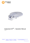
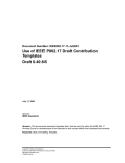
The SatLink 1000, 1910, 2000, and 2900 are the indoor units (IDUs) of the SatLink family of DVB-RCS
VSATs. They perform several functions: they are satellite modems (at Layer 1); they handle data link
layer processing (at Layer 2) for both satellite and LAN communications; and they act as IP routers and
DHCP servers (at Layer 3). All SatLink IDUs provide an Ethernet 10/100 LAN interface for one or more
PCs to engage in two-way communication via a SatLink (or any DVB-RCS compliant) satellite network.
Figure 1: SatLink 1000, 1910, 2000, and 2900 Indoor Units (IDUs)
Figure 2: SatLink Outdoor Unit (ODU)
Publication no. 101557
Rev 14.1.1-2
Copyright 2006-2012 – STM Group, Inc.
Page 5 (182)
SatLink VSAT User Guide
1.1
About this User Guide
This User Guide covers the installation and operation of the SatLink 1000/1910/2000/2900, commonly
also referred to as the indoor unit (IDU) of the DVB-RCS VSAT, together with the accompanying
outdoor unit (ODU) equipment. It is intended for DVB professionals, such as service providers and
installers. Therefore, it does not contain information for non-professional users, such as given in the user
manuals of consumer electronic products. The information given pertains to the following STM software
(SW) and hardware (HW) versions and releases:
SatLink IDU Software
STM SatLink Boot loader, P/N 101225, SW build 1.8.0.2 and later
STM SatLink Boot loader, P/N 106267, version 9.0.0 and later
STM SatLink Boot loader, P/N 120044 , Revision 14.0.0 and later
STM SatLink Boot loader, P/N 120511, Revision 14.1.0 and later
STM SatLink DVB-RCS VSAT Software, P/N 120208, version 14.1.0 and later
SatLink VSAT IDU Hardware models
STM SatLink 100 DVB-S2 Plug-in card for SatLink 1910, P/N 107261
STM SatLink 1000, P/N 103346
STM SatLink 1910, P/N 103798
STM SatLink 2000, P/N 120033
STM SatLink 2900, P/N 120510
Ku-band Equipment
Transceivers
STM SatLink 4033, P/N 104804
STM SatLink 4035, P/N 106546
1.2
Initial Configuration
The VSAT IDU must be configured before it can communicate via the satellite to and from the network
Hub. The parameters to be configured are explained in section 6.2.
The configuration of the VSAT IDU can be carried out using the following configuration tools:
Web-interface (basic configuration only)
Command Line Interface (CLI)
Via RS232/Terminal emulator (e.g. HyperTerminal)
Telnet
SNMP
The SatLink VSAT web interface is used as the main interface for initial configuration of the VSAT
parameters and is presented in section 6. The status monitoring of the VSAT using a web interface is
presented in section 7. Configuration via CLI is presented in section 9 and management via SNMP is
presented in Appendix E. The Web interface can be used for most common configuration tasks, while
advanced configuration is only available via SNMP and CLI.
Publication no. 101557
Rev 14.1.1-2
Copyright 2006-2012 – STM Group, Inc.
Page 6 (182)
SatLink VSAT User Guide
1.3
Symbols
NOTE
Additional information that the reader should pay special attention to.
WARNING
System malfunction may occur if the warning information is violated.
Publication no. 101557
Rev 14.1.1-2
Copyright 2006-2012 – STM Group, Inc.
Page 7 (182)
SatLink VSAT User Guide
2. Unpacking
Check that the following items are in the box received and then unpack.
SatLink 1000, 1910, 2000, or 2900
Stand for vertical placement (SatLink 1000 only)
AC adapter (SatLink 1000/2000 only )
Power cord
Brackets for 19‖ rack mounting (SatLink 1910 and SatLink 2900 only)
Publication no. 101557
Rev 14.1.1-2
Copyright 2006-2012 – STM Group, Inc.
Page 8 (182)
SatLink VSAT User Guide
3. Installation
3.1
Before Installation
3.1.1 Safety
Follow these guidelines to ensure general safety:
Always comply with national and local electrical codes.
Keep the installation area clear and dust free during and after installation.
Keep tools and all components away from walking areas.
Do not wear loose clothing, jewelry (including rings and chains), or other items that might get caught
on the IDU, the ODU, or the interconnecting cables.
Do not work on the system or connect or disconnect cables during lightning storms.
Follow these guidelines when working with electrical equipment:
Disconnect all power and external cables before installing or removing a SatLink VSAT IDU.
Do not work alone when potentially hazardous conditions exist.
Never assume that power has been disconnected from a circuit; always check.
Do not act in any way that creates a potential hazard to people or makes the equipment unsafe.
Never install equipment that appears damaged.
Carefully examine your work area for possible hazards such as moist floors, unearthed power
extension cables and missing protective earths.
Should an electrical accident occur:
Be cautious – do not become a victim yourself
Turn off electrical power to the system.
If possible, send another person to get medical aid. Otherwise, assess the condition of the victim and
then call for help.
Determine if the victim needs artificial respiration or external cardiac compressions; then take
appropriate action.
3.1.2 Site Requirements
The VSAT IDU should be connected to 110/240 VAC, 50-60Hz power.
3.2
SatLink VSAT IDU Front and Rear Panels
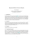
3.2.1 SatLink 2000 Front and Rear Panel
Figure 3 : SatLink 2000 Front Panel
Publication no. 101557
Rev 14.1.1-2
Copyright 2006-2012 – STM Group, Inc.
Page 9 (182)
SatLink VSAT User Guide
LED
Yellow: lights steadily when connected to the power supply and unit is powered. Flashes
when loading software.
Red: lights steadily when an error event occurs and during reboot.
Power
Error
Satellite
Receive
Transmit
Ethernet
Color: indicates
Link/Act
Status
White: flashes when the receiver is searching for the carrier.
Lights steadily when receiver is on and functioning properly.
Flashes when IP packets are received from the Satellite Interface (the Hub).
White: flashes rapidly when a continuous wave (CW) is transmitted.
Lights steadily when the VSAT is logged on to the DVB-RCS Hub.
Flashes when IP packets are transmitted to the Satellite Interface (the Hub).
White: lights steadily when Ethernet connectivity is OK.
Flashes slowly when Ethernet packets are transferred via the Ethernet interface.
For future use
Table 1: SatLink 2000 Front Panel LEDs
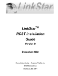
Figure 4 : SatLink 2000 Rear Panel
Item
Power Connector
Ethernet
Connector
COM1 Connector
RX coaxial jack
TX coaxial jack
Description
Connector for cable to the 24 V DC power transformer (external power supply provided
with STM SatLink 2000 VSAT)
RJ45 connector for IP traffic to connect to a PC, Ethernet switch, IP router etc. 10BASE-T
or 100BASE-T modes is detected automatically.
Nine pin connector for connecting CLI interface to a computer‘s DB-9 serial interface.
Coaxial 75 F-type jack for the cable to the LNB.
Coaxial 75 F-type jack for the cable to the BUC.
Table 2: SatLink 2000 Rear Panel Description
3.2.2 SatLink 1000 Front and Rear Panel
Figure 5: SatLink 1000 Front Panel
Publication no. 101557
Rev 14.1.1-2
Copyright 2006-2012 – STM Group, Inc.
Page 10 (182)
SatLink VSAT User Guide
LED
White: lights steadily when power switch is on and unit has power. Flashes when loading
software.
Red: lights steadily when an error event occurs and during reboot.
Power
Error
Satellite
Receive
Transmit
Ethernet
Color: indicates
Link/Act
White: flashes when the receiver is searching for the carrier.
Lights steadily when receiver is on and functioning properly.
Flashes when IP packets are received from the Satellite Interface (the Hub).
White: flashes rapidly when a continuous wave (CW) is transmitted.
Lights steadily when the VSAT is logged on to the DVB-RCS Hub.
Flashes when IP packets are transmitted to the Satellite Interface (the Hub).
White: lights steadily when Ethernet connectivity is OK.
Flashes slowly when Ethernet packets are transferred via the Ethernet interface.
Table 3: SatLink 1000 Front Panel LEDs
Figure 6: SatLink 1000 Rear Panel
Item
On/off switch
Power Connector
Ethernet
Connector
COM1 Connector
RX coaxial jack
TX coaxial jack
Description
Power on (1) or off (0).
Connector for cable to the 24 V DC power transformer (external power supply provided
with SatLink 1000 VSAT)
RJ45 connector for IP traffic to connect to a PC, Ethernet switch, IP router, etc. 10BASET or 100BASE-T modes are detected automatically.
Nine pin connector for connecting CLI interface to a computer‘s DB-9 serial interface.
Coaxial 75 F-type jack for the cable to the LNB.
Coaxial 75 F-type jack for the cable to the BUC.
Table 4: SatLink 1000 Rear Panel Description
3.2.3 SatLink 1910 Front and Rear Panel
Figure 7: SatLink 1910 Front Panel
Publication no. 101557
Rev 14.1.1-2
Copyright 2006-2012 – STM Group, Inc.
Page 11 (182)
SatLink VSAT User Guide
LED
Color: indicates
Power
White: lights steadily when power switch is on and unit is powered. Flashes when
loading software.
Error
Red: lights steadily when an error event occurs and during reboot.
Satellite
Ethernet
Receive
White: flashes when the receiver is searching for the carrier.
Lights steadily when receiver is on and functioning properly.
Flashes when IP packets are received from the Satellite Interface (the Hub).
Transmit
White: flashes rapidly when a continuous wave (CW) is transmitted.
Lights steadily when the VSAT is logged on to the DVB-RCS Hub.
Flashes when IP packets are transmitted to the Satellite Interface (the Hub).
White: lights steadily when Ethernet connectivity is OK.
Flashes slowly when Ethernet packets are transferred via the Ethernet interface.
Link/Act
Table 5: SatLink 1910 Front Panel LEDs
Figure 8: SatLink 1910 Rear Panel
Item
On/Off switch
Power Connector
Ethernet Connector
COM1 Connector
Cover for Accessory Card
RX coaxial jack
TX coaxial jack
Description
Power on (1) or off (0).
Standard recessed plug for 110-240VAC power cord.
RJ45 connector for IP traffic to connect to a PC, Ethernet switch, IP router, etc.
10BASE-T or 100BASE-T mode is detected automatically.
Nine pin connector for connecting CLI interface to a computer‘s DB-9 serial
interface.
Not used.
Coaxial 75 F-type jack for the cable to the LNB.
Coaxial 75 F-type jack for the cable to the BUC.
Table 6: Description of SatLink 1910 Rear Panel
3.2.4 SatLink 2900 Front and Rear Panel
Figure 9: SatLink 2900 Front Panel
Publication no. 101557
Rev 14.1.1-2
Copyright 2006-2012 – STM Group, Inc.
Page 12 (182)
SatLink VSAT User Guide
LED
Color: indicates
Power
White: lights steadily when power switch is on and unit is powered. Flashes when
loading software.
Error
Red: lights steadily when an error event occurs and during reboot.
Satellite
Ethernet
Receive
White: flashes when the receiver is searching for the carrier.
Lights steadily when receiver is on and functioning properly.
Flashes when IP packets are received from the Satellite Interface (the Hub).
Transmit
White: flashes rapidly when a continuous wave (CW) is transmitted.
Lights steadily when the VSAT is logged on to the DVB-RCS Hub.
Flashes when IP packets are transmitted to the Satellite Interface (the Hub).
White: lights steadily when Ethernet connectivity is OK.
Flashes slowly when Ethernet packets are transferred via the Ethernet interface.
Link/Act
Table 7: SatLink 2900 Front Panel LEDs
Figure 10: SatLink 2900 Rear Panel
Item
On/Off switch
Power Connector
Ethernet Connector 1
Ethernet Connector 2
USB Port
DC Power Connector
COM1 Connector
Cover for Accessory Card
J1
RX coaxial jack
TX coaxial jack
Description
Power on (1) or off (0).
Standard recessed plug for 110-240VAC power cord.
RJ45 connector for IP traffic to connect to a PC, Ethernet switch, IP router etc.
10BASE-T, 100BASE-T or 1000BASE-T mode is detected automatically.
Not used.
Not used.
Connector for alternative 24VDC (19-36VDC) power supply. Typically used when
powered from solar panels.
Nine pin connector for connecting CLI interface to a computer‘s DB-9 serial
interface.
Not used.
Digital I/O used for Mobile applications Please refer to section 19.1.2 for more
information.
Coaxial 75 F-type jack for the cable to the LNB.
Coaxial 75 F-type jack for the cable to the BUC.
Table 8: SatLink 2900 Rear Panel
3.3
IDU Installation
3.3.1 On Desktop or Shelf
Place the VSAT IDU on a flat, stable surface, such as a desktop or shelf, close to the PC or network
device to which it will be connected. Keep its top, bottom, and all sides unobstructed to ensure free
airflow. Rubber feet on the bottom provide adequate clearance. Ensure that there is at least 10 cm
clearance at the back to allow room for cable connections.
Publication no. 101557
Rev 14.1.1-2
Copyright 2006-2012 – STM Group, Inc.
Page 13 (182)
SatLink VSAT User Guide
3.3.2 In Rack
The rack or cabinet should be properly secured to prevent tipping. Equipment that is
installed in a rack or cabinet should be mounted as low as possible, with the heaviest units
lower down, and lighter units toward the top.
Precautions:
Ensure that the power circuits are properly grounded and use the power cord supplied with the
SatLink VSAT IDU to connect it to the power outlet.
If your installation requires a different power cord than the one supplied, ensure that the cord used is
certified as indicated by the stamped or embossed logo of the electrical safety authority in your
country.
If the on/off switch on the back panel is difficult to reach when the unit is fitted in the rack, ensure
that the power outlet into which it is plugged can be reached so it may be unplugged if necessary.
Ensure that the unit does not overload the power circuit, wiring, or over-current protection. To
determine the possibility of overloading the supply circuits, add together the amperage ratings of all
devices installed on the same circuit as the VSAT IDU and compare the total with the rating limit for
the circuit. The maximum amperage ratings are usually printed on units near their power connectors.
Do not install the VSAT IDU in a location where the operating ambient temperature may exceed
45°C.
Ensure that the airflow around the sides and back of the SatLink VSAT IDU is not restricted.
The SatLink 1900/1901/1910/2900 can be mounted in any EIA-standard 19-inch telecommunications
rack or cabinet. The STM SatLink 1000 and 2000 need to be placed on a shelf if either is to be placed in a
rack.
Use a Torx screwdriver and attach the mounting brackets to the router with the screws supplied. Hold the
unit securely, brackets attached, and move it vertically until the rack holes line up with the bracket
notches, then insert and tighten the four screws holding the brackets to the rack.
Figure 11: Rack Mounting
3.4
ODU Installation
Install the ODU as described in Appendix F, reference [1] and the antenna installation manual. When
installing the SatLink 403x transceiver, please check Table 22 in Appendix G to determine whether an
adapter is required to interface the antenna feed horn.
Publication no. 101557
Rev 14.1.1-2
Copyright 2006-2012 – STM Group, Inc.
Page 14 (182)
SatLink VSAT User Guide
3.5
Interface Connections
3.5.1 RX/TX cables between IDU and ODU
The coaxial cables from the ODU are connected to the type F coaxial jacks on the back panel of the
VSAT IDU.
Connect one coaxial cable from the ODU TX module input to the jack marked TX.
Connect one coaxial cable from the LNB to the port marked RX on the back panel.
Use only 75 Ω coaxial cables fitted with type F plugs for the RX and TX cables. Make sure
that the connectors are waterproof, such as the F-connector RG6 Compression type from
Cablecon (www.cablecon.dk), article no. 99909446
ODU TX and RX connectors must always be protected with vulcanizing tape after the
coaxial cables to the BUC and LNB are connected as shown in Figure 12.
Figure 12 : TX and RX Connectors with Vulcanizing Tape
Do not connect and disconnect the coaxial cables with power connected to the VSAT IDU.
Hint
Use different color marking on the TX and RX coaxial cables to eliminate likelihood of
interchanging the RX and TX coaxial cables.
Publication no. 101557
Rev 14.1.1-2
Copyright 2006-2012 – STM Group, Inc.
Page 15 (182)
SatLink VSAT User Guide
3.5.2 Ethernet connection to a Local Area Network (LAN)
The VSAT IDU may be connected to a single PC or to a network via the RJ-45 Ethernet jack on the back
panel.
Plug one end of the Ethernet cable into the RJ-45 jack on the back panel.
Plug the other end of the Ethernet cable into the RJ-45 jack a Local Area Network (LAN) device,
such as an Ethernet hub, switch, or router, according to its manufacturer‘s instructions.
The SatLink VSAT will auto-detect if Ethernet HUB or NODE mode is used and will automatically chose
the correct mode; hence there is no need to use a cross-over Ethernet cable for direct connections to PCs.
3.5.3 Power Connection
The SatLink 1910 and 2900 models have internal power supply and consequently are connected directly
to a 110/230 VAC 50/60Hz outlet using a standard 230 VAC power cord.
3.5.4 Power supply
The SatLink 1000 and 2000 have an external power supply that is connected to a 110/240 VAC 50/60Hz
outlet using a standard power cord.
The SatLink 1000 and 2000 must only be connected to the external power supply that is
approved by STM, PN 104170 (LEI-S2425D/Adapter Technology, Model No. STD-2425).
Use of another power supply will void warranty.
Publication no. 101557
Rev 14.1.1-2
Copyright 2006-2012 – STM Group, Inc.
Page 16 (182)
SatLink VSAT User Guide
4. Connecting a PC to the SatLink VSAT
After installation as described in Chapter 3 is carried out, the VSAT IDU is ready to be powered on.
4.1
Windows 7 TCP/IP Configuration
Verify that the TCP/IP configuration is correct for PCs connected to the LAN that are to be used for your
SatLink VSAT. Click on the Start button in Windows 7, select Control Panel, and then click Network and
Sharing Center. Click Change Adapter Settings and right-click on the relevant Local Area Connection and
select Properties. A new window showing the Network Connection Properties will pop up. In the
Networking submenu of this window, scroll down, select Internet Protocol Version 4 (TCP/IPv4) and
then click the Properties button shown in Figure 13. Then configure the PC client to obtain the IP address
automatically from the VSAT IDU (section 4.1.1) or configure the PC with a static IP address (section
4.1.2).
Figure 13: Windows 7 Menu for Configuring the Client TCP/IP Configuration
Publication no. 101557
Rev 14.1.1-2
Copyright 2006-2012 – STM Group, Inc.
Page 17 (182)
SatLink VSAT User Guide
4.1.1 Dynamic IP Configuration of PCs Connected to the VSAT LAN
By default, the DHCP server in the SatLink VSAT is enabled, and when the VSAT is powered on, all PCs
connected to the VSAT LAN can automatically retrieve their IP configuration from the DHCP server. The
user should verify that the Windows clients are configured to obtain an IP address and DNS server
address automatically. Figure 14 shows the correct Windows 7 configuration when the DHCP server is
enabled in the VSAT.
Figure 14: Windows 7 TCP/IP Setting when DHCP Server is Enabled in the VSAT
From an MS-DOS window, the user may type ipconfig /all command to verify that the computer has
received correct configuration parameters from the DHCP server, such as IP address, subnet mask, default
Gateway, DNS servers, and lease time.
Figure 15: ipconfig /all Printout from an MS-DOS Window
Publication no. 101557
Rev 14.1.1-2
Copyright 2006-2012 – STM Group, Inc.
Page 18 (182)
SatLink VSAT User Guide
4.1.2 Static IP Configuration of PCs Connected to the VSAT LAN
When the DHCP server in the SatLink VSAT is disabled, all PCs attached to the VSAT LAN must be
configured with static IP addresses that are within the address range of the VSAT subnet. The IP
configuration parameters to use for PCs connected to the VSAT LAN are supplied from the system
operator or service provider. Configure the IP address, Subnet mask, Default gateway, Preferred DNS
server, and, optionally, the Alternate DNS server as shown in Figure 16.
Ensure that the actual IP addresses supplied by the system operator/service provider are
configured and not the IP addresses in the example figure.
Figure 16: Windows 7 TCP/IP Setting when DHCP Server is Disabled in the VSAT
Example:
A host may have the following configuration: IP address 10.201.0.10, Subnet mask 255.255.255.0 and
default gateway 102.201.0.9, where the IP address of the default gateway should be the IP address of the
VSAT LAN interface.
4.2
Windows XP TCP/IP Configuration
Verify that the TCP/IP configuration is correct for PCs connected to the LAN you plan to use for your
SatLink VSAT. Click on the Start button in Windows, click Control Panel and then open Network
Connections. Right-click on the relevant Local Area Connection and select Properties. A new window
showing the Network Connection Properties will pop up. In the General submenu of this window, scroll
down, select Internet Protocol (TCP/IP) and then click the Properties button shown in Figure 17. Then
configure the PC client to obtain the IP address automatically from the VSAT IDU (section 4.1.1 ) or
configure the PC with a static IP address (section 4.1.2).
Publication no. 101557
Rev 14.1.1-2
Copyright 2006-2012 – STM Group, Inc.
Page 19 (182)
SatLink VSAT User Guide
Figure 17: Windows XP Menu for Configuring the Client TCP/IP Configuration.
Note: The procedure for Dynamic and Static IP configuration of PCs connected to the VSAT LAN using
Windows XP are the same as described in section 4.1.1 and section 4.1.2, respectively.
Publication no. 101557
Rev 14.1.1-2
Copyright 2006-2012 – STM Group, Inc.
Page 20 (182)
SatLink VSAT User Guide
5. Using the SatLink VSAT Web Interface
The SatLink VSAT Web interface supports managing the most common configuration parameters and
viewing the status of the VSAT. The web browser currently supported is Microsoft Internet Explorer, but
other browsers, like Firefox and Opera, typically work fine as well. The functions available via the web
interface are:
Configuring the most commonly used satellite interface parameters
Configuring the most commonly used IP parameters
Return Link line-up procedure
Viewing status information for the satellite interface
Viewing traffic statistics
Viewing device information
Viewing status of the DHCP server
Viewing Event log information
Advanced functions, such as adding SW licenses, configuring GRE tunnels, downloading software
updates manually, configuring automatic software updates, configuring system information, adding users
and changing a user's password, configuring SNMP access, adding manual IP routes, etc., are only
available from the CLI via Telnet or the RS-232 port.
To manage the SatLink VSAT via the web interface, start the web browser and type in the IP address of
the VSAT in the address field as shown in Figure 18. The factory default IP address of the SatLink VSAT
is 192.168.0.1. Use the VSAT‘s Satellite Interface (DVB) IP address when connecting to the VSAT over
the satellite link (from the Hub), and the VSAT‘s LAN (Ethernet) IP address when connecting to the
VSAT from the local LAN. Then enter the username and password to log on to the VSAT.
Figure 18: Connecting to the Web Interface
Publication no. 101557
Rev 14.1.1-2
Copyright 2006-2012 – STM Group, Inc.
Page 21 (182)
SatLink VSAT User Guide
6. SatLink VSAT Configuration and Line-up Using the Web
Interface
Follow all the procedures mentioned below when installing the SatLink VSAT and lining up the ODU
using the Web interface. Please see section 7 for SatLink VSAT status monitoring using the web
interface.
6.1
Log On to the VSAT Web Interface
1) Start the web browser and type in the IP address of the VSAT in the address field.
2) Login with username install and factory default password dvbrcs. Click the OK button.
Username: install
Password: dvbrcs
Figure 19: Log on Page
6.2
Configuring VSAT Parameters Required to Log on to the Hub
The SatLink VSAT Web interface is used to configure a number of parameters before the VSAT can
acquire the Forward Link and communicate with the Hub via the satellite connection. A default
configuration specifying most of these parameters is pre-loaded on each VSAT, either in the factory or by
the service provider before installation. The following configuration parameters are typically to be
configured using the VSAT Web interface:
DVB-S2 Reception parameters
VSAT GPS Position
Other parameters are typically configured automatically from the Hub when the VSAT logs on for the
first time. When ODUs other than the SatLink 403x transceiver are used or if the Hub operator does not
use automatic VSAT configuration, then additional VSAT parameters might have to be configured during
installation.
Publication no. 101557
Rev 14.1.1-2
Copyright 2006-2012 – STM Group, Inc.
Page 22 (182)
SatLink VSAT User Guide
6.2.1 Receiver Parameter Configuration
The VSAT is normally pre-configured to be used together with the SatLink 403x transceiver. But it is
possible to configure the VSAT to operate together with transceivers other than the SatLink 403x. The list
of LNBs that can be used with the VSAT are listed in Table 11
1) Click on the Configuration Satellite option in the SatLink VSAT home page.
Figure 20: Configuring Receiver Parameters for Fixed VSAT
Publication no. 101557
Rev 14.1.1-2
Copyright 2006-2012 – STM Group, Inc.
Page 23 (182)
SatLink VSAT User Guide
2) Configure the Receiver parameters as shown in the following table:
Parameter
Auto Start
LNB Type
Entry
Description
On
Off
Specific for the receiver. When set to "On" the VSAT will automatically acquire the
Forward Link. It is recommended to always set this to ―On‖ for normal operation. Please
always restart the VSAT after saving configuration when having set auto start to ―On‖.
Specifies the LNB type with which the VSAT is configured.
The web interface allows the configuration of two Forward Link entries for fixed
VSATs:
Primary: corresponds to ―Index 0‖ of CLI configuration
Secondary: corresponds to ―Index 1‖ of CLI configuration
The primary entry has higher priority than the secondary entry so the Forward Link
search will start with the primary entry.
Symbol Rate (Msps)
Frequency (GHz)
Mode
PopId
Enable
Publication no. 101557
Rev 14.1.1-2
If the VSAT has a ―Mobile‖ license the web interface allows the configuration of up to
10 Forward Link entries with up to 10 different priorities [0 – 9].
The Forward Link symbol rate in Msps.
Forward Link frequency [kHz].
Enter the valid modes:
DVB-S
DVB-S2
Population ID to use for Forward Link acquisition. The VSAT will select
which group in the DVB-RCS system it belongs to based on the configured population
ID. The population ID to be used is assigned by the Hub Operator.
Enable the table entry.
Copyright 2006-2012 – STM Group, Inc.
Page 24 (182)
SatLink VSAT User Guide
3) Click the Save button to save the configuration.
4) Click Start button to start the receiver manually (Only required with Autostart mode ―off‖).
6.2.2 Transmitter Parameter Configuration
The VSAT is normally pre-configured to be used together with the SatLink 403x transceiver. But it is
possible to configure the VSAT to operate together with transmitters other than the SatLink 403x. The
valid ODU transmitters (BUC) used with the VSAT are listed in Table 9.
1) Click on the Configuration Satellite option in the SatLink VSAT home page.
Figure 21: Configuring Transmitter Parameters
Publication no. 101557
Rev 14.1.1-2
Copyright 2006-2012 – STM Group, Inc.
Page 25 (182)
SatLink VSAT User Guide
2) Configure the Transmitter parameters as shown in the following table.
Parameter
Auto Start
EIRP (dBW)
Timeout (min)
IDU OutPow (dBm)
BUC
Antenna
Description
ON
Off
Traffic
Specific for the transmitter. When set to "traffic", the VSAT will log on to the Hub when
it has traffic to send. After a configurable time (given by Timeout) without any traffic to
send, the VSAT will automatically log off.
Specifies the emitted power level. Only used for a SatLink 403x ODU and not relevant
for a 3rd party BUC.
Idle time before the VSAT automatically logs off when the Autostart mode is set to
"traffic".
Only used for 3rd party BUCs, as the IDU output power is set automatically when using
a SatLink 403x ODU.
Specifies the BUC type or transceiver type with which the VSAT is equipped. The valid
ODU transmitters (BUCs) are listed in Table 9.
Specifies the antenna type with which the VSAT is equipped. The correct antenna type is
required to correctly compute EIRP used for the automatic power calibration of the
SatLink 403x transceiver. The valid ODU receivers (LNB) are listed in Table 11.
If the ODU transmitter type or LNB type has been changed, the VSAT must be restarted to
activate the new configuration (press the Restart button after saving the configuration).
3) Click the Save button to save the configuration.
4) Click Start button to start the transmitter manually (only required with Autostart mode ―off‖).
6.2.3 VSAT Positioning
The Operator must specify the geographical position of the VSAT to enable the VSAT to log on to the
network. In order to calculate the delay to the satellite correctly for the logon burst, the VSAT must be
configured with its own geographical position. Find the position of the location where installing the
VSAT using a standard GPS.
The VSAT position is entered in the below format:
degrees, minutes, seconds, and direction
Publication no. 101557
Rev 14.1.1-2
Copyright 2006-2012 – STM Group, Inc.
Page 26 (182)
SatLink VSAT User Guide
1) Click on the Configuration Satellite option in the SatLink VSAT home page.
Figure 22: VSAT Positioning
2) Configure the VSAT positioning parameters as shown in the following table.
Parameter
Latitude
Longitude
Altitude
Description
Enter the latitude (deg, min, sec and direction).
Enter the longitude (deg, min, sec and direction)
Enter the altitude (meters)
3) Click the Save button to save the configuration.
Publication no. 101557
Rev 14.1.1-2
Copyright 2006-2012 – STM Group, Inc.
Page 27 (182)
SatLink VSAT User Guide
6.2.4 IP Address Configuration
1) The VSAT web interface is used to configure the IP addresses and netmasks of the VSAT's LAN,
Management and Virtual (Vir1-eth0) interfaces. The Web interface is also used for LAN DHCP
server, DNS, NAT, and PEP configuration.
Click on the Configuration IP option in the SatLink VSAT home page.
Figure 23: IP Configuration – LAN, Management, and Virtual Interfaces
2) Enter the valid IP address and Netmask for the LAN, Management, and Virtual (Vir1-eth0) interfaces.
3) Enable / Disable the DHCP server.
The DHCP server can be enabled only for one interface (LAN or Virtual).
When enabled, the DHCP server will automatically allocate IP addresses in the VSAT LAN (or
Virtual) Interface subnet except the VSAT's own IP LAN (or Virtual) address and addresses excluded
manually.
4) Set the lease time for an IP address allocated to a host on the LAN (or Virtual) subnet.
5) Specify the number of IP addresses to be excluded from the available range of addresses defined by
the VSAT LAN (or Virtual) subnet. The excluded range of IP addresses will be the upper range of the
LAN (or Virtual) subnet.
6) Enter the IP address for the primary and secondary DNS servers to be used by the hosts on the VSAT
LAN (or Virtual) subnet.
Publication no. 101557
Rev 14.1.1-2
Copyright 2006-2012 – STM Group, Inc.
Page 28 (182)
SatLink VSAT User Guide
7) Enable / Disable NAT (dynamic NAPT) for the VSAT.
When enabled, enter the NAT Global Address.
8) Enable / Disable the TCP and HTTP acceleration.
9) Click the Save button to save the configuration.
6.3
NAT Configuration using the Web Interface
Set up the NAT Configuration as shown below.
Figure 24: NAT Configuration
Parameter
Global Address
Local Address
Global Port
Local Port
Port Range
6.4
Description
Enter Global Address
Enter Local Address
Enter Global Port nr.
Enter Local Port nr.
Enter wanted Port Range.
Line-up Using the Web Interface
Perform antenna and ODU installation and alignment as described in Appendix F and the initial
parameter configuration described in section 6.2 before proceeding with the line-up procedures described
here.
6.4.1 Antenna Line-up
Set the alignment of the antenna to optimize the receive SNR. The RX SNR displayed in the graph on the
line-up page should appear as a green bar to ensure a stable reception of the Forward Link signal. If the
bar is yellow, the signal can be received correctly with low link margin and if the bar is red, the signal
Publication no. 101557
Rev 14.1.1-2
Copyright 2006-2012 – STM Group, Inc.
Page 29 (182)
SatLink VSAT User Guide
level is too low for error free reception. The RX SNR displayed in the graph on the line-up page appears
as a green bar when the RX SNR value is greater than 7.5 dB, yellow if the RX SNR value is 6 - 7.5 dB,
and red if the RX SNR value is 0-6 dB.
Figure 25: RX SNR Graph
Please see section 9.3 for details of which SNR values are required for different Forward Link
configurations.
6.4.2 TX Power Calibration
This section describes how to calibrate the TX output power when using the SatLink 4033/4035 transceiver. See
Appendix I for a description of how to perform TX power calibration for other transmitters (BUCs).
TX power level calibration and Return Link acquisition shall only be performed if the Forward
Link has been acquired and is operating properly.
1. Ensure that the VSAT configuration procedure in section 6.2 has been performed.
2. Ensure that the VSAT receiver is started and the Forward Link is acquired.
3. Ensure that the VSAT transmitter is turned off and the TX cable from the VSAT to the ODU is
connected.
4. Click the Lineup option in VSAT home page and configure the transmit EIRP level of the VSAT.
Publication no. 101557
Rev 14.1.1-2
Copyright 2006-2012 – STM Group, Inc.
Page 30 (182)
SatLink VSAT User Guide
The VSAT can either be configured to transmit at maximum level or alternatively the desired EIRP
level can be set to a given level for use in a system where the power level received at the satellite is
aligned for all VSATs.
Figure 26: TX Power Calibration
5. The CW frequency to be used for measurements during the calibration procedure is obtained from the
service provider or satellite operator.
6. Contact the satellite operator / control center to clarify the line-up procedures for transmission power
calibration and fine adjustment and verification of polarization of the VSAT.
7. Push the Start Calibration button on the Line-up page to start automatic transmitter power calibration.
During this calibration, the transmit EIRP level is detected and the IDU output level is automatically
adjusted to the level required for transmitting with the configured EIRP level. Hence, no manual
configuration of the IDU output power level or cable attenuation is required.
6.4.3 3rd Party BUC Line-up
When using 3rd party BUCs (i.e., other than the SatLink 403x transceiver), the IDU output power has to
be manually adjusted during line-up by use of feedback from the system operator. Beware of the risk of
setting the IDU output level too high as a consequence of the antenna pointing not being sufficiently
accurate.
Publication no. 101557
Rev 14.1.1-2
Copyright 2006-2012 – STM Group, Inc.
Page 31 (182)
SatLink VSAT User Guide
1. Log on to the VSAT Web interface and click Lineup option in VSAT home page.
2. Ensure that the initial IDU output power level is set to a low value (-30 dBm is recommended).
Figure 27: CW Transmission
3. Click the CW On button on the Line-up page to initiate the CW transmission. Start the CW
transmission only after the permission is granted by the system operator.
4. Adjust the IDU output power in small steps (never more than 5 dB) based on feedback from the
system operator.
Publication no. 101557
Rev 14.1.1-2
Copyright 2006-2012 – STM Group, Inc.
Page 32 (182)
SatLink VSAT User Guide
6.4.4 Fine Adjustment of Antenna Pointing and Polarization
After the initial IDU output power level has been found, the pointing and polarization of the antenna
should be finely adjusted based on feedback from the system operator.
1. Fine-tune the pointing and polarization of the antenna based on the feedback from the system
operator.
2. After the fine adjustment of the antenna, the received signal level should again be verified by
consulting the system operator and the IDU output power level should be adjusted as necessary.
3. Click the Save button on the satellite configuration page to save the configuration.
6.5
Test of Connection to Hub
After the line-up procedure in section 9.3 (or alternatively, Appendix I.1) has been successfully
completed, the VSAT is ready to log on to the Hub.
The VSAT is only allowed to log on to the network if its DVB MAC address is registered at the Hub.
Registration of the VSAT‘s MAC address at the Hub is a network operator's responsibility. The DVB
MAC address of the VSAT can be found under the Device option on the SatLink web interface home
page or it can be found on the label underneath the VSAT chassis. The MAC address is also shown on the
CLI message displayed during the boot procedure of the VSAT.
Example:
# device show
System Information:
Name
Location
Contact
System Up time
CPU Load
System time (UTC)
Broadcast Message
:
:
:
:
:
:
:
HW:
Model
HW ID
Main board ID
: SatLink 2000
: 120033
: 120026 R3.3
MAC addresses:
Ethernet (LAN)
Satellite (DVB)
: 00:20:0e:10:35:34
: 00:20:0e:10:35:34
SatLink 2000
UAE
STM UAE
0 days, 00:01:18
4%
not set, TDT not received
not set
Then do the following:
1) If the receiver is not already on, Click Configuration on the SatLink VSAT home page and start the
receiver by clicking on the Start button to acquire the Forward Link.
Publication no. 101557
Rev 14.1.1-2
Copyright 2006-2012 – STM Group, Inc.
Page 33 (182)
SatLink VSAT User Guide
Figure 28: Receiver Configuration
Publication no. 101557
Rev 14.1.1-2
Copyright 2006-2012 – STM Group, Inc.
Page 34 (182)
SatLink VSAT User Guide
2) Start the transmitter by clicking on the Start button and log on to the DVB-RCS network.
Figure 29: Transmitter Configuration
3) Click the Save button to save the configuration.
4) To test the connection to the Hub, select Satellite under the Status option on the SatLink web
interface home page. This displays the Satellite Interface Status page.
5) If the proper connection is established to the Hub, the following status will be displayed on the
Satellite Interface Status page:
State
: ―Two-way link established‖
Transmitter : ―On‖
Receiver : ―On‖
Publication no. 101557
Rev 14.1.1-2
Copyright 2006-2012 – STM Group, Inc.
Page 35 (182)
SatLink VSAT User Guide
Figure 30: Satellite Interface Status
6.6
Prepare the VSAT for Normal Operation
The connection to the Internet over the satellite network should now be tested and found to be working.
The only thing left is then the final configuration to prepare the VSAT for normal operation. The VSAT
must be started and a user must be logged in with a minimum privilege level of 2 (e.g., install user)
before completing the following operations.
1) Click on the Satellite option under Configuration in the SatLink VSAT home page and Configure the
VSAT to automatically start the receiver by setting Auto Start to ―ON‖. The VSAT will automatically
acquire the Forward Link. Setting the RX auto start to ―ON‖ will ensure that the receiver is started
automatically after power failure, link failure, Hub restart, or a software failure, etc., without needing
user intervention.
Publication no. 101557
Rev 14.1.1-2
Copyright 2006-2012 – STM Group, Inc.
Page 36 (182)
SatLink VSAT User Guide
Figure 31 : Receiver Auto Start
Publication no. 101557
Rev 14.1.1-2
Copyright 2006-2012 – STM Group, Inc.
Page 37 (182)
SatLink VSAT User Guide
2) Configure the VSAT to automatically start the transmitter by setting the Auto Start to ―ON‖.
Setting the TX auto start on will ensure that the transmitter is started automatically after power
failure, link failure, Hub restart, or a software failure, etc., without needing user intervention.
Figure 32 : Transmitter Auto Restart
3) Click the Save button to save the configuration.
Publication no. 101557
Rev 14.1.1-2
Copyright 2006-2012 – STM Group, Inc.
Page 38 (182)
SatLink VSAT User Guide
7. Status Monitoring Using the SatLink Web Interface
The SatLink web interface is used to display the status of the SatLink VSAT. An operator can view the
status information of the satellite interface, packet and burst statistics, device information, the status of the
DHCP server, and the status of mesh and terminal burst receiver.
7.1
Satellite Interface Status
The satellite option provides an overview of the status on the satellite interface, such as the state,
transmitter and receiver. Select the Satellite option under Status on the SatLink web interface home page
to open the Satellite Interface Status page.
Figure 33: Satellite Receiver Status
Parameter
State
Transmitter
Receiver
Description
Specifies the state of the satellite (DVB) interface. During normal operation, it reads ―Two-way link
established‖.
This determines the transmitter status. During normal operation, it reads ―On‖.
This specifies the receiver status. During normal operation, it reads ―On‖.
Publication no. 101557
Rev 14.1.1-2
Copyright 2006-2012 – STM Group, Inc.
Page 39 (182)
SatLink VSAT User Guide
Satellite Receiver Status
The satellite receiver status option displays the detailed view of the receiver status. The operator can view
the receiver state, network ID, network name, mode, FEC rate, modulation, roll-off, frame length, pilot,
transmission mode, error rate, frequency, SNR, symbol rate, and Rx Input power of the satellite receiver.
Parameter
State
Network ID
Network Name
Mode
FEC rate
Modulation
Roll-off
Frame length
Pilot
Transmission mode
Error-rate
Frequency
SNR
Symbol rate
Rx Input power
Description
Specifies the receiver state. During normal operation it reads "Forward Link up".
This determines the DVB network ID of the Forward Link.
The DVB network name of the Forward Link.
This specifies whether the Forward Link is a DVB-S or DVB-S2 carrier.
Detected FEC rate on the Forward Link.
Specifies the detected modulation of the Forward Link.
Detected Roll-off factor of the Forward Link.
Long or short frame
Off or On
CCM or ACM
The number of errors detected by the Viterbi decoder during a fixed time period.
The measured receive frequency for the Forward Link.
This determines the current measured signal to noise ratio for the received Forward Link
signal.
The measured symbol rate for the Forward Link.
Satellite Transmitter Status
The satellite transmitter status option displays the detailed view of the receiver status. The operator can
view the transmitter state, IDU output power, ODU output power, EIRP, Frequency offset, Timing offset,
Capacity and SNR of the satellite transmitter.
Publication no. 101557
Rev 14.1.1-2
Copyright 2006-2012 – STM Group, Inc.
Page 40 (182)
SatLink VSAT User Guide
Figure 34: Satellite Transmitter Status
Parameter
State
IDU Output Power
ODU Output Power
EIRP
Frequency Corr
Timing Corr
Capacity
SNR
7.2
Description
Specifies the transmitter state. During normal operation it reads "On".
This specifies the current power level transmitted by the IDU.
Determines the current power level transmitted by the ODU.
This parameter specifies the current EIRP transmitted by the VSAT. Note that the value
displayed will only be correct if the antenna is correctly specified on the satellite
configuration page.
Current frequency offset of the Return Link transmitter.
Current timing offset of the Return Link transmitter.
Shows the Return Link bandwidth currently being allocated to the Return Link transmitter.
Shows the SNR of the transmitted Return Link signal as received at the other end of the link.
Statistics
The statistic option displays the status for IP packets statistics, Multi field classifier statistics, Forward
Link statistics, and Return Link statistics. Select the Statistics option on the SatLink web interface home
page.
IP Packets Statistics
The IP Packets table gives IP packet statistics on the VSATs interfaces. The statistics are collected on two
interfaces: LAN (Ethernet) and DVB (Satellite). For each interface, the table contains the number of IP
packets and the number of bytes that have been received, transmitted, and discarded at the given interface.
Publication no. 101557
Rev 14.1.1-2
Copyright 2006-2012 – STM Group, Inc.
Page 41 (182)
SatLink VSAT User Guide
Figure 35: SatLink VSAT Statistics
Multi-Field Classifier Statistics
The Multi-Field Classifier table displays information about the configuration of the MFC table. A multifield classifier is used by the VSAT to determine the QoS group an IP packet to be transmitted on the
Return Link belongs to by performing a look-up in a classification table. The MFC is also used to
determine the handling of TCP connections by the Performance Enhancing Proxy client (TCP PEP).
Forward Link Statistics
The Forward Link table displays the statistics for the satellite Forward Link (receiver). Traffic on the
Forward Link is arranged on different PIDs (Packet Identifier); for each PID, there is one row in the table.
Return Link Statistics
The Return Link table displays the statistics for the satellite Return Link (transmitter). The Return Link
transmission is segmented in bursts. The table shows how many bursts have been sent since logon for the
following burst types:
Publication no. 101557
Rev 14.1.1-2
Copyright 2006-2012 – STM Group, Inc.
Page 42 (182)
SatLink VSAT User Guide
7.3
Device Status
The Device option in the SatLink web interface displays the device status information as displayed in the
following figure and table. Select the Device option on the SatLink web interface home page to open the
Device status page.
Figure 36: Device Status
Parameter
Model
Software version
LAN MAC
address
DVB MAC
address
System UP Time
System time
CPU load
System name
System contact
System location
ODU Serial
Number
ODU HW
Version
Publication no. 101557
Rev 14.1.1-2
Description
VSAT hardware model
This specifies the version number (including build number) of the application software
currently running.
MAC address of the LAN (Ethernet) interface of the VSAT.
MAC address of the DVB (satellite) interface of the VSAT.
Time elapsed since last VSAT boot.
UTC time (only displayed if UTC time is broadcasted by the Gateway).
Current load of VSAT CPU.
Specifies the Name of VSAT. This and the following two parameters are MIB objects in the
MIB-II systems group and can be set via SNMP or from the CLI using the ―device‖ menu.
Name of the contact person and/or company, who is responsible for this VSAT.
This determines the Location of the VSAT.
Specifies the serial number of the ODU for VSATs configured with a SatLink 403x ODU.
Specifies the HW revision for VSATs configured with a SatLink 403x ODU.
Copyright 2006-2012 – STM Group, Inc.
Page 43 (182)
SatLink VSAT User Guide
7.4
DHCP Server Status
The DHCP option in the SatLink web interface provides information about the status of the DHCP server
and the DHCP client table, such as DHCP status, Server IP address, Server IP address range, Number of
IP addresses excluded, Lease time and Excluded IP address range. Select the DHCP option in the SatLink
web interface home page to open the DHCP Server Status page.
Figure 37: DHCP Server Status
Parameter
Server status
Server IP address
Server IP address
range
Number of IP
addresses excluded
Excluded IP address
range
Lease time
Description
Determines whether the DHCP server is enabled or disabled.
The IP address of the DHCP server.
The pool of IP addresses that the DHCP server can lease to the DHCP clients.
The number of IP addresses that are not allocated from the server's IP address range. These
addresses are typically used for hosts on the VSATs LAN that require static IP addresses.
It is a subrange of the server IP address range, containing IP addresses that should not be
allocated by the DHCP server. This range is an interval; it is defined with the help of the
starting IP address and the ending IP address for the excluded range.
Time period for which an IP address is leased to a DHCP client
The DHCP client table shows information about the IP addresses that are currently leased from the DHCP
server: host name, IP address, MAC address, and lease time expiration. The DHCP server will only lease
IP addresses to the LAN hosts for 15 minutes until it has acquired the network time. The DHCP server
will apply the configured lease time when the network time is acquired.
Publication no. 101557
Rev 14.1.1-2
Copyright 2006-2012 – STM Group, Inc.
Page 44 (182)
SatLink VSAT User Guide
8. Using the Command Line Interface of the SatLink VSAT
The command line interface can be accessed via either Telnet or the RS-232 port for management of the
SatLink VSAT IDU, as well as for showing status and reports.
8.1
CLI User Access Rights
Four levels of CLI user access rights are available for differentiating user privileges:
Level 2:
installer
Level 3-5: end users
When shipped from the factory, one user is pre-configured in the SatLink VSAT:
User name
install
Factory default password
dvbrcs
Privilege level
2
If the login prompt is not displayed when accessing the CLI via RS-232, type <ENTER>. The login
prompt, Login: should then be displayed. Then login with the install user:
Login: install
Password: dvbrcs
When the command prompt is displayed, you will now have access to the CLI with privilege level 2.
New users may be added with the CLI command user add, existing users deleted with the CLI
command user del, and the password of the current user or users with lower privilege levels can be
changed with the CLI command user passwd. To list all defined users with lower privilege level than
the user currently logged in, use the CLI command user show. Type ? user to get further help on the
user commands.
For security reasons, we recommend that you change the factory set password to your own personal one.
8.2
Online Help
In the CLI, a list of available commands can be displayed by typing ? <ENTER> (question mark and the
ENTER key). The CLI command groups will then be shown:
Example:
# ?
?
device
dvb
eth
ip
log
misc
odu
sw
user
Publication no. 101557
Rev 14.1.1-2
:
:
:
:
:
:
:
:
:
:
? <submenu|command>
Device configuration
DVB interface configuration
Ethernet configuration
IP configuration
Event log
Miscellaneous commands
ODU configuration
Software upgrade & licenses
User configuration
Copyright 2006-2012 – STM Group, Inc.
Page 45 (182)
SatLink VSAT User Guide
To display the available commands within one sub-menu, type ? <sub-menu>.
Example:
?
? ip
show
tracert
set
addroute
delroute
intf
gre
dhcp
dns
nat
qos
mfc
lac
pep
hc
udpsend
udprecv
:
:
:
:
:
:
:
:
:
:
:
:
:
:
:
:
:
ip show [-mcast]
ip tracert [<options>] <ipaddr>
ip set <ifnum> {<ipaddr> <mask>}|nonum
ip addroute <destaddr> <netmask> [<next hop>] [<if>]
ip delroute <destaddr> [<netmask> [<next hop> [<if>]]]
Interface configuration
GRE Configuration
DHCP configuration
DNS configuration
NAT configuration
IP QOS configuration
IP Multi Field Classifyer (MFC) configuration
IP Link Access Control (RAC) configuration
PEP configuration
Header compression configuration and status
ip udpsend <options>
ip udprecv <options>
To get further help on a specific CLI command, type ? <cmd>.
Example:
# ? ip set
USAGE:
ip set <ifnum> <ipaddr> <mask> |nonum
ifnum
ipaddr
mask
nonum
Interface number (1=LAN, 3=Satellite)
IP address for the interface
Netmask for the interface
Use nonum instead of ipaddr and mask to remove the IP address
Set the IP address and subnet mask for the specified interface
If the interface is Virtual-VLAN, then the IP should be from the subnet of its
source VLAN.
If the interface is a VLAN, then its corresponding virtual VLANs IP will be
cleared.
Example:
ip set 1 10.10.1.1 255.255.255.248
will set the LAN IP address to
10.10.1.1 and the LAN netmask to
255.255.255.248
See also:
ip show, ip addroute, ip delroute
8.3
Logging of Events
The SatLink VSAT logs certain events to a log stored in the RAM. See Appendix K.5 for a list of the
different events and required actions. Use the CLI command log show to show the log in memory.
The events are divided into four different severity levels:
0. Minor
1. Normal
2. Major
3. Critical
Publication no. 101557
Rev 14.1.1-2
Copyright 2006-2012 – STM Group, Inc.
Page 46 (182)
SatLink VSAT User Guide
Events with severity level Major will normally cause disruption in the data transfer, while events with
severity level Critical normally will require user intervention in order to restore the data communication
with the DVB-RCS Hub.
To have access to the log of events after the VSAT software has been rebooted, the event above a
specified severity level can be logged to file. Use the CLI command log file to enable logging of
events to file, set the minimum severity level of events that shall be logged to file, and set the maximum
size for the logfile. By default, Major and Critical events are logged to file.
8.4
CLI Command Summary
The available CLI commands are listed below.
CLI commands
Available Available in
in Boot Application
SW
SW
? [sub-menu] [cmd]
del <filename>
ren <filename1> <filename2>
mv <filename1> <filename2>
type <filename>
setrows <row-number>
dir [ext]
type <filename>
dload <filename> <ipaddr> [<localname>]
upload <filename> <ipaddr> [<remotename>]
ping {<ipaddr> [<options>]}|-stop|<enablemonitor|disablemonitor
exit
logout
restart
save config
arp flush <all | static | dynamic>
arp show
device snmp show
device snmp community <name> <ro|rw>
[<ipaddr> <mask>]
device snmp delcommunity <name>
device manager show
device manager add <func> <if> [<ip> <mask>]
device manager del <func> <if> [<ip> <mask>]
device manager httpport <port>
device name <name>
device contact <contact>
device location <location>
device show [-dvbs2]
device telnet show [-session id]
device telnet disconnect <session id>
dvb atmmode <mode>
dvb hdrcomp <mode> |-show
dvb cr capacity <crClass> <CRA> <RBDCMax>
<VBDCMax>
dvb cr timeout <RBDCtimeout VBDCtimeout>
dvb cr interval [-vbdc <interval>]
dvb cr show [-timeout|-interval|-capacity]
Publication no. 101557
Rev 14.1.1-2
User
Privilege
Level
x
x
x
x
x
x
x
x
5
2
2
2
x
x
x
x
x
x
x
x
x
x
5
5
2
3
5
x
x
x
x
x
x
x
x
x
x
x
5
5
3
3
3
5
1
1
x
x
x
x
1
1
1
1
x
x
x
x
x
x
x
x
2
2
2
5
5
1
2
2
Copyright 2006-2012 – STM Group, Inc.
Page 47 (182)
SatLink VSAT User Guide
CLI commands
Available Available in
in Boot Application
SW
SW
dvb brx show [-stats]
dvb brx stats [enable | disable]
dvb brx offset <freq>
dvb brx cscLog <value>
dvb mesh show [-links| -config| -routes| stat]
dvb mesh enable
dvb mesh disable
dvb tx autostart <on|off|traffic> [<timeout>]
dvb tx calibrate [<freq> [<timeout>]]
dvb tx cw <on|off> [-notrack] [<pow> [<freq>
[<timeout>]]]
dvb tx cwfreq <freq>
dvb tx eirp <eirp>
dvb tx logoff
dvb tx logon
dvb tx outpow [-max] <pow>
dvb tx show [-burst|-capacity|-queue|-ts]
dvb tx pause -dc <on|off> [<timeout>]
dvb tx start
dvb tx stop
dvb rx autostart <on|off>
dvb rx start
dvb rx stop
dvb rx fwdlink <idx> <pri> [-del|-disable|enable][<symbrate> [<freq> [<mode>
[<popid>]]]]
dvb rx phy [-internal | -satlink100|satlink110]
dvb rx show [-pid | -cnt]
dvb rx watchdog <min>[<restartOnMissingTable>]
dvb rx tablecache <on|off> [<tunerRetryTime>]
dvb pos lat <deg> <min> <mindec> <dir>
dvb pos long <deg> <min> <mindec> <dir>
dvb pos alt <height>
dvb pos delayburst <tics|nera|satlabs|| -s2ccm
<satlabs | satlink> >
dvb pos show
dvb mesh show <-links| -config| -routes| stat>
dvb mesh enable
dvb mesh disable
eth mode <mode>1
eth vlan [-del|-allow|-block] <id>
eth primap [-del] <pri> <qos>
eth show
ip addroute <destaddr> <netmask> <next hop>
<ifnum>
ip delroute <destaddr> [<netmask> [<next hop>
1
User
Privilege
Level
x
x
x
2
2
2
x
x
x
x
x
x
2
2
3
3
2
5
x
x
x
x
x
x
3
3
2
3
3
3
x
2
x
x
5
2
x
x
x
x
x
2
2
2
2
2
x
X
5
x
x
x
x
x
x
x
x
3
2
2
5
2
x
x
2
CLI command is only available when corresponding SW license key is set
Publication no. 101557
Rev 14.1.1-2
Copyright 2006-2012 – STM Group, Inc.
Page 48 (182)
SatLink VSAT User Guide
CLI commands
Available Available in
in Boot Application
SW
SW
[<if>]]]
ip mfc mask <module id> <sub index> <index>
<group> {{+|-} <tag> <tag-parms>}+
ip mfc show [module id]
ip qos show
ip set <ifnum> {<ipaddr> <mask>}|nonum
ip show [-mcast]
ip dns server <primary> [secondary]
ip dns flush
ip dns resolve <domain>
ip dns show [-cache]
ip intf add <if>
ip intf del <if>
ip intf addroute <ifin> <ifout>
ip intf delroute <ifin>
ip nat enable
ip nat disable
ip nat global <add|del> <gladdr> [<interface>]
ip nat static <add|del> <gladdr> [<locaddr>]
ip nat napt add <gladdr> <globport-first>
[<port-range>] <locaddr> <locport-first>
[<if>] | del <gladdr> <globport-min> [<if>]}
ip nat <show>
ip dhcp <enable > [<interface>]
ip dhcp disable
ip dhcp show
ip dhcp leasetime <time> [unit]
ip dhcp exclude <no> [<interface>]
ip gre add <destaddr> <netmask> <tunnelipaddr>
[<if>]1
ip gre del <ifnum>
ip gre show
ip pep disable [httpa]1
ip pep enable [redirect|trans|httpa]]1
ip pep server <pepsrvipadd>1
ip pep show [-cache]
ip pep flush -cache
ip pep bypass <-add|-del|-show|-reset> [<URL>]1
ip pep dynbypass <options>1
–
ip pep httpmux <options>
ip tracert [<options>] <ipaddr>
ip lac rpf {enable|disable}
ip lac srceqdest {enable|disable}
ip hc rtp [show | enable | disable>] | [comp
<info |stat {cid} | bklist > ]|[decomp <info |
stat {cid} >]
ip udpsend <options>
ip udprecv <options>
log file <enable|disable> [<severity>
[<filesize>]]
log show [<number> |<-all> |<-conf> | [-file
<number>]
Publication no. 101557
Rev 14.1.1-2
x
x
Copyright 2006-2012 – STM Group, Inc.
User
Privilege
Level
x
2
x
x
x
x
x
x
x
x
x
x
x
x
x
x
x
x
x
5
5
2
5
2
3
3
5
2
2
2
2
2
2
3
3
3
x
x
5
3
x
x
x
x
5
3
3
2
x
x
x
x
x
x
2
5
2
2
2
5
x
x
3
3
x
x
x
5
5
3
x
5
Page 49 (182)
SatLink VSAT User Guide
CLI commands
Available Available in
in Boot Application
SW
SW
odu lnb <type>
odu txtype <type>
odu antenna <type>
odu show [-diseqc]
sw license <feature> <key>
sw mcast <value> [<pid>] [<addr>] [<port>]
sw upgrade [-default] [<filename>
[<tftp-ip-addr>]]
sw restore
sw show
user add <username> <passwd> [<userlevel>]
user del < username>
user passwd [<oldpasswd> |<username>]
<newpasswd>
user show
Publication no. 101557
Rev 14.1.1-2
User
Privilege
Level
x
x
x
x
x
x
x
2
2
2
5
2
2
2
x
x
x
x
x
x
x
x
2
5
4
4
5
x
x
5
Copyright 2006-2012 – STM Group, Inc.
Page 50 (182)
SatLink VSAT User Guide
9. SatLink VSAT Configuration and Line-up Using the
Command Line Interface
Follow all the procedures below when installing the SatLink VSAT and lining up the ODU using the
command line interface of the SatLink VSAT.
9.1
Power On and Log On
1) To view the boot processes of the SatLink VSAT, connect a PC to the serial interface and launch a
Terminal Emulator as described in Appendix A. Otherwise, go to step 2.
2) Turn on the power of the SatLink VSAT.
When turning on the SatLink VSAT, the Boot SW is loaded first. A message such as the one below is
displayed on the CLI serial console when the boot SW starts. Telnet is not available until the application
has been started.
Boot-loader
- SW ID 120511, Revision 14.1.0 Build 5
File system initialised
Ethernet Mode (eth0): 100Mbps/Full
Press CTRL+A to abort and enter boot loader
Under normal circumstances, the user should not need to enter the boot-loader and should ignore the
―press return to enter boot-loader‖ message. The DVB-RCS application will load automatically once the
boot SW load has completed. See Appendix J for further details concerning the boot SW. If access to the
boot-loader is required, press return within 10 seconds to display the login-prompt for entering the bootload. After the timer has expired, the DVB-RCS application will be loaded. The message Loading
application will be shown when the application starts to load.
Publication no. 101557
Rev 14.1.1-2
Copyright 2006-2012 – STM Group, Inc.
Page 51 (182)
SatLink VSAT User Guide
3) Wait for the application software to be loaded and activated (typically takes 1-1.5 minutes).
The power LED on the front of the SatLink VSAT will blink when the SW is booting and will stay on
when the SW has successfully started. If watching the boot process on the RS-232 output, a printout
similar to this will be displayed when the SW has booted:
Loading application......................
SatLink 2900
- Main board ID 120265, Revision R2.1
- SW ID 120208, Revision 14.1.0 Build 41
File system initialised
Ethernet Interface 1 MAC Address: 00:20:0e:10:44:92
Ethernet Interface 2 MAC Address: 00:20:0e:10:44:93
DVB Interface MAC Address: 00:20:0e:10:44:92
Retrieving configuration....done
When the SatLink VSAT is configured for use with the SatLink 4033/4035 transceiver and the
TX cable is not connected to the ODU, the following error message will be shown when the
SW has booted:
ODU Initialisation failed. Unable to establish DiSEqC communication.
Please check connection to ODU and that the ODU supports
DiSEqC communication
This is normal and just indicates that the VSAT cannot communicate with the transceiver
since the cable is not yet connected.
4) At this point, the Telnet server in the SatLink VSAT is started and a Telnet session can be opened for
managing the VSAT. Local Echo must be enabled in the Telnet Client if the input from the keyboard
shall be displayed. Recommended Telnet clients are Tera Term (see Appendix C), PuTTY2, and the
built-in Telnet client in Windows. Note that Local Echo by default is set to ―off‖ in Windows XP.
Alternatively, HyperTerminal or another terminal emulator connected via the serial interface can be
used (see Appendix A). From this point, the SatLink VSAT can also be managed via the Web
interface and SNMP.
Use the SatLink VSAT‘s Satellite Interface (DVB) IP address when using Telnet over the satellite
link (from the Hub), and the VSAT‘s LAN (Ethernet) IP address when using Telnet from the local
LAN.
When shipped from the factory, the SatLink 1000, 1910, 2000, and 2900 VSAT LAN (Ethernet) IPaddresses are set to 192.168.0.1 and the subnet mask to 255.255.255.0. If the SatLink VSAT LAN
(Ethernet) IP address has been changed from the factory default to an unknown address, one must use
CLI via serial COM port to do the initial configuration.
The SatLink VSAT can handle, at most, three simultaneous Telnet connections, including aborted
connections. The Telnet session will be automatically terminated after 20 minutes of inactivity. If a
Telnet session is refused, this can be due to all three connections being aborted. Please wait until the
timeout has expired and try again.
2
http://www.chiark.greenend.org.uk/~sgtatham/putty/download.html
Publication no. 101557
Rev 14.1.1-2
Copyright 2006-2012 – STM Group, Inc.
Page 52 (182)
SatLink VSAT User Guide
5) Login as the administrator user install with the factory default password dvbrcs:
Login:
Password:
install
dvbrcs
The user must press Enter once to get the login-prompt to display if using the CLI via
serial port. If the input from the keyboard is not displayed when typing the username and
password, check that the Local Echo is enabled in the Telnet client.
6) The SatLink VSAT should now be ready to be configured as described in the following sub-sections.
9.2
Initial Configuration of Parameters
The VSAT must be configured with a number of parameters before the VSAT can acquire the Forward
Link and communicate with the network Hub. A default configuration specifying most of these
parameters is usually pre-loaded on each VSAT, either in the factory or by the service provider before
installation. The parameters that usually need to be configured by the installer are:
Antenna to be used
Forward Link frequency and symbol rate
VSAT population ID
VSAT geographical position
Most SatLink networks enforce automatic configuration of VSAT parameters, like IP
addresses, DHCP server configuration, DNS server, SW licenses, and PEP parameters
when the VSAT logs on to the network for the first time. For manual configuration of
these parameters, refer to Appendix H.
Publication no. 101557
Rev 14.1.1-2
Copyright 2006-2012 – STM Group, Inc.
Page 53 (182)
SatLink VSAT User Guide
9.2.1 Antenna and ODU Parameter Configuration
The VSAT is normally pre-configured to be used together with the SatLink 403x Transceiver. The CLI
command odu show will show the ODU configuration with the two parameters, ODU transmitter type
and ODU receiver type, both set to SatLink 403x.
It is possible to configure the VSAT to operate together with transmitters and receivers other than SatLink
403x. The valid ODU transmitters (BUC) are listed in Table 9 and the valid ODU receivers (LNB) are
listed in Table 11 (the list is also available using the CLI help command ? odu txtype). Choosing the
ODU transmitter to be SatLink 403x will automatically lock the ODU receiver type to SatLink 403x.
Please make sure that the correct ODU transmitter (BUC) type is selected according to the table below, as
the Return Link communication will not work otherwise.
ODU
Transmitter #
(type)
Ku-band
11
ODU Transmitter (BUC)
STM Product Number
(P/N)
HW Revision
STM SatLink 403x
106546 (SatLink 4035)
104804 (SatLink 4033)
20
30
42
43
45
46
47
65
71
72
75
C-band
80
81
92
90
93
91
95
Norsat 1010XRT / 1020XRT
Invacom TUL-204
JRC NJT5096
JRC NJT5097
JRC NJT5017
JRC NJT5118 w/ext
JRC NJT5037, 14.0-14.5 GHz
ND SatCom RFT 35W
CODAN 6908 w/ext
CODAN 6916 w/ext
Actox ABAxKUS
All
All
All
All
All
All
All
All
All
All
All
All
All
JRC NJT5652
JRC NJT5656
Zinwell ZTX-C3300F
Zinwell ZTX-C3301F
Zinwell ZTX-C3700F
Zinwell ZTX-C3701F
NexGenWave TA33BPXE-01
104041
105268
105269
105701
105276
105700
105274
All
All
All
All
All
All
All
Table 9: Overview of supported ODU transmitters (BUCs)
To configure use of an ODU transmitter (BUC) listed in the table above, please enter the CLI command
odu txtype <type> where type is the number from the first column in the table above.
Example:
# odu txtype 45
This selects the JRC NJT5017F transmitter. Use the command odu show to view the ODU configuration
parameters.
Publication no. 101557
Rev 14.1.1-2
Copyright 2006-2012 – STM Group, Inc.
Page 54 (182)
SatLink VSAT User Guide
When using the SatLink 4033/4035 Transceiver, the VSAT must be configured with the antenna type in
use in order to calculate the transmitted EIRP correctly. The following antennas are supported:
Antenna #
(type)
21
2
1
5
7
11
12
13
14
15
16
17
18
19
20
22
6
8
9
10
Antenna (Ku-band)
Size
ASC Signal Type 845TX
ASC/Andrew/Channel Master Type 960
ASC/Andrew/Channel Master Type 123
ASC/Andrew/Channel Master Type 184
ASC/Andrew/Channel Master Type 244
Patriot TX-090KU
Patriot TX-100KU
Patriot TX-120KU
Patriot TX-240KU – BATWING
Prodelin Series 1132
Prodelin Series 1184
Prodelin Series 1250
Seatel 2406
Seatel 4006
Seatel 6006
Raven G98
Visiosat
Seatel 4003
Visiosat KIT 90 EMIT
Visiosat KIT 120 EMIT
0.84m
0.96 m
1.20 m
1.80 m
2.40 m
0.90 m
1.00 m
1.20 m
2.40 m
1.20 m
1.80 m
2.40 m
0.6m
1.0m
1.5m
0.98m
0.75m
1.00 m
0.90 m
1.20 m
Table 10: Overview of Supported Antenna Types
Please see Appendix G (Table 22) for more detailed information regarding the antennas that can be used
with the SatLink 403x transceiver.
The VSAT is normally pre-configured to use the Patriot 0.96m antenna. If another antenna listed in the
table above is to be used, please enter the CLI command odu antenna <type> where type is the
antenna number from the first column in the table above.
Example:
# odu antenna 13
This selects the Patriot 1.2 m antenna. Use the command odu show to view the ODU configuration
parameters.
Publication no. 101557
Rev 14.1.1-2
Copyright 2006-2012 – STM Group, Inc.
Page 55 (182)
SatLink VSAT User Guide
Example:
# odu show
Antenna
--------------------Type
Antenna controller
Tx Gain at 14.25 GHz
Patriot TX-090KU - 0.9m
None
40.9dB
Transmitter (BUC) Configuration
------------------------------Type
ODU Serial No.
ODU HW Version
ODU SW Version
Local oscillator
24V DC supply
Temperature
STM SatLink 4033 (14.0-14.5 GHz)
104804030303051100020000
3.3
1.3
13.050000 GHz
On
12 Deg C
Receiver (LNB) Configuration
---------------------------Type
Local oscillator - LO1
Local oscillator - LO2
Oscillator switching frequency
LO Switching mode
13/18V DC supply
STM SatLink 403x (10.70-12.75 GHz)
10.600000 GHz
9.750000 GHz
11.700000 GHz
22kHz
13V
The SatLink VSAT can be configured with one of the following LNBs:
ODU LNB #
(type)
Ku-band
20
22
23
30
40
41
42
43
71
72
C-band
80
85
95
ODU LNB
STM P/N
Invacom SPV-1SM
Invacom SPV-30SM
Invacom SPV-31SM
Zinwell ZK-VJ1
JRC NJR2535S
JRC NJR2536S
JRC NJR2537S
JRC NJR2183F
AZIMUTH AZ-QLKUF01 4-band
SMW Q-PLL Type R
100816
Zinwell ZC-VD1
Norsat 8XXX-series
NexGenWave NEX-800
105267
104730
Table 11: Overview of supported ODU receivers (LNB)
Enter the CLI command # odu lnb <lnbtype> where lnbtype is the number from the first column
in the table above to configure the correct LNB.
When ODU BUC is chosen to be the SatLink 403x transceiver, the LNB will automatically
be set to the SatLink 403x. The SatLink VSAT will detect the SatLink transceiver model
being used (i.e., SatLink 4033 or 4035) and display the detected model in the ODU
Transmitter (BUC) Type field in the CLI odu show output.
Publication no. 101557
Rev 14.1.1-2
Copyright 2006-2012 – STM Group, Inc.
Page 56 (182)
SatLink VSAT User Guide
Example:
# odu lnb 20
This selects the Invacom SPV-1SM LNB. Use the command odu show to view the ODU configuration:
# odu show
Antenna
--------------------Type
Antenna controller
Tx Gain at 14.25 GHz
Transmitter (BUC) Configuration
------------------------------Type
Local oscillator
24V DC supply
Receiver (LNB) Configuration
---------------------------Type
Local oscillator - High band
Local oscillator - Low band
Oscillator switching frequency
LO Switching mode
13/18V DC supply
Patriot TX-090KU - 0.9m
None
40.9dB
Invacom TUL-204 (14.0-14.5 GHz)
13.050000 GHz
On
Invacom SPV-1SM (10.70-12.75 GHz)
10.600000 GHz
9.750000 GHz
11.700000 GHz
22kHz
13V
Finally, save the configuration to flash memory using the command save config.
The VSAT must be restarted for the new ODU configuration to take effect.
9.2.2 VSAT Geographical Position
In order to calculate the delay to the satellite correctly for the logon burst, the VSAT must be configured
with its own ODU position.
The VSAT, by default, uses the timing compensation procedure as specified by SatLabs.
For using the VSAT with a DVB-RCS Hub requiring proprietary timing compensation,
refer to Appendix M.
1) Find the position of the location where installing the VSAT ODU using a standard GPS.
The VSAT position is entered in one of the following two formats:
a) degrees, minutes, 1/100 minutes, and direction
b) degrees, minutes, seconds, and direction
To convert between the two formats use the formula 1/100 minutes = (seconds/60) x 100
Entering the direction as a number {0,1} selects format a, while entering the direction as a
letter {„n‟,‟s‟,‟e‟,‟w‟} selects format b.
Publication no. 101557
Rev 14.1.1-2
Copyright 2006-2012 – STM Group, Inc.
Page 57 (182)
SatLink VSAT User Guide
2) Configure the latitude:
Format a: Enter the CLI command dvb pos lat <deg> <min> <mindec> <dir_number>,
where
deg
= degrees [0 – 90]
min
= minutes [0 – 59]
mindec
= 1/100 minutes [0 – 99]
dir
= direction. 0 = North. 1 = South.
Format b: Enter the CLI command dvb pos lat <deg> <min> <sec> <dir_letter>, where
deg
= degrees [0 – 90]
min
= minutes [0 – 59]
sec
= seconds [0 – 59]
dir
= direction. ‗n‘ = North. ‗s‘ = South.
Example:
# dvb pos lat 59 52 15 0
or
# dvb pos lat 59 52 09 n
sets the latitude to 59°52.15'N.
3) Configure the longitude:
Format a: Enter the CLI command dvb pos long <deg> <min> <mindec> <dir_number>,
where
deg
= degrees [0 – 180]
min
= minutes [0 – 59]
mindec
= 1/100 minutes [0 – 99]
dir
= direction. 0 = East. 1 = West.
Format b: Enter the CLI command dvb pos long <deg> <min> <sec> <dir_letter>, where
deg
= degrees [0 – 180]
min
= minutes [0 – 59]
sec
= seconds [0 – 59]
dir
= direction. ‗e‘ = East. ‗w‘ = West.
Example:
# dvb pos long 10 29 05 0
or
# dvb pos long 10 29 03 e
sets the longitude to 10°29.05'E.
4) Configure the altitude:
– Enter the CLI command dvb pos alt <height> where
height = height in meters
Example:
# dvb pos alt 60
sets the altitude to 60 meters.
Publication no. 101557
Rev 14.1.1-2
Copyright 2006-2012 – STM Group, Inc.
Page 58 (182)
SatLink VSAT User Guide
5) Verify the VSAT position:
- Enter the CLI command dvb pos show
Example:
# dvb pos show
Latitude
: 59d 52.15'N ( 59d 52'
Longitude
: 10d 29.05'E ( 10d 29'
Altitude
:
60 m
Timing Reference
: SatLabs
PositionSearchN
: 10
Position Search Offset : 0
Pos Large Uncertainty
: First
Pos LTU Done
: No
#
9''N )
3''E )
7) Save the VSAT position to flash memory:
– Enter the CLI command: save config
9.2.3 Forward Link Parameters
The Forward Link parameters are used to identify the Forward Link (outbound link) that is transmitted
from the Hub to the DVB-RCS VSATs. To set the symbol rate and receive frequency of the Forward
Link, use the following CLI commands:
dvb rx fwdlink <idx> <pri> [<symbrate> [<freq> [<mode> [<popid> [<satpos> [<rxpol> [<txpol>
[<satpolrot>]]]]]]
idx
pri
symbrate
freq
mode
popid
satpos
rxpol
txpol
satpolrot
del
disable
enable
Table index [0 – 9]. The SatLink VSAT can store up to 10 Forward Link entries and the
table index is used to identify a single entry. For configurations with only one Forward
Link entry, it is recommended to set this parameter to 0. Adding a new entry with the
same index will overwrite an existing Forward Link entry.
Forward Link search order [0 – 9]. Search is started for priority 0 first and ends with
priority 9. For configurations with only one Forward Link entry, it is recommended to
set this parameter to 0.
Forward Link symbol rate [sps]
Forward Link frequency [kHz]
Valid modes: [dvbs, dvbs2]
Population ID
A popid value set to -1 means that the global popid value set using an earlier software
version is used. View the global popid value by typing 'dvb tx show'.
Satellite orbital position of satellite in 1/10 degrees.
Range -180.0 .. 180.0 (-1800..1800). Negative values indicate West.
Specifying the polarization of the signal, 0 = horizontal, 1 = vertical
Specifying the tx polarization relative to the rx polarization 0 = Cross polarization
(default), 1 = Co-polar
Satellite polarization rotation angle (satellite polarization skew)
Range -15.0 .. 15.0 (-150..150). Negative values indicate West
Delete table entry.
Disable table entry.
Enable table entry.
Verify the settings by typing the CLI command dvb rx show and type save config to save the
configuration.
Publication no. 101557
Rev 14.1.1-2
Copyright 2006-2012 – STM Group, Inc.
Page 59 (182)
SatLink VSAT User Guide
Example:
# dvb rx fwdlink 0 0 24500000 11250000 dvbs2 2
# save config
# dvb rx show
Satellite (DVB) RX Configuration
-------------------------------Auto start
: Enabled
RX watchdog
: 15 minute
Idx
* 0
Pri
0
SymbRate[Msps]
24.500000
Freq[GHz]
11.250000
Mode
PopId
DVB-S2 2
Enable
Yes
Satellite (DVB) Receiver Status
-------------------------------Rx State
: On
The above example shows how to configure the VSAT to use the following Forward Link:
RX symbol rate:
RX frequency:
Mode:
Population ID:
24.500000 Msps
11.250000 GHz
DVB-S2
2
To delete the Forward Link, use the following CLI commands: dvb rx fwdlink <idx> -del
9.2.4 Multiple Beam Configuration
Multiple beam configuration can be used for Mobile VSATs, when they switch between different
satellites and transponders.
It is also a useful feature when the Hub operator is changing the Forward Link frequency or symbol rate.
Then the operator can configure both the current and the new Forward Link on the VSATs. When the old
Forward Link is removed, the VSAT will start to search for the second one, and lock to it, if available.
The VSAT will start tuning on the Forward Link configuration with highest priority (highest being 0 and
lowest being 9). When it is able to lock to a Forward Link, it will use this configuration, and start looking
for DVB-RCS tables distributed on the link. Up to 10 different Forward Link configurations can be
configured in the VSAT.
Example:
# dvb rx show
Satellite (DVB) RX Configuration
-------------------------------Auto start
: Enabled
RX watchdog
: 15 minute
Idx
* 0
1
2
Pri
0
1
2
SymbRate[Msps]
24.500000
1.200000
11.900000
Freq[GHz]
11.250000
30.000000
11.000000
Mode
DVB-S2
DVB-S2
DVB-S2
PopId
2
2
2
Enable
Yes
Yes
Yes
The above example shows the VSAT locked to a DVB-S2 Forward Link with:
RX symbol rate:
RX frequency:
Mode:
Publication no. 101557
Rev 14.1.1-2
24.500000 Msps
11.250000 GHz
DVB-S2
Copyright 2006-2012 – STM Group, Inc.
Page 60 (182)
SatLink VSAT User Guide
Population ID:
2
The priority of any Forward Link entry can be changed from its existing priority by using the CLI
command. The following example explains how to change the priority of Forward Link entries.
dvb rx show
Satellite (DVB) RX Configuration
-------------------------------Auto start
: Enabled
RX watchdog
: 15 minute
Idx
* 0
Pri
1
SymbRate[Msps]
24.500000
Freq[GHz]
11.250000
Mode
PopId
DVB-S2 2
Enable
Yes
The priority number in the above example is 1 at index 0. The operator can change the priority number to
2 on the index 0 using the following CLI command:
# dvb rx fwdlink 0 2
To check the new priority at index 0 use the CLI command dvb rx show.
# dvb rx show
Satellite (DVB) RX Configuration
-------------------------------Auto start
: Enabled
RX watchdog
: 15 minute
Idx
* 0
Pri
2
SymbRate[Msps]
24.500000
Freq[GHz]
11.250000
Mode
PopId
DVB-S2 2
Enable
Yes
The Forward Link for the VSAT can be set to enabled or disabled depending on its use in the network.
The operator can enable a particular Forward Link or disable a Forward Link by using the following CLI
commands:
To disable the Forward Link:
dvb rx fwdlink <idx> -disable
Example:
dvb rx fwdlink 1 -disable
# dvb rx show
Satellite (DVB) RX Configuration
-------------------------------Auto start
: Enabled
RX watchdog
: 15 minute
Idx
* 0
1
2
Pri
2
3
0
SymbRate[Msps]
24.500000
1.200000
11.900000
Freq[GHz]
11.250000
30.000000
11.000000
Mode
DVB-S2
DVB-S2
DVB-S2
PopId
2
2
2
Enable
Yes
No
Yes
Satellite (DVB) Receiver Status
-------------------------------Publication no. 101557
Rev 14.1.1-2
Copyright 2006-2012 – STM Group, Inc.
Page 61 (182)
SatLink VSAT User Guide
Rx State
DVB State
Network
Frequency
Symbol Rate
S2 ModCod
Pilot
Frame length
DVB S2 Mode
Roll off
SNR
Input Power
:
:
:
:
:
:
:
:
On
Forward Link up
1326, Carrier-Class
11.249986 GHz
24.499864 Msps
7 QPSK-3/4
On
Long frame
: CCM
: 0.25
: 9.8 dB
: -27 dBm
To enable the Forward Link:
dvb rx fwdlink <idx> -enable
Example:
# dvb rx fwdlink 1 -enable
# dvb rx show
Satellite (DVB) RX Configuration
-------------------------------Auto start
: Enabled
RX watchdog
: 15 minute
Idx
* 0
1
2
Pri
2
3
0
SymbRate[Msps]
24.500000
1.200000
11.900000
Freq[GHz]
11.250000
30.000000
11.000000
Mode
DVB-S2
DVB-S2
DVB-S2
PopId
2
2
2
Enable
Yes
Yes
Yes
Satellite (DVB) Receiver Status
-------------------------------Rx State
: On
DVB State
: Forward Link up
Network
: 1326, Carrier-Class
Frequency
: 11.249986 GHz
Symbol Rate
: 24.499864 Msps
S2 ModCod
: 7 QPSK-3/4
Pilot
: On
Frame length
: Long frame
DVB S2 Mode
Roll off
SNR
Input Power
9.3
:
:
:
:
CCM
0.25
9.5 dB
-27 dBm
Line-up
Perform antenna and ODU installation and alignment as described in Appendix F and the initial
parameter configuration described in section 9.2 before proceeding with the procedures described here.
9.3.1 Forward Link Acquisition
Connect the RX cable between the ODU and IDU (if not already connected). Verify that the RX power
level is between -25 dBm and -65 dBm at the input of the IDU.
Publication no. 101557
Rev 14.1.1-2
Copyright 2006-2012 – STM Group, Inc.
Page 62 (182)
SatLink VSAT User Guide
If the antenna, ODU, and Forward Link parameters have been set correctly (see section 9.2.1 - Antenna
and ODU Parameter Configuration, and section 9.2.3 - Forward Link Parameters) and the IDU RX power
level is as specified above, the VSAT is ready to acquire the Forward Link:
1. If not already logged on, start the VSAT and login as installer (user = install, factory default
password = dvbrcs) after having seen the message Starting DVB interface.
2. Enter the CLI command dvb rx start to acquire the Forward Link.
3. The CLI message Forward Link up is displayed on the CLI output after successful acquisition of
the Forward Link.
The reader is referred to Appendix O for a description of the steps performed by the SatLink VSAT when acquiring
the Forward Link.
If the VSAT reports that RX tuning failed please check the following:
ODU parameter setting – section 9.2.1
Forward Link parameter setting – section 9.2.3
That the RX cable is properly connected to both the VSAT and the LNB
That the signal level in to the IDU is between -25 dBm and -65 dBm
That the antenna/ODU has been properly aligned (both antenna pointing and polarization adjustment
correct)
To ensure good performance (less than one error event at MPEG2-TS level per hour) for the Forward
Link, the SNR value, reported using the dvb rx show command, shall be verified to be at a minimum
level before line-up is completed. If, after repeated antenna/ODU alignment, the minimum SNR value is
not obtained, the system operator/service provider shall be contacted.
Non-rainy weather conditions will normally be required to obtain the minimum SNR value. If the
minimum SNR value has been provided by the system operator/service provider, the reported SNR shall
be verified against the provided value. If the minimum SNR value has not been provided by the network
operator, the minimum SNR value is found as follows:
For DVB-S2 CCM operation:
The minimum SNR value is specified in Table 12. However, this table does not account for any required
link margin to compensate rain fade attenuation.
For DVB-S2 ACM operation:
Check with the system operator/service provider what is the expected maximum MODCOD to be
received at each specific VSAT site and use Table 12 to find out what the minimum SNR is for that
MODCOD. The SNR values shown in Table 12 are valid for normal frames (64 kbit); for short frames
(16 kbit) add 0.2 dB to obtain the required minimum SNR.
Please keep in mind the following two facts:
1. The maximum MODCOD would be accomplish only during clear sky conditions
2. The maximum achievable MODCOD can change from site to site due to differences in downlink EIRP
(satellite coverage) and VSAT antenna size.
Publication no. 101557
Rev 14.1.1-2
Copyright 2006-2012 – STM Group, Inc.
Page 63 (182)
SatLink VSAT User Guide
Mode
Modulation
FEC Code
Rate
DVB-S2
DVB-S2
DVB-S2
DVB-S2
DVB-S2
DVB-S2
DVB-S2
DVB-S2
DVB-S2
DVB-S2
DVB-S2
DVB-S2
DVB-S2
DVB-S2
DVB-S2
DVB-S2
DVB-S2
DVB-S2
DVB-S2
DVB-S2
DVB-S2
DVB-S2
DVB-S2
QPSK
QPSK
QPSK
QPSK
QPSK
QPSK
QPSK
QPSK
QPSK
QPSK
QPSK
8PSK
8PSK
8PSK
8PSK
8PSK
8PSK
16APSK
16APSK
16APSK
16APSK
16APSK
16APSK
1/4
1/3
2/5
1/2
3/5
2/3
3/4
4/5
5/6
8/9
9/10
3/5
2/3
3/4
5/6
8/9
9/10
2/3
3/4
4/5
5/6
8/9
9/10
STM
Recommended
SNR (Es/No)
-0.3 dB
-0.1 dB
0.2 dB
1.2 dB
2.4 dB
3.2 dB
4.2 dB
4.9 dB
5.4 dB
6.4 dB
6.7 dB
6.0 dB
7.0 dB
8.4 dB
9.8 dB
11.2 dB
11.6 dB
10.0 dB
11.2 dB
12.0 dB
12.6 dB
13.9 dB
14.1 dB
Table 12: Required Forward Link SNR values for DVB-S2 Mode
For DVB-S operation:
The minimum SNR value is specified in Table 13 below. However, this table does not account for any
required link margin to compensate rain fade attenuation.
Mode
Modulation
DVB-S
DVB-S
DVB-S
DVB-S
DVB-S
QPSK
QPSK
QPSK
QPSK
QPSK
FEC Code
Rate
1/2
2/3
3/4
5/6
7/8
Required Forward Link SNR (Ebc/No)) for
achieving less than one error event per hour
1.5 dB
3.2 dB
4.3 dB
5.2 dB
6.1 dB
Table 13: Required Forward Link SNR values for DVB-S Mode
9.3.2 TX Power Calibration
This section describes how to calibrate the TX output power when using the SatLink 4033/4035
transceiver. See Appendix I for a description of how to perform TX power calibration for other
transmitters (BUCs).
TX power level calibration and Return Link acquisition shall only be performed if the Forward Link has
been acquired and is operating properly.
Publication no. 101557
Rev 14.1.1-2
Copyright 2006-2012 – STM Group, Inc.
Page 64 (182)
SatLink VSAT User Guide
1. Ensure that the VSAT configuration procedure in section 9.2 has been performed.
2. Ensure that the VSAT receiver is started and the Forward Link is acquired:
Check that the receiver is running by issuing the CLI command dvb rx show. If the receiver is
not turned on, start the receiver by issuing the CLI command dvb rx start.
Check that the Forward Link has been acquired by verifying that the CLI message Forward
Link up is displayed on the CLI output.
3. Ensure that the VSAT transmitter is turned off:
Enter the CLI command dvb tx show. Verify that the transmitter is Off. If the transmitter is
On, use the command dvb tx logoff to turn the transmitter off.
4. Ensure that the TX cable from the VSAT to the ODU is connected.
5. Use the CLI command dvb tx eirp <level> to configure the transmit EIRP level. The VSAT
can either be configured to transmit at maximum level (operating at the P1dB compression point)
using the command dvb tx eirp max or, alternatively, the desired EIRP level can be set to a given
level for use in a system where the power level received at the satellite is aligned for all VSATs. The
factory default configuration is to transmit at the P1dB compression point.
Example:
dvb tx eirp 42
dvb tx eirp max
sets the output to 42 dBW.
selects maximum output power.
Save the configuration by using the CLI command save config.
6.
Verify the transmitter configuration using the CLI command dvb tx show.
Example:
# dvb tx show
Satellite (DVB) TX Configuration
-------------------------------Auto start
: Disabled
IDU output power
: -15 dBm
IDU max output power: 0.0 dBm
EIRP
: max
Default CW Frequency: 14.488000 GHz
ATM mode
: VC-Mux
Header Compression : RTP/UDP/IP/DSM-CC
DVB Transmitter Status
---------------------State
: Off
#
The CW frequency to use for measurements during the calibration procedure is obtained from the
service provider or satellite operator.
7. Contact the satellite operator / control center to clarify the line-up procedures for transmission power
calibration and fine adjustment and verification of polarization of the VSAT.
Publication no. 101557
Rev 14.1.1-2
Copyright 2006-2012 – STM Group, Inc.
Page 65 (182)
SatLink VSAT User Guide
8. Have contact by phone with the control center when performing the following measurements.
9. Issue the CLI command dvb tx calibrate to start the automatic transmitter power calibration
routine. During this calibration, the transmit EIRP level is detected and the IDU output level is
automatically adjusted to the level required for transmitting with the configured EIRP level. Hence,
no manual configuration of the IDU output power level or cable attenuation is required.
Ask the control center if they can detect the transmitted CW. If they are not able to
see the CW at the specified frequency and expected output power level, please power
off the VSAT immediately.
Example:
# dvb tx calibrate
Using preconfigured CW frequency 14.488000 GHz
RF Wanted= 34.5, RF Measured= 20.8, If output= -29.2
RF Wanted= 34.5, RF Measured= 22.2, If output= -28.2
RF Wanted= 34.5, RF Measured= 24.8, If output= -26.2
RF Wanted= 34.5, RF Measured= 25.6, If output= -25.2
RF Wanted= 34.5, RF Measured= 27.9, If output= -23.2
RF Wanted= 34.5, RF Measured= 30.1, If output= -21.2
RF Wanted= 34.5, RF Measured= 31.1, If output= -20.7
RF Wanted= 34.5, RF Measured= 32.8, If output= -19.2
RF Wanted= 34.5, RF Measured= 33.2, If output= -19.2
RF Wanted= 34.5, RF Measured= 33.7, If output= -18.7
ODU output level stabilized
Note: CW transmission is still enabled to allow
for cross polarization adjustment of the antenna
Saving Configuration. This will take ~20 secs
Configuration Saved
#
10. Verify the calibrated power levels using the CLI command dvb tx show.
Example:
dvb tx show
Satellite (DVB) TX Configuration
-------------------------------Auto start
: Enabled
IDU output power
: -15 dBm
IDU max output power: 0.0 dBm
EIRP
: max
Default CW Frequency: 14.488000 GHz
ATM mode
: VC-Mux
Header Compression : RTP/UDP/IP/DSM-CC
Satellite (DVB) Transmitter Status
-------------------------------State
: On (TDMA)
IDU Output Power
ODU Output Power
EIRP
Es/No
Publication no. 101557
Rev 14.1.1-2
:
:
:
:
-23.1 dBm
34.9 dBm
46.1 dBW
9.5 dB
Copyright 2006-2012 – STM Group, Inc.
Page 66 (182)
SatLink VSAT User Guide
Header Compression : UDP/IP/DSM-CCTiming correction
Frequency correction: -900 Hz
#
: -39 us (263629 us)
The CW will now be left on for 20 minutes to enable fine adjustment of the antenna. To turn off CW
transmission, use the CLI command dvb tx cw off.
9.3.3 Fine Adjustment of Antenna Pointing
If the CW from the power calibration routine is still on, it can be used for fine-adjustment of the antenna
as well. Otherwise, start CW transmission on the default CW frequency by issuing the CLI command dvb
tx cw on.
Ask the control center if they are measuring the expected power level for the CW. If not, it
is likely that the antenna pointing is not optimal. Fine-adjust the antenna pointing until the
CW power level detected by the control center is within their requirements.
9.3.4 Fine Adjustment of Antenna Polarization
Ask the control center if the measured level of the CW on the cross-polar transponder is below their
requirement. If not, adjust the rotation angle of the RX/TX/Feed Assembly with respect to the feed horn
until the polarization discrimination is within specified limits.
9.4
Test of Connection to the Hub
After the line-up procedure in section 9.3 (or alternatively, Appendix I.1) has been successfully
completed, the VSAT is ready to log on to the Hub.
The VSAT is only allowed to log on to the network if its DVB MAC address is registered at the Hub.
Registration of the VSAT‘s MAC address at the Hub is a network operator responsibility. The CLI
command device show can be used to display the DVB MAC address of the VSAT or it can be found
on the label underneath the VSAT chassis. The MAC address is also shown on the CLI message display
during the boot procedure of the VSAT.
Example:
# device show
System Information:
Name
Location
Contact
System Up time
CPU Load
System time(UTC)
Broadcast Message
:
:
:
:
:
:
:
HW:
Model
HW ID
Main board ID
: SatLink 1000
: 103346
: 120012 R1.2
MAC addresses:
Ethernet (LAN)
Satellite (DVB)
: 00:20:0e:10:17:15
: 00:20:0e:10:17:15
Publication no. 101557
Rev 14.1.1-2
--TEST42-SL1000S3-UAE
STMEA
0 days, 00:28:11
10%
23 February 2009 08:30:31
not set
Copyright 2006-2012 – STM Group, Inc.
Page 67 (182)
SatLink VSAT User Guide
Then do the following:
1. If the receiver is not already on, enter the CLI command dvb rx start to acquire the Forward
Link. The VSAT has successfully locked to the Forward Link when the message Forward Link up
is displayed.
2. Enter the CLI command dvb tx logon to start the transmitter and log on to the DVB-RCS
network. If successfully logged on, an output similar to the example below is written to the
Telnet/HyperTerminal window. Use the CLI command dvb tx show to show the transmitter status.
3. Example:
Initial Synchronization:
Forward Link up
All tables acquired
Logging on...successful
Fine Synchronization...achieved
Return Link up
Two-way link established
4. To test the IP connection to the Hub, open an MS-DOS window on the PC connected to the VSAT
LAN (Ethernet).
Type the MS-DOS command ‗ping 10.10.10.4‘ to test the connection to the Hub router3.
If the router gives a positive reply to the ping message then the satellite link is successfully up and
running.
5. To test the connection to the Internet, type the MS-DOS command ‗ping www.stmi.com‘. If a reply
is received, the PC connected to the VSAT has a working connection to the Internet via the satellite
network.
3
Replace the IP address 10.10.10.4 with the actual IP address of the Hub router if the default IP
configuration of the Hub is not used.
Publication no. 101557
Rev 14.1.1-2
Copyright 2006-2012 – STM Group, Inc.
Page 68 (182)
SatLink VSAT User Guide
9.5
Prepare the VSAT for Normal Operation
The connection to the Internet over the satellite network should now be tested and found to be working.
The only thing left is then the final configuration to prepare the VSAT for normal operation.
The VSAT must be started and you must be logged in as a user with minimum privilege level 2 (e.g.
install user) before completing the following operations.
1. Configure the VSAT to automatically start the receiver by typing the CLI command
dvb rx autostart on.
Setting the RX autostart to on will ensure that the receiver is started automatically after power failure,
link failure, Hub restart, a software failure, etc., without needing user intervention.
Verify that auto start is on for the receiver by typing the CLI command dvb rx show.
2. Configure the VSAT to automatically start the transmitter by typing the CLI command
dvb tx autostart on.
Setting the TX autostart to on will ensure that the transmitter is started automatically after, for
example, a power failure, link failure, Hub restart, or a software failure, etc. without needing user
intervention.
Or, alternatively, follow the procedure in section 13 if the VSAT shall use traffic-initiated log on.
Verify that auto start is on for the transmitter by typing the CLI command dvb tx show.
3. Save the configuration by typing the CLI command save config.
Publication no. 101557
Rev 14.1.1-2
Copyright 2006-2012 – STM Group, Inc.
Page 69 (182)
SatLink VSAT User Guide
10. Network Address Translation (NAT)
Network Address Translation is a mechanism to provide transparent IP-level access to the Internet from a
local site with a private address range without requiring all the hosts on the site to have globally valid IP
addresses. NAT translates addresses in incoming and outgoing IP packets by replacing the source address
in each outgoing IP packet with the globally valid IP address, and replacing the destination address in
each incoming IP packet with the private address of the destination host on the local site.
Network Address Port Translation (NAPT), sometimes called Port-Mapped NAT, is a popular variant of
NAT providing concurrency by translating TCP or UDP protocol port numbers as well as addresses.
The VSAT supports:
Dynamic NAPT
Static NAPT
Static NAT
To enable Network Address Translation (NAPT or static NAT) in the VSAT, use the web interface or the
CLI command ip nat enable. To show the status of the Network Address Port Translation in the
VSAT, use the web-interface or the CLI command ip nat show:4 If the user has enabled NAT in the
VSAT, then it is mandatory to set one global IP address for NAT—i.e., the NAT IP address. The CLI
command # ip nat global add <gladdr> is used to configure the default global address. The
following example shows how to configure a global IP address for NAT:
Example:
# ip nat global add 10.10.1.10
After setting up the global IP address for the NAT, check the NAT
configuration by using the CLI command ip nat show
# ip nat show
NAT Configuration
----------------Network Address Port Translation (NAPT): Enabled
Global Address Table
If
IP Address
dvb0
10.10.1.10
NAT Status
---------Total Sessions
Active Sessions
Failed Sessions
Packet Translations
0
0
0
0
10.1.1 Configuration of Dynamic NAPT
Dynamic NAPT applies for all LAN initiated connections that are to be routed over the DVB satellite
interface. The source address of the outgoing packets will be replaced by the Global Address that is
defined in the NAPT Global Address Table. Port numbers will be mapped to new port numbers that are
automatically generated by the VSAT.
4
Please note that the CLI command # ip nat enable applies both for static NAT and NAPT, even
though the # ip nat show status output only mentions NAPT enabled.
Publication no. 101557
Rev 14.1.1-2
Copyright 2006-2012 – STM Group, Inc.
Page 70 (182)
SatLink VSAT User Guide
Note that it is required to define a dedicated global IP address to use NAPT. Using the
DVB interface IP address as global IP address is no longer supported since Release 13.
The CLI command # ip nat global add <gladdr> is used to configure the default global address.
Correspondingly, the user defined global address can be deleted using the CLI command # ip nat
global del <gladdr>.
Though the CLI command # ip nat global add <gladdr> allows the user to define
more than one global address, in practice, only the first address in the NAT Global
Address table will be used.
Release 14 allows transparent routing for LAN IP address when static NAT is used without
dynamic NAT.
Please note that translation of outbound TCP/UDP fragmented datagrams will fail with NAT enabled. The
reason is that only the first fragment contains the TCP/UDP header that would be necessary to associate
the packet to a session for translation purposes. Subsequent fragments do not contain TCP/UDP port
information, but simply carry the same fragmentation identifier specified in the first fragment.
Consequently, the sessions will be corrupted. Whether NAT drops or forwards ICMP fragmented packets
depends on a number of things, such as the order in which the NAT router receives the ICMP fragments
and the state of the translation table at that time. Under certain conditions, NAT translates the ICMP
fragments differently, making it impossible for the destination device to reassemble the packet.
To view the currently configured dynamic NAPT entries, type the CLI command: # ip nat show.
Example:
# ip nat global add 10.10.1.10
# ip nat show
NAT Configuration
----------------Network Address Port Translation (NAPT): Enabled
Global Address Table
If
IP Address
dvb0
10.10.1.10
NAT Status
---------Total Sessions
Active Sessions
Failed Sessions
Packet Translations
0
0
0
0
10.1.2 Configuration of Static NAPT
Static NAPT is used to map incoming connections to different local hosts dependent on their TCP/UDP
port number.
When using static NAPT, both the IP addresses and port numbers of the incoming packets will be
substituted with the IP addresses and port numbers that are defined using the CLI command:
# ip nat napt add <gladdr> <glport-first>[<port range>]<locaddr>
[<locport>][<if>]
Publication no. 101557
Rev 14.1.1-2
Copyright 2006-2012 – STM Group, Inc.
Page 71 (182)
SatLink VSAT User Guide
Multiple global address/port combinations can be mapped to the same local address/port.
Static NAPT entries in the address translation table are removed by issuing the CLI command:
# ip nat napt del <gladdr> <glport>
To view the currently configured static NAPT entries, type the CLI command: # ip nat show
Example:
# ip nat napt add 10.10.2.2 5000 192.168.0.12 3000
# ip nat show
NAT Configuration
----------------Network Address Port Translation (NAPT): Enabled
Global Address Table
If
IP Address
dvb0
10.10.1.10
Static NAPT Map
If
Global Address/Port-Start
Local Address/Port-Start PortRange
dvb0
10.10.2.2/5000
192.168.0.12/3000
NAT Status
---------Total Sessions
Active Sessions
Failed Sessions
Packet Translations
0
0
0
0
10.1.3 Configuration of Static NAT
Static NAT provides two-way access to servers behind NAT. The destination IP address of the incoming
packet is replaced by the corresponding local address that is configured in the Static NAT Map Table.
Likewise, when the host device sends a packet towards the satellite network, the source IP address of the
outgoing IP packet is replaced by the global address configured in the Static NAT Map Table.
The Static NAT MAP Table is configured using the following CLI command:
ip nat static add <globaddr> <locaddr>
Entries in the Static NAT MAP Table are deleted using:
ip nat static del <globaddr> <locaddr>
To view entries in the NAT tables, use ip nat show.
Publication no. 101557
Rev 14.1.1-2
Copyright 2006-2012 – STM Group, Inc.
Page 72 (182)
SatLink VSAT User Guide
Example:
# ip nat static add 10.10.2.1 192.168.0.10
# ip nat show
NAT Configuration
----------------Network Address Port Translation (NAPT): Enabled
Global Address Table
If
IP Address
dvb0
10.10.1.10
Static NAT Map
If
Global Address
dvb0
10.10.2.1
Local Address
192.168.0.10
Static NAPT Map
If
Global Address/Port-Start
Local Address/Port-Start PortRange
dvb0
10.10.2.2/5000
192.168.0.12/3000
NAT Status
---------Total Sessions
Active Sessions
Failed Sessions
Packet Translations
0
0
0
0
It is also possible to add a range of ports to static NAPT and not just single ports.
# ip nat show
NAT Configuration
----------------Dynamic Network Address Port Translation (NAPT): Enabled
Global Address Table
If
IP Address
dvb0
88.84.83.129
Static NAPT Map
If
Global Address/Port-Start
Local Address/Port-Start PortRange
dvb0
88.84.83.129/3311 12.12.12.12/1111 10
NAT Status
---------Total Sessions
Active Sessions
Failed Sessions
Packet Translations
#
1964
18
0
169053
Release 14 allows transparent routing for LAN IP address when static NAT is used without
dynamic NAPT.
Publication no. 101557
Rev 14.1.1-2
Copyright 2006-2012 – STM Group, Inc.
Page 73 (182)
SatLink VSAT User Guide
11. Quality of Service
QoS is used to provide differentiated handling of different types of IP traffic. The aim is to be able to
satisfy traffic flows for applications with different requirements, while at the same time minimizing the
required bandwidth on the Return Link. For example, QoS is used to assure a given Return Link
bandwidth with minimal delay jitter for VoIP or Video real time traffic by avoiding influence from traffic
that is not so sensitive to delay jitter — e.g., web browsing and FTP.
The VSAT does QoS differentiation on the Return Link based on the DiffServ architecture and can work
in networks that offer performance as per hop behavior (PHB) as defined in the DiffServ architecture.
QoS on the Forward Link is handled by the DVB-RCS Hub alone, and not discussed further in this
manual.
The VSAT supports use of the following PHBs and PHB groups on the Return Link5:
Best Effort (BE) PHB
Critical Data (CD) PHB
Real Time Video Conferencing (RT-ViC) PHB group
Real Time Voice over IP (RT-VoIP) PHB group
Internally, the VSAT classifies the traffic that shall be sent on the Return Link into different QoS groups.
One or more QoS groups will then be mapped to a PHB / PHB group in the network. The VSAT
internally supports the following QoS groups:
QoS Group ID
0
1
2
3
4
5
6
QoS Group Name
Best Effort
VoIP Audio
VoIP Signaling
ViC Video
ViC Audio
ViC Signaling
Critical Data
Maps to PHB
Best Effort (BE)
Real Time Voice over IP (RT-VoIP)
Real Time Voice over IP (RT-VoIP)
Real Time Video Conferencing (RT-ViC)
Real Time Video Conferencing (RT-ViC)
Real Time Video Conferencing (RT-ViC)
Critical Data (CD)
The QoS implementation in the VSAT is based on a multi-field classifier, i.e., the DSCP/TOS field and
other fields in the IP header are used to classify which QoS group each IP packet belongs to. IP packets
belonging to different QoS groups are then treated differently by the VSAT. The VSAT can be configured
to support traffic differentiation based on DSCP values as used in DiffServ based networks.
Associated with each QoS group is a QoS policy. Parameters that impact the QoS policy are:
Capacity request algorithm and parameters
The capacity request algorithms for real-time traffic are tailored to request a continuous rate
capacity.
The capacity request algorithms for best effort and critical data are designed for more bursty and
delay insensitive traffic such as Web browsing and FTP.
Transmission PID or VPI/VCI
Used to give precedence to real-time traffic when interleaving traffic from different QoS groups
at the MPEG/ATM level.
Drop policy
Real-time traffic packets are dropped at the head of the transmission queue if the queue
overflows, while best effort traffic packets are dropped at the tail of the queue.
5
Critical Data and Real Time Video Conferencing are only available on the STM SatLink 1000, 1900,
1901, 2000, and 2900 when the software license key for 4 QoS classes has been set (see section 18.3).
Publication no. 101557
Rev 14.1.1-2
Copyright 2006-2012 – STM Group, Inc.
Page 74 (182)
SatLink VSAT User Guide
The transmission queue lengths are tailored for each QoS class.
Precedence
- Real-time traffic is given precedence over best effort traffic.
-
Typing CLI command # ip qos show will output, among other information, the QoS Policy Table:
If having QOS-4 license installed in the VSAT:
QOS Policy Table
Grp Cls CrM Pri QLength Drop Timeout Description
0
0
0
0 400000
0
120 Best Effort
1
1
1
1
15000
1
120 VoIP Audio
2
1
1
2
4000
1
120 VoIP Signaling
3
2
1
5 500000
1
120 VIC Video
4
2
1
4
50000
1
120 VIC Audio
5
2
1
3
10000
1
120 VIC Signaling
6
3
0
6 400000
0
120 Critical Data
If not having the QOS-4 license installed the output will be:
QOS Policy Table
Grp Cls CrM Pri QLength Drop Timeout Description
0
0
0
0 400000
0
120 Best Effort
1
1
1
1
15000
1
120 VoIP Audio
2
1
1
2
4000
1
120 VoIP Signaling
The parameters in the QoS Policy Table are not user configurable.
11.1
Configuring QoS for the Return Link
In order to determine the QoS group an IP packet belongs to, the VSAT uses a multi-field classifier. This
multi-field classifier is used to perform a look-up in a classification table for all IP packets that shall be
transmitted on the Return Link. This table can store up to 15 different masks that the IP packets will be
matched to.
The following parameters in the IP header can be used for doing the MFC classification:
IP source address
IP destination address
DSCP / TOS
Protocol type
TCP/UDP source port number
TCP/UDP destination port number
Additionally the Ethernet User Priority as per IEEE 802.1Q can be used for QoS classification. Refer to section 18.6
for more details on mapping the Ethernet User Priority to a Return Link QoS class.
The MFC in the VSAT can also be used to set the DSCP field in the IP header.
The format of the QoS module of the MFC table is:
SubIdx
Idx
0-255
Grp
0-6
Classification
1-65535
Parms
HitCount
The index parameter is used to uniquely identify an entry in the classification table and decides the order
in which the classification table is searched. When an IP packet is to be classified, the classification table
is searched from index 0 and upward. If a match is found, the search is stopped and the IP packet is
thereafter handled with the QoS Group for this entry in the classification table. If a match is not found for
an IP packet it will be treated as best effort traffic.
Publication no. 101557
Rev 14.1.1-2
Copyright 2006-2012 – STM Group, Inc.
Page 75 (182)
SatLink VSAT User Guide
The QoS Groups available for internal use in the VSAT are:
QoS Group ID
0
1
2
3
4
5
6
QoS Group Name
Best Effort
VoIP Audio
VoIP Signaling
ViC Video
ViC Audio
ViC Signaling
Critical Data (CD)
In addition, the classification table can be configured to block traffic from being sent to the Return Link
(see section 18.4).
Factory default configuration is that the QoS module of the classification table is empty, and all traffic is
handled as Best Effort (QoS Group 0). A user with privilege rights 2 (user install or equivalent) can
configure a QoS entry in the Classification table in the VSAT as explained below, but the use of QoS
groups other than 0 can be inhibited by the network operator/service provider. Please contact the network
operator/service provider for use of QoS group 1-6 for VoIP and Video real-time traffic and prioritized
effort traffic (CD). Please note that QoS Groups 3-6 for Video and Critical Data will only be available on
the SatLink 1000, 1900, 1901, 2000, and 2900 if the software license for 4 QoS classes is configured (see
section 18.3).
The CLI command to be used to configure a QoS entry in the Classification table is ip mfc mask
<module id> <subindex> <index> <group> <list of tags> with module ID set to 0 (QoS).
This command has a variable length where one or more tags with different tag parameters can be set. The
tags are the different IP header parameters that can be used for QoS classification:
Tag and Tags Parameters for CLI command
+src <ipaddr> <mask>
-src
+dst <ipaddr> <mask>
-dst
+ dscp <dscp-start> <dscp-stop>
-dscp
+prot <n> <p1> … <pn>
-prot
+sport <sport-start> <sport-stop>
-sport
+dport <dport-start> <dport-stop>
-dport
+dscpmark <dscp>
-dscpmark
-all
Function
Define or modify IP source address and netmask
Delete IP source address and netmask
Define or modify IP destination address and
netmask
Delete IP destination address and netmask
Define or modify DSCP range
Delete DSCP range
Define protocol value [0,255]. Up to 3 protocol
values can be defined (n can be 1, 2, or 3).
Delete protocol values
Define TCP/UDP source port number range
Delete TCP/UDP source port number range
Define TCP/UDP destination port number range
Delete TCP/UDP destination port number range
Define DSCP value to set in IP header
Delete DSCP value to set in IP header — i.e., do
not change the DSCP value
All filter masks. Used to delete an entry.
To view the current QoS configuration, use the CLI command ip qos show or ip mfc show.
Publication no. 101557
Rev 14.1.1-2
Copyright 2006-2012 – STM Group, Inc.
Page 76 (182)
SatLink VSAT User Guide
Examples:
To add an entry in the QoS classification table matching IP packets with DSCP range 10-15 and assign
these to the VoIP Audio QoS Group:
# ip mfc mask 0 3 0 1 +dscp 10 15
To add an entry in the QoS classification table matching protocol type 7 and assign this to the VoIP
Audio QoS Group:
# ip mfc mask 0 3 1 +prot 1 7
To add one more classification criteria for the same entry (e.g., destination address):
# ip mfc mask 0 3 1 +dst 10.10.22.0 255.255.255.0
To delete one classification criteria from an entry of the QoS classification table:
# ip mfc mask 0 3 1 –prot
To delete the whole entry from the QoS classification table:
# ip mfc mask 0 3 0 –all
To add a new entry for classifying VoIP Audio traffic:
# ip mfc mask 0 1 1 +src 10.10.10.1 255.255.255.255 +dscp 10 15
To add a new entry for classifying VoIP Signaling:
# ip mfc mask 0 4 2 +src 10.10.10.1 255.255.255.255
To view the current QoS configuration:
# ip qos show
QOS Policy Table
Grp Cls CrM Pri QLength Drop Timeout Description
0
0
0
0 400000
0
120 Best Effort
1
1
1
1
15000
1
120 VoIP Audio
2
1
1
2
4000
1
120 VoIP Signaling
QoS Classification table
Idx Grp Classification Parms
224. . . 1 IPSrc= 10.10.10.1/255.255.255.255
DSCP = 10..15
2
1 Protocols = 7
4
2 IPSrc= 10.10.10.1/255.255.255.255
5
0 match all
#
11.2
Configuring the VSAT for VoIP
There are two QoS alternatives for the VoIP PHB group:
1. All VoIP traffic is mapped to QoS group 1
2. VoIP audio is mapped to QoS group 1 and VoIP signaling is mapped to QoS group 2
The second option will protect the VoIP signaling from fluctuations in the VoIP audio traffic. However,
to use this option, the VSAT‘s QoS classification must be able to distinguish between VoIP signaling and
VoIP audio in order to separate them into different QoS groups.
11.3
Configuring the VSAT for Video (ViC)
The following QoS alternatives are available for the ViC PHB group:
1. All ViC traffic is mapped to QoS group 3.
2. ViC video is mapped to QoS group 3 and ViC audio + signaling is mapped to QoS group 4.
Publication no. 101557
Rev 14.1.1-2
Copyright 2006-2012 – STM Group, Inc.
Page 77 (182)
SatLink VSAT User Guide
3. ViC video is mapped to QoS group 3, ViC audio is mapped to QoS group 4 and ViC signaling is
mapped to QoS group 5.
The second alternative has the advantage that the audio and the audio-signaling are protected from
fluctuations in video traffic. The third alternative has the additional advantage of giving extra protection
to the ViC signaling. However, to use option two and three, the VSAT‘s QoS classification must be able
to distinguish between the video, audio, and signaling components of the ViC in order to separate them
into different QoS groups.
11.4
DSCP and DiffServ
The following DSCP values are recommended to use on equipment connected to the VSAT:
Traffic
Best Effort
Critical Data
ViC bulk
ViC video
ViC audio + signaling
ViC audio
ViC signaling
VoIP bulk
VoIP audio
VoIP signaling
Unconditional packet dropping
Recommended DSCP
0 (000000)
26 (AF31; 011010)
46 (EF; 101110) if VoIP is not in
use
47 (101111) otherwise
46 (EF; 101110) if VoIP is not in
use
47 (101111) otherwise
39 (100111)
39 (100111)
35 (100011)
46 (EF; 101110)
46 (EF; 101110)
43 (101011)
3 (000011)
Recommended QoS group
0
6
3
3
4
4
5
1
1
2
n.a.
Recommended mapping to support standardized DiffServ compliance:
DSCP
0 (000000)
56 (111000)
48 (110000)
Other, not specifically treated
Recommended QoS group
0
6
6
0
Comment
Best effort
Requires forwarding precedence
Requires forwarding precedence
Best effort
Recommended mapping for support of the standardized AF PHB group, using AF class 3 as an example:
DSCP
26 (AF31; 011010)
28 (AF32, 011100)
30 (AF33, 011110)
Publication no. 101557
Rev 14.1.1-2
Recommended QoS group
6
0
0
Comment
AF Class 3 low drop precedence
AF Class 3 medium drop
precedence
AF Class 3 high drop precedence
Copyright 2006-2012 – STM Group, Inc.
Page 78 (182)
SatLink VSAT User Guide
Recommended mapping for support of the standardized EF PHB:
DSCP
46 (EF; 101110)
46 (EF; 101110)
Publication no. 101557
Rev 14.1.1-2
Recommended QoS group
1
3
Comment
This is an applicable mapping
for constant rate real-time
applications like VoIP
This is an applicable mapping
for variable rate real-time
applications like ViC
Copyright 2006-2012 – STM Group, Inc.
Page 79 (182)
SatLink VSAT User Guide
12. Bandwidth on Demand
The SatLink System supports Bandwidth on Demand (BoD) based on the following modes:
Rate-based BoD using low jitter assignments
Volume-based BoD using immediate assignments, aiming at achieving good satellite resource
efficiency
A combination of the above two BoD modes, targeting a balance between good performance and
good efficiency
These BoD modes use the DVB-RCS capacity request categories on the Return Link:
Rate based (RBDC)
Volume based (VBDC) / Absolute Volume Based (AVBDC)
Please refer to [5] for a detailed description of the Return Link capacity request categories.
As mentioned in section 11 the VSAT supports four PHB / PHB groups:
Best Effort (BE) PHB
Critical Data (CD) PHB
Real Time Video Conferencing (RT-ViC) PHB group
Real Time Voice over IP (RT-VoIP) PHB group
Default factory configuration of the VSAT is to use the Best Effort PHB for all Return Link traffic and
utilize the Rate-based BoD mode. That is, the VSAT is pre-configured to request capacity from the
NCC/Hub using the RBDC request category. Normally, the Hub or ISP will issue new Service Level
Agreement parameters during the logon sequence and thus override the default settings.
The capacity requested by the VSAT and the capacity granted by the NCC to the VSAT on the Return
Link can be viewed using the CLI command dvb tx show –capacity.
Example:
# dvb tx show –capacity
Capacity parameters per channel:
Channel
0
CRA[kbps] Allocated[kbps]
0
156
Requested capacity per QoS class:
Channel CRClass MaxRBDC[kbps] MaxVBDC[kB] RateReq[kbps] VolReq[octs] Description
0
0
512
1000
138
0 Best Effort
0
1
128
0
0
0 VoiP
0
2
400
55
0
0 ViC
0
3
50
0
0
0 Critical Data
In the example above, the NCC has not assigned any continuous rate capacity (CRA) to the VSAT. The
VSAT is authorized to request up to a maximum of 512 kbps Rate Based Dynamic capacity and to have a
maximum of 977 Kbytes of outstanding not yet granted Volume/Absolute Volume Based Dynamic
Capacity requested for the Best Effort PHB. Additionally, the VSAT is authorized to request Rate Based
Dynamic Capacity for the VoIP PHB Group, a combination of Rate and Volume Based Dynamic
Capacity for the ViC PHB group, and Rate Based Dynamic Capacity for the Critical Data PHB. In this
example the VSAT requested 138 kbps of capacity and was granted by the Hub NCC a total of 156 kbps.
Publication no. 101557
Rev 14.1.1-2
Copyright 2006-2012 – STM Group, Inc.
Page 80 (182)
SatLink VSAT User Guide
Channel:
All traffic in the current version of SatLink is transferred on the logical channel 0,
which is the default logical channel from the VSAT to the satellite Hub.
CRA:
Allocated CRA capacity (DVB-RCS Continuous Rate Assignment capacity). The DVBRCS Hub assigns CRA capacity to the VSAT at logon. Changes in the CRA level
assigned to the VSAT during its log-on session are sent to the VSAT. The amount of
CRA to be assigned to the VSAT is a network operator/service provider decision.
Allocated:
Allocated refers to the total aggregated amount of capacity (CRA + RBDC +
VBDC/AVBDC + FCA) that the NCC has granted to the VSAT as a grand total for all
QoS classes.
CRClass:
CRClass 0 represents BW demand for the BE PHB. CRClass 1, 2, and 3 represents BW
demand for the VoIP PHB group, the ViC PHB group, and the VoIP PHB group,
respectively.
MaxRBDC: Maximum RBDC is the upper limit of Rate-Based Dynamic Capacity that a VSAT can
request. The maxRBDC is set from the DVB-RCS Hub and is a network/service
provider decision. The VSAT is pre-configured with a default value of maxRBDC for
the Best Effort QoS class. This default value will be overwritten by the operator-defined
value at logon.
MaxVBDC: MaximumVBDC is the upper limit of not yet granted VBDC/AVBDC requested that a
VSAT will have outstanding at any time. The maxVBDC is set from the DVB-RCS
Hub and is a network/service provider decision. The default value of this parameter is 0.
This default value will be overwritten by the operator-defined value at logon time.
Publication no. 101557
Rev 14.1.1-2
Copyright 2006-2012 – STM Group, Inc.
Page 81 (182)
SatLink VSAT User Guide
13. Traffic Initiated Logon
The SatLink VSAT can be configured to log on automatically to the DVB-RCS Hub when it has traffic to
send and logoff again when it has had no traffic to send for a configurable timeout period. This mode is
useful for VSAT installations where low power consumption is important (e.g., when powered by solar
power and batteries). It is also useful in systems where it is desirable to reduce the signaling bandwidth on
the return channel (by avoiding use of dedicated SYNC slots when the VSAT has no traffic to send).
The power saving mode requires the use of the SatLink 403x transceiver. The power consumption will
then be reduced from typically 27W to approximately 12W when the VSAT is logged off when using the
SatLink 403x transceiver with SatLink 10006.
The VSAT can be configured to use traffic initiated logon by typing the CLI command dvb tx
autostart traffic <timeout>, where <timeout> is the timeout in minutes the VSAT will wait
before logging off when it has no traffic to send.
Example :
dvb tx autostart traffic 5
Configures the SatLink VSAT to use traffic-initiated logon and automatically log off the network after
not having any traffic to send for 5 minutes.
Verify the configuration of the transmitter mode and the timeout for traffic-initiated logon by typing the
CLI command dvb tx show.
6
When using the SatLink 4033 transmitter with the SatLink 1000, the power consumption will be
reduced from typically 30W to approximately 12W when the terminal is logged off.
Publication no. 101557
Rev 14.1.1-2
Copyright 2006-2012 – STM Group, Inc.
Page 82 (182)
SatLink VSAT User Guide
14. Header Compression
The header compression feature has been implemented into the SatLink system to reduce the required
bandwidth, especially for VoIP calls. But there are also other application benefits with the Header
Compression feature. Header compression greatly reduces the amount of overhead associated with each
encapsulated IP packet. It is accomplished by removing (or reducing) redundant information in the packet
headers at one or more layers.
There are two options when using header compression on the SatLink system. One is to enable header
compression only for the DSM-CC header. The other option is to enable it for both DSM-CC and
RT/IP/UDP header.
14.1
Enabling Header Compression
The VSAT will detect whether the GW has the Header Compression enabled and only use the feature if it
is available on the SatLink Hub. If the Header compression is enabled on the VSAT but not on the
SatLink Hub, it does not take effect. The VSAT will then continue to transmit traffic as usual without
header compression.
To check if header compression is an available feature on the SatLink Hub, connect to the CLI interface
of the VSAT, enable DSM-CC and UDP Header Compression, and check the transmit status as shown in
the example below.
# dvb hdrcomp +dsmcc
# dvb hdrcomp +udp
# dvb tx show
Satellite (DVB) TX Configuration
Auto start
: Enabled
IDU output power
: -15 dBm
IDU max output power : 0.0 dBm
EIRP
: 46.0 dBW
Default CW Frequency : 0.000000 GHz
ATM mode
: VC-Mux
Header Compression
: RTP/UDP/IP/DSM-CC
Satellite (DVB) Transmitter Status
State
: On (TDMA)
IDU Output Power
: -15.2 dBm
ODU Output Power
: 32.7 dBm
EIRP
: 42.4 dBW
Es/No
: 21.0 dB
Header Compression
: UDP/IP/DSM-CC
Timing correction
: 152 us (10623 us)
Frequency correction : -70 Hz
In this example, header compression is enabled on both the VSAT and the SatLink Hub. Always
remember to save the new configuration with the command save config.
Publication no. 101557
Rev 14.1.1-2
Copyright 2006-2012 – STM Group, Inc.
Page 83 (182)
SatLink VSAT User Guide
If the header compression is not available on the SatLink Hub, the dvb tx show command will display
these values:
# dvb tx show
Satellite (DVB) TX Configuration
Auto start
: Enabled
IDU output power
: -15 dBm
IDU max output power: 0.0 dBm
EIRP
: 46.0 dBWDefault CW Frequency
ATM mode
: VC-Mux
Header Compression
: RTP/UDP/IP/DSM-CC
: 0.000000 GHz
Satellite (DVB) Transmitter Status
State
: On (TDMA)
Timeout
: 0 min 0 sec
IDU Output Power
: -15.2 dBm
ODU Output Power
: 33.0 dBm
EIRP
: 46.3 dBW
Es/No
: 21.0 dB
Header Compression : Disabled
Timing correction
: 152 us (10623 us)
Frequency correction : -70 Hz
14.2
Disable Header Compression
To disable header compression, use the same set of commands as used when it was enabled, but with a ‗–‘
instead of a ‗+‘.
# dvb hdrcomp –dsmcc
# dvb hdrcomp –udp
# dvb tx show
Satellite (DVB) TX Configuration
Auto start
: Enabled
IDU output power
: -15 dBm
IDU max output power: 0.0 dBm
EIRP
: 46.0 dBW
Default CW Frequency: 0.000000 GHz
ATM mode
: VC-Mux
Header Compression : None
Satellite (DVB) Transmitter Status
State
: On (TDMA)
ODU Output Power
: 33.1 dBm
EIRP
: 45.0 dBW
IDU Output Power
: -15.2 dBm
Es/No
: 24.0 dB
Header Compression : Disabled
Timing correction
: 153 us (10623 us)
Frequency correction: -70 Hz
Publication no. 101557
Rev 14.1.1-2
Copyright 2006-2012 – STM Group, Inc.
Page 84 (182)
SatLink VSAT User Guide
15. Routing of Multicast Traffic
The VSAT can be configured to route multicast traffic from the LAN to the return channel (to the Hub).
User privilege level 2 is required for configuring the multicast routing.
To set up static routing of a multicast group from the LAN to the satellite interface, use the CLI command
ip addroute <IP group address> <subnet mask> <ifnum>, where IP group address is
the IP multicast address that shall be routed from the Ethernet LAN to the Hub, subnet mask is the net
mask for this routing entry, and ifnum is the interface number (always set this to 3, which is for Satellite
Interface).
Example:
# ip addroute 224.0.2.2 255.255.255.255 3
The command in the example will set up a route for the multicast group with the IP address 224.0.2.2 to
the satellite interface (to the Hub). The MAC address used on the Return Link will be calculated
according to RFC 1112.
To view the defined multicast routes, use the CLI command ip show –mcast.
Example:
# ip show –mcast
IP Multicast Routing Table
RouteAddress
AddressMask
224.0.0.2 255.255.255.255
224.0.2.2 255.255.255.255
IfIndex
1
3
Subnetwork internal multicast groups on the LAN will show up in the multicast route table
(e.g., LAN internal multicast traffic generated by Windows Network neighborhood, etc.).
Such traffic will have the IfIndex set to 1.
To delete multicast routes, use the CLI command:
ip delroute <IP group address> <subnet mask> <ifnum>
Example:
# ip delroute 224.0.2.2 255.255.255.255 3
The above example will delete the static route of the multicast group with the IP address 224.0.2.2 from
the Ethernet LAN to the satellite interface (Hub).
Enter the CLI command save config to save the Return Link multicast configuration.
Publication no. 101557
Rev 14.1.1-2
Copyright 2006-2012 – STM Group, Inc.
Page 85 (182)
SatLink VSAT User Guide
16. Updating the VSAT SW
The flash in the VSAT can store two SW images, both the currently used SW and a backup version in
case download of a new SW version fails.
Note that different VSAT models require different software images to be downloaded.
Please make sure correct SW image / file name is used for given VSAT model as specified
in the table below.
VSAT Model
SatLink 1000
SatLink 1910
SatLink 2000
SatLink 2900
HW revisions
All
All
All
All
Application SW file name
dvb-rcs-X.Y.Z.B.tgz
dvb-rcs-X.Y.Z.B.tgz
satlink-vsat2-X.Y.Z.B.tgz
satlink-vsat2-X.Y.Z.B.tgz
Table 14: Application SW filename to use for different VSAT models
―X.Y.Z‖ in the application SW file name is the actual release number, e.g. ―14.0.0‖ and B is the build
number for the SW release.
Always use the command sw upgrade as described in section 16.2 to manually upgrade
the software version of a VSAT, since this command automatically deletes old backup
software versions and backs up the current software and the configuration.
Do not use the CLI command dload to upgrade the software of the VSAT, since failure to
delete old backup software version may block future automatic software upgrades.
Publication no. 101557
Rev 14.1.1-2
Copyright 2006-2012 – STM Group, Inc.
Page 86 (182)
SatLink VSAT User Guide
16.1
Automatic Software Update
The VSAT may be configured for receiving software updates from the SatLink Hub automatically.
Whenever the software upgrade application at the SatLink Hub transmits a new software image, the
software upgrade routine in the VSAT will start receiving the software image given that the new software
image has a newer revision than the current software. When the software download is completed
successfully, the VSAT will restart automatically in order to activate the new software version.
To automatically receive software upgrades, the VSAT must be configured with the PID, the multicast IP
address, and the UDP port allocated by the system operator for multicast software upgrade, with software
upgrade via multicast enabled, and with the VSAT receiver locked on the Forward Link. Issue the CLI
command sw show to examine the automatic software upgrade configuration:
#
sw show
SW versions:
Boot
Current
Backup
: 9.0.1.7
: 13.0.2.65
: 13.0.2.61
Manual SW upgrade settings:
TFTP server IP addr : 10.10.1.1
File name
: new.tgz
Automatic SW upgrade settings:
Activated
: Yes
PID
: 1022
IP address
: 224.0.1.59
Port No.
: 2001
Licenses for SW options:
NAT
GRE
PEP-TCP
QOS-4
PEP-HTTP
VLAN
Users with privilege level 2 may activate and deactivate the automatic software upgrade routine, and
change the PID, IP address, and UDP port number where the software is received by using the CLI
command sw mcast.
Example:
# sw mcast 1 511 224.0.1.59 2001
#
The above configuration will enable automatic reception of software upgrades on PID 511, IP address
224.0.1.59 and UDP port number 2001.
Publication no. 101557
Rev 14.1.1-2
Copyright 2006-2012 – STM Group, Inc.
Page 87 (182)
SatLink VSAT User Guide
16.2
Manual Software Update
Users with minimum privilege level 2 may use the CLI command sw upgrade to download a new
software image from the default TFTP server. After successful download of a new software image, the
previous software version will be stored as a backup version before enabling the new software.
Described below in detail is the method to upgrade the VSAT software:
1. Verify the default settings for the manual software upgrade with the CLI command sw show.
2. If necessary, update the default settings for the manual software update by using the CLI command
sw upgrade –default <upgraded-SW-filename> <tftp-ip-address>
3. Verify the settings with the CLI command sw show
4. Execute the SW upgrade by typing sw upgrade, then restart the VSAT
How to upgrade the VSAT software manually on the SatLink 1000/1910
The following example displays how to upgrade the VSAT software manually on the SatLink 1000/1910.
Example:
#
SW versions:
Boot
Current
Backup
: 9.0.1.7
: 13.0.2.65
: 13.0.2.61
Manual SW upgrade settings:
TFTP server IP addr : 10.10.1.1
File name
: new.tgz
Automatic SW upgrade settings:
Activated
: Yes
PID
: 1022
IP address
: 224.0.1.59
Port No.
: 2001
Licenses for SW options:
NAT
GRE
PEP-TCP
QOS-4
PEP-HTTP
VLAN
#
# sw upgrade dvb-rcs-12.0.2.39.tgz 10.10.10.8
# sw upgrade
Software download in progress, please wait....................................
..........................................................................
File Transfer complete
Configuration Saved
The VSAT then reboots automatically.
How to upgrade the VSAT software manually on the SatLink 2000 and SatLink 2900
The following example displays how to upgrade the VSAT software manually on the SatLink 2000/2900.
Publication no. 101557
Rev 14.1.1-2
Copyright 2006-2012 – STM Group, Inc.
Page 88 (182)
SatLink VSAT User Guide
# sw show
SW versions:
Boot
Current
: 14.0.0.17
: 14.1.0.18
Manual SW upgrade settings:
TFTP server IP addr : 10.10.1.1
File name
: new.tgz
Automatic SW upgrade settings:
Activated
: Yes
Upgrade status
: Waiting
PID
IP address
Port No.
: 1411
: 224.1.1.1
: 57001
Licenses for SW options:
NAT
GRE
MOBILE
PEP-TCP
QOS-4
RAC
PEP-HTTP
VLAN
# sw upgrade satlink-vsat2-14.1.0.19.tgz 10.10.14.8
Software download in progress, please
wait..........................................................................
...........................Download complete
File Transfer complete
Configuration Saved
16.3
Restoring the Backup Software
If, for some reason, the old software must be restored, the following steps have to be executed. The
current SW will be deleted when restoring the backup SW and the configuration used with the backup
SW will be restored and activated.
1. Restore the previous SW and configuration with the command sw restore
Example:
# sw restore
Restoring backup SW 13.0.2.61
Current SW 13.0.2.65 will be deleted
Do you want to continue (Y/N)?y
Backup SW restored. Saving configuration and restarting
Saving Configuration. This will take ~20 secs
Configuration Saved
Restarting Terminal. Connection will be closed
Reconnect when the terminal has restarted (1-2 minutes)
Publication no. 101557
Rev 14.1.1-2
Copyright 2006-2012 – STM Group, Inc.
Page 89 (182)
SatLink VSAT User Guide
17. SatLink and DVB-S2
The DVB-S2 standard has become the most widely used standard for Forward Link transmission in
VSAT satellite communication systems. Advances in the field of digital coding and modulation
techniques have made possible a technology upgrade of the legacy DVB-S standard. In the DVB-S2
standard, there are primarily four features that directly translate to improved performance:
Higher order modulation
Reduced carrier roll-off filtering
Coding – LDPC-BCH with performance close to the Shannon limit
Adaptive Coding and Modulation (ACM)
The following provides further information on the features of the DVB-S2 standard supported by the
VSATs.
17.1
DVB-S2 Modulation
The SatLink IDUs support the following modulation schemes:
QPSK
8PSK
16APSK
Figure 38 shows the modulation constellations for QPSK, 8PSK, and 16APSK. With QPSK, two FECcoded bits are transmitted per modulation symbol, while with 8PSK and 16APSK three and four FECcoded bits, respectively, are transmitted per modulation symbol.
DVB-S2 may be operated with three different roll-off factors for the pulse shaping filter: 0.35, 0.25, and
0.2.
QPSK
8PSK
16APSK
Figure 38: QPSK, 8PSK, and 16APSKConstellations
17.2
DVB-S2 Coding
DVB-S2 uses advanced LDPC code concatenated with outer BCH codes. This coding scheme results in a
performance that is only 0.7-1.0 dB short of the theoretical Shannon bound indicated by the dotted red
line in Figure 39 below. This translates to an improvement in coding gain of close to 2 dB compared to
DVB-S systems using concatenated Reed Solomon and Convolutional FEC.
DVB-S2 uses advanced LDPC codes concatenated with BCH codes. Together, these coding schemes
result in a performance (indicated by the solid blue lines) that is only 0.7-1.0 dB from the theoretical
Shannon limit (indicated by the dotted red lines); see Figure 39 below. This translates to an improvement
Publication no. 101557
Rev 14.1.1-2
Copyright 2006-2012 – STM Group, Inc.
Page 90 (182)
SatLink VSAT User Guide
in coding gain of close to around 2 dB in C/N compared to DVB-S (indicated by the solid black lines) at
the same bandwidth efficiency and a 30% increase in bandwidth efficiency at the same C/N.
The code rate may be varied in small steps for each modulation, thus yielding both a high granularity and
wide range of possible C/N-bandwidth efficiency operational points. The VSATs support the following
combinations of Modulation and FEC rates in DVB-S2 mode, denoted MODCODs:
MODCOD
Modulation
FEC Code
Rate
QPSK-1/4
QPSK-1/3
QPSK-2/5
QPSK-1/2
QPSK-3/5
QPSK-3/5
QPSK-3/4
QPSK-4/5
QPSK-5/6
QPSK-8/9
QPSK-9/10
8PSK-3/5
8PSK-2/3
8PSK-3/4
8PSK-5/6
8PSK-8/9
8PSK-9/10
16APSK-2/3
16APSK-3/4
16APSK-4/5
16APSK-5/6
16APSK-8/9
16APSK-9/10
QPSK
QPSK
QPSK
QPSK
QPSK
QPSK
QPSK
QPSK
QPSK
QPSK
QPSK
8PSK
8PSK
8PSK
8PSK
8PSK
8PSK
16APSK
16APSK
16APSK
16APSK
16APSK
16APSK
1/4
1/3
2/5
1/2
3/5
2/3
3/4
4/5
5/6
8/9
9/10
3/5
2/3
3/4
5/6
8/9
9/10
2/3
3/4
4/5
5/6
8/9
9/10
The SatLink IDUs support two options for FEC frame size: 64 kbits (normal frame) and 16 kbits (short
frame). The LDPC+BCH codes are slightly more effective when used on the longer (normal) FEC frame;
i.e., the required SNR is 0.2 dB lower for normal frame than for short frame. However, the short FEC
frame is useful in several circumstances, such as reducing delay when the Forward Link information rate
is low.
Publication no. 101557
Rev 14.1.1-2
Copyright 2006-2012 – STM Group, Inc.
Page 91 (182)
SatLink VSAT User Guide
Figure 39: DVB-S2 Coding Performance
17.3
DVB-S2 Coding and Modulation Control Modes
Depending on the network configuration, the SatLink IDU may be operated with fixed, variable, or
adaptive coding and modulation mode, denoted as CCM mode, VCM mode, and ACM mode,
respectively. In CCM mode, the same code/modulation combination, denoted as MODCOD, is used all
the time and for all VSATs. The MODCOD is determined through engineering by considering the system
parameters (e.g., satellite EIRP, VSAT G/T, antenna sizes, coverage, etc.) and the environmental
conditions in the region of the network, combined with link availability requirements, using standard link
budget techniques. In VCM mode, a different coding and modulation may be used for different VSATs,
for example, based on their geographic position in the beam, their availability requirement, and/or their
antenna size.
In ACM mode, however, the MODCOD may be changed dynamically for each VSAT, from one FEC
frame to the next. Hence, the applied MODCOD can be adapted to the near instantaneous and individual
link conditions of each VSAT in order to maximize the attainable information rate per Hz of bandwidth
for the network as a whole (i.e., aggregate bandwidth efficiency), while meeting required link
availabilities across the network at all times.
In the SatLink system, this is accomplished by each VSAT constantly measuring its received signal-tonoise ratio (SNR) and reporting it periodically to the SatLink Hub. The Hub then uses the SNR value
reported from each VSAT at a given time to select the suitable MODCOD for each. All signaling
information is always transmitted at the lowest MODCOD with the best link margin in order to ensure
that all VSATs are able to receive it.
Publication no. 101557
Rev 14.1.1-2
Copyright 2006-2012 – STM Group, Inc.
Page 92 (182)
SatLink VSAT User Guide
17.4
DVB-S2 Configuration for 1910 IDUs with the SatLink 100 Plug-in Card
For operators that already have the DVB-S model of the SatLink 1910 IDU, a DVB-S2 upgrade path
exists using the SatLink 100 plug-in card that is inserted into the expansion slot of the SatLink 1910.
Units can be field-upgraded – there is no need to return units to STM for reconfiguration. The only
requirement is that power is turned off when inserting the new extension card
Figure 40: The SatLink 100 DVB-S2 Plug-in Card
To enable the SatLink 100 card on a SatLink 1910 IDU, in addition to moving the RX cable from the
LNB to the RX connector on the SatLink 100 plug-in card, there is one CLI command required:
dvb rx phy -satlink100
Type the device show command to verify that the card has been detected. See the text in bold.
# device show
System Information
-------------------------------Name
: not set
Location
: not set
Contact
: not set
System Up time
: 2 days, 23:57:20
Core temperature
: 48.0 degrees C.
CPU Load
: 15%
System time
: not set, TDT not received
Broadcast Message
: not set
HW
-------------------------------Model
: SatLink 1910
HW ID
: 103798
Main board ID
: 103719 R6.5
Plugin-card HW
-------------------------------Model
: SatLink 100
HW ID
: 107261
Revision
: 1.1
Serial Number
: 0206010006
Publication no. 101557
Rev 14.1.1-2
Copyright 2006-2012 – STM Group, Inc.
Page 93 (182)
SatLink VSAT User Guide
MAC addresses
-------------------------------Ethernet (LAN)
: 00:60:c0:2f:ba:83
Satellite (DVB)
: 00:60:c0:2f:ba:83
When the card has been detected by the VSAT, the DVB-S2 connection is configured the same as DVBS, as described in section 9.2.3.
Example:
# dvb rx fwdlink 0 0 25000000 12380000 dvbs2 2
# save config
# dvb rx show
Satellite (DVB) RX Configuration
-------------------------------Auto start
: Disabled
Idx
* 0
Pri
0
Freq[GHz]
12.380000
SymbRate[Msps]
25.000000
Mode
PopId
DVB-S2
2
DVB Receiver Status (SatLink 100)
-------------------------------Rx State
: On
DVB State
: Forward Link up
Network
: 1326, STM Spain
Frequency
: 12.380887 GHz
Symbol Rate
: 24.999998 Msps
S2 ModCod
: 13 8PSK-2/3
Pilot
: On
Frame length
: Long frame
DVB S2 Mode
: CCM
Roll off
: 0.35
SNR
: 15.2 dB
For SatLink 1910 and 1000 having revision 2.0 or newer, there is no need for the SatLink 100 plug-in
card, as they have built-in DVB-S2 receive capabilities as default. Both models are configured the same
way as the example shows above.
If there is any doubt on whether a SatLink VSAT is capable of receiving DVB-S2, issue the CLI
command device show -dvbs2.
Example:
# device show -dvbs2
DVB-S2 capability
This device supports DVB-S2 CCM and ACM.
HW revision
STV0900 receiver cut 2.0
Publication no. 101557
Rev 14.1.1-2
Copyright 2006-2012 – STM Group, Inc.
Page 94 (182)
SatLink VSAT User Guide
18. Software Options
The VSAT supports the following features available as options, which require license authorization:
GRE Tunneling (GRE)
TCP/IP Performance Enhancing Proxy (PEP-TCP)
HTTP acceleration (PEP-HTTP) – improved web browsing
4 QoS Classes (QOS-4) – Support for Video and Critical Data in addition to the two standard classes,
Best Effort and VoIP.
- This option is available as default on the SatLink 1910 and SatLink 2900.
Return Link access control (RAC)
- This option is available as default on the SatLink 1910 and SatLink 2900.
Mobile VSAT (MOBILE)
- This licensed option is available for the SatLink 1910 and SatLink 2900 only.
VLAN extension and Ethernet user priority differentiation (VLAN) – support for VLAN (802.1Q)
and Ethernet user priority differentiation (802.1p/D)
DVB-S2 16-APSK (dvbs2-16APSK)
To show the list of the SW options that are authorized for use on the VSAT, use the CLI command sw
show.
Example:
#
SW versions:
Boot
Current
Backup
: 9.0.1.7
: 13.0.2.65
: 13.0.2.61
Manual SW upgrade settings:
TFTP server IP addr : 10.10.1.1
File name
: new.tgz
Automatic SW upgrade settings:
Activated
: Yes
PID
: 1022
IP address
: 224.0.1.59
Port No.
: 2001
Licenses for SW options:
GRE
PEP-TCP
QOS-4
PEP-HTTP
VLAN
The licenses for optional SW functionality may be installed either remotely by the SatLink System
Operator or locally using the CLI command sw license. Please contact the System Operator or ISP if
access to a new software option is desired in order to receive a license key.
Example:
# sw license pep-tcp mykeyforenablingpeptcp
Publication no. 101557
Rev 14.1.1-2
Copyright 2006-2012 – STM Group, Inc.
Page 95 (182)
SatLink VSAT User Guide
Once the right to use a SW option has been authorized by means of license installation, the SW
functionality can be enabled using the appropriate CLI command (as explained in the following
subsections).
Example:
# ip pep enable [redirect|trans|httpa]]
The CLI help function for the different SW options requiring licenses (e.g. ? ip pep) will
not be available unless the SW option is authorized by installing the necessary license key.
SW options that are enabled on a model by default, like QOS-4 and RAC on the SatLink
1910, will not be displayed on the printout from the CLI command sw show.
18.1
Generic Routing Encapsulation (GRE) and IP Tunneling
The VSAT supports configuration of one IP tunnel from its DVB (Satellite) interface with Generic
Routing Encapsulation (GRE) as specified in RFC 2784. Only the tunnel destination IP address and the
subnet to be tunneled needs to be specified when setting up a GRE tunnel over the SatLink network, since
the GRE tunnel by default will apply the reachable DVB interface IP address as the tunnel source IP
address.
A GRE tunnel can also be used to extend a VLAN across the SatLink network. Please see section 18.5 for
a description of how this is done.
Example:
#ip gre add 192.168.1.0 255.255.255.0 10.20.1.1
This will set up a GRE tunnel with the DVB interface IP address as the tunnel source and the IP address
10.20.1.1 as the tunnel destination. The GRE tunnel will accept traffic for the subnet
192.168.1.0/255.255.255.0.
To verify that a GRE tunnel and a GRE interface have been created, use the CLI command ip gre
show.
Example:
# ip gre show
GRE Tunnel Interfaces:
---------------------If
Tunnel Local Address
4
192.168.255.2
Tunnel Remote Address
10.20.1.1
As shown above, interface number 4 has been allocated for the GRE interface. Use the CLI command ip
show to verify that a new IP interface has been created and that two entries have been added to the IP
routing table. One entry is used to route traffic with the destination address equal to the tunnel destination
IP address to the DVB interface—e.g. the GRE tunnel packets themselves. Another entry is used to route
traffic with destination addresses belonging to the GRE tunnel subnet into the GRE tunnel. Traffic
arriving through the GRE tunnel is routed to the applicable interface.
Publication no. 101557
Rev 14.1.1-2
Copyright 2006-2012 – STM Group, Inc.
Page 96 (182)
SatLink VSAT User Guide
# ip show
Interfaces
If
IPAddress
SubnetMask
AdminStatus
1
10.20.42.1
255.255.255.0
2
N/A
N/A
3
10.42.0.42 255.255.255.255
BroadCastAddr
MTU
Alias
10.20.42.255
N/A
10.42.0.42
1500
4074
4074
eth0
air0
dvb0
1
1
1
DNS Client Configuration
Primary DNS Server: 213.42.20.20, Secondary DNS Server:
Interface Statistics
------------- Input ----------------- ------------- Output --------------If
UCast
NUCast
Disc
Octets
UCast
NUCast
Disc
Octets
1
4867
8265
7091
936333
108
115
0
19901
2
0
0
0
0
0
0
0
0
3
768
0
0
72982
5622
0
0
422960
IP Receive Deliver
Errors
Discards Forward Request NoRoute
Discards
6386
1456
0
0
4930
894
0
4
Interface Directed Routing Table
In If Out If
Routing Table
DestMask
RouteMask
0.0.0.0
0.0.0.0
10.20.42.0
255.255.255.0
10.42.0.42 255.255.255.255
NextHop
0.0.0.0
0.0.0.0
0.0.0.0
If
3
1
3
To route unicast/multicast addresses specifically into a GRE tunnel, use the CLI command ip addroute.
Example
# ip addroute 225.0.0.2 255.255.255.255 4
The above configuration will forward multicast datagrams with IP address 225.0.0.2 from the VSAT
LAN interface to the GRE tunnel identified by the specific GRE interface ID.
Forwarding of multicast IP traffic from a DVB interface to a GRE interface is not
supported in the current release.
This is shown by the CLI command ip show –mcast:
# ip show -mcast
IP Multicast Routing Table
RouteAddress
AddressMask
225.0.0.2 255.255.255.255
239.255.255.250 255.255.255.255
18.2
IfIndex
4
1
TCP Performance Enhancing Proxy (PEP)
Conditions particular to satellite communication severely constrict the performance of TCP and reduce
the end user‘s experience of accessing the Internet over satellite. Large latency, elevated bit error rates,
and asymmetric bandwidth are all characteristics of satellite networks that result in degraded TCP
performance. Various TCP Performance Enhancing techniques are used to improve the performance of
the TCP protocol over satellite links. The TCP PEP implementation in the SatLink System makes use of a
TCP Performance Enhancing Server installed in the SatLink Hub and a PEP software client embedded in
the VSAT.
Publication no. 101557
Rev 14.1.1-2
Copyright 2006-2012 – STM Group, Inc.
Page 97 (182)
SatLink VSAT User Guide
The VSAT embedded PEP client is an optional feature enabled by entering a license key. Use of the
VSAT‘s embedded PEP client is subject to the Network Operator/ISP supporting the PEP functionality
using a PEP server on the Hub side. It is possible for the Network Operator/ISP to activate the embedded
client software remotely from the Hub, thus requiring no end-user intervention. Alternatively, an end-user
can receive a license key from the Network Operator/ISP and activate the functionality using the CLI
command sw license as shown in the example below.
Example:
# sw license pep mykeyforenablingpep
The PEP server in the Hub may be installed in two different modes.
1. Re-direct mode
2. Transparent mode
Re-direct mode is the default setting. The Network Operator/ISP should inform you if the Hub PEP server
is installed in transparent instead of re-direct mode.
When operating in re-direct mode, the IP address of the TCP PEP Server in the Hub must be configured
in the VSAT. If the VSAT is authorized to use PEP, this is normally performed remotely by the SatLink
Hub when the VSAT logs on to the network. Alternatively, the VSAT user can locally configure the
server address by means of the CLI command ip pep server <ipaddr> using the PEP Server IP
address provided by the Network Operator/ISP.
To enable the PEP functionality, use the CLI command ip pep enable [<mode>], where <mode>
can assume the values redirect or trans. To verify that the PEP functionality has been enabled, type
ip pep show.
The CLI command sequence to configure and enable the PEP functionality is shown below:
Example:
# sw license pep-tcp mykeyforenablingpep
# ip pep server 10.0.0.10
# ip pep enable redirect
# ip pep show
PEP Status
: enabled
PEP TCP Mode
: Redirect Mode
PEP TCP Server Address
: 137.133.81.40
Func
Max
Total Current
Transp
TCP 2050
201072
58
0
(to verify that the functionality is enabled)
Failed
0
TCP Packet statistics:
Rx=2356104, Out of seq=5341, Duplicates=767
Tx=1959173, Retransmitted=3937
The CLI command ip pep show displays current PEP configuration in addition to PEP status
information. Table 15: provides a short description of the displayed parameters.
Parameters
PEP status
PEP Mode
PEP ServerAddress
Publication no. 101557
Rev 14.1.1-2
Description
Indicates whether the PEP functionality in the VSAT is enabled or disabled.
Indicates whether the VSAT is configured in Redirect or Transparent Mode
Shows that IP address of the Hub PEP Server that the VSAT PEP client is
configured to interact with.
Copyright 2006-2012 – STM Group, Inc.
Page 98 (182)
SatLink VSAT User Guide
Parameters
Maximum Connections
Current Connections
Total Connections
Trans Connections
Failed Connections
Description
Shows the maximum number of TCP connections that the VSAT PEP client
can handle simultaneously.
Indicates the number of TCP connections that is handled by the VSAT PEP
client at the moment.
Indicates the total number of TCP connections that has been handled by the
PEP client since the PEP functionality was enabled.
Once the number of connections exceeds the threshold Maximum Connections
(i.e., 250 connections), the additional new connections are established without
performance enhancement techniques being applied to these. The parameter
Trans Connections indicates the number of connections that are passed
―transparently‖ through the VSAT without PEP due to the Maximum
Connection threshold being exceeded.
Indicates the number of connections that were attempted established, but did
not succeed.
Table 15: Parameters Displayed When Typing ip pep show
18.3
HTTP Acceleration (HTTPA)
HTTP acceleration (HTTPA) can be enabled in the SatLink 2900, 2000, 1910, and 1000 Revision 2.x.
HTTPA is an embedded Intercepting Proxy Cache (IPC) that pre-fetches objects found by reference in
accessed web pages. The internal VSAT DNS server is used to resolve the URLs. Pre-fetching speeds up
web browsing over the satellite link through the use of parallel connections to several servers. HTTPA
does, to some extent, cache objects to reduce response time. This is especially useful in a multi-user
environment.
HTTPA generally improves the user experience when rendering web pages over the satellite link. Note
that the improvement may differ significantly between web pages, as these typically have different sizes,
complexities and structures. If an object requested by the HTTP client is found in the SatLink VSAT‘s
internal web-cache, the object will be delivered immediately.
When the VSAT is licensed to support HTTP acceleration, the function can be enabled and disabled. By
default, the HTTP accelerator is disabled. HTTP acceleration operates in the context of TCP acceleration.
When enabling HTTP acceleration, TCP acceleration is also enabled in the currently configured TCP
acceleration mode; see section 18.2.
To enable HTTPA:
# ip pep enable httpa
To disable HTTPA:
# ip pep disable httpa
Publication no. 101557
Rev 14.1.1-2
Copyright 2006-2012 – STM Group, Inc.
Page 99 (182)
SatLink VSAT User Guide
To check HTTPA status:
# ip pep show
PEP Status
: enabled
PEP TCP Mode
: Redirect Mode + HTTPA
Multiplexing
: disabled
Decompression
: disabled
Prefetching
: disabled
HTTP Concurrent Conxs : 0
-Max Concurrent Conxs : 200
PEP TCP Server Address: 10.10.22.254
Func
Max
Total Current
Transp
Failed
TCP
512
0
0
0
0
HPS
60
0
0
0
0
HPC
60
0
0
0
0
WCM
100
0
0
N/A
N/A
TCP Packet statistics:
Rx=0, Out of seq=0, Duplicates=0
Tx=0, Retransmitted=0
Web Cache Statistics:
Req=0 Prefetch=0 Hits=0 Exp=0 Reval=0 Miss=0 Fail=0
DPTHit=0 DPTMiss=0
The ‗PEP TCP Mode‘ here indicates that HTTPA is enabled in addition to the specific PEP TCP mode in
use. The ‗TCP‘ function statistics indicate connection data for the TCP PEP. An intercepted TCP
connection appears as two connections in the ‗TCP‘ connection statistics.
The ‗HPS‘ function statistics indicate connection statistics for the side of the HTTPA that interfaces the
web client called the HTTP Proxy Server. The ‗HPC‘ function statistics indicate connection statistics for
the side of the HTTPA that interfaces the web client called the HTTP Proxy Client. The ‗WCM‘ function
statistics indicate object cache statistics from the Web Cache Manager. ‗DPT‘ information is not essential.
When HTTPA is activated, the VSAT IPC holds a local cache in the same manner as a standard web
browser. The VSAT cache can be inspected and managed in much the same way as a standard browser
cache, through the CLI:
Display a list of the VSAT IPC cached content:
# ip pep show -cache
Flush the VSAT IPC cached content:
# ip pep flush -cache
The VSAT IPC has integrated bypass mechanisms that prevent and limit failure of non-conforming use of
the HTTP port and the HTTP protocol. The IPC can be completely bypassed so that all TCP
communication goes directly between the HTTP client and the HTTP server, allowing non-conforming
schemes to work properly. Domains that are known in advance to be non-conforming can be entered in a
domain bypass list, and some domains that are known to be notoriously non-conforming are
preconfigured and inserted in the domain bypass list at boot time. The list is used to populate a dynamic
list of server addresses subject to IPC bypass through address resolution via the VSAT DNS. Server
addresses that are associated with unsupported mechanisms are automatically added to the dynamic server
bypass list, allowing succeeding access to work properly.
Publication no. 101557
Rev 14.1.1-2
Copyright 2006-2012 – STM Group, Inc.
Page 100 (182)
SatLink VSAT User Guide
Display a list of the permanently bypassed domains:
# ip pep bypass -show
Add a domain to the list of permanently bypassed domains (e.g. www.nowhere.com):
# ip pep bypass –add <domain name>
Remove an added domain from the list of permanently bypassed domains:
# ip pep bypass –del <domain name>
Force a refresh of the address resolution of domain names:
#
(not in the list when typing “? ip pep”)
Clear current list of statically bypassed domain names:
#
(not visible when typing ? ip pep dynbypass in VSAT CLI sw 14.1.0.48)
Show statistics and configuration of the dynamic server address bypass:
# ip pep dynbypass -show
Display a list of the server addresses currently being bypassed by the VSAT IPC:
# ip pep dynbypass –detail
Add a server IP address to the dynamic server address bypass list:
# ip pep dynbypass –add <A.B.C.D>
Remove a server IP address from the dynamic server address bypass list:
# ip pep dynbypass –del <A.B.C.D>
Adjust the server address bypass lifetime:
# ip pep dynbypass –lifetime <seconds>
The default lifetime is 4 hours.
The HTTPA server bypass learning method set can be adjusted by toggling the specific controls as
follows:
# ip pep dynbypass –learnpipeline
- controlling bypass decision when server is accessed by pipelining
# ip pep dynbypass –learnnotfound
- controlling bypass decision when server responds with HTTP 404 Not Found
# ip pep dynbypass –learnillegalreq
- controlling bypass decision when server is accessed by an illegal request
# ip pep dynbypass –learnall
- switches on all learning methods
Publication no. 101557
Rev 14.1.1-2
Copyright 2006-2012 – STM Group, Inc.
Page 101 (182)
SatLink VSAT User Guide
# ip pep dynbypass –learnnone
- switches off all learning methods
#
#
#
#
ip
ip
ip
ip
pep
pep
pep
pep
dynbypass
dynbypass
dynbypass
dynbypass
–learnupload
–learnlongurl
–learngwtimeout# ip pep dynbypass -learnmuxfail
–flush
Four QoS Classes
The Quality of Service functionality of the VSAT is described in detail in section 11. The Best Effort
PHB and Real Time Voice over IP (RT-VoIP) PHB group are available on all VSAT models (provided
the DVB-RCS Hub the VSAT is connected to supports these PHBs).
The Critical Data PHB and Real Time Video Conferencing PHB group are available as standard only on
the SatLink 1910 and require the QoS4 SW license key to be configured on the SatLink 2000, 1000,
1900, 1901, and 2900 models. The table below shows which QoS Groups on which VSAT models
require the QoS4 SW license key to be configured.
QoS
Group
ID
0
1
QoS Group
Name
PHB
Best Effort
VoIP Audio
2
3
VoIP
Signaling
ViC Video
4
ViC Audio
5
ViC
Signaling
Critical Data
BE
RTVoIP
RTVoIP
RTViC
RTViC
RTViC
CD
6
SatLink
2000
SatLink
1000
-
SW License key required
SatLink SatLink SatLink
1900
1901
1910
-
SatLink
2900
-
-
-
-
-
-
QoS4
QoS4
QoS4
QoS4
-
QoS4
QoS4
QoS4
QoS4
QoS4
-
QoS4
QoS4
QoS4
QoS4
QoS4
-
QoS4
QoS4
QoS4
QoS4
QoS4
-
QoS4
Table 16: QoS Groups and Licenses for SatLink VSATs
18.4
Return Link Access Control (RAC)
The multi-field classifier of the VSAT can also be used to block undesired traffic from being forwarded
onto the Return Link. By mapping the Return Link traffic to the QoS group having index -1, the VSAT
can drop traffic destined to the Return Link based on the following parameters in the IP header:
IP source address
IP destination address
DSCP / TOS
Protocol type
TCP/UDP source port number
TCP/UDP destination port number
Use the CLI command ip mfc mask <module id> [<subindex>] <index> <group> {{+|}<tag> <tag-parms to add RAC entries into the QoS Classification table. See section 11.1 for
information on how this command is used for classifying Return Link traffic into different QoS classes.
The command has a variable length where one or more tags with different tag parameters can be set. The
Publication no. 101557
Rev 14.1.1-2
Copyright 2006-2012 – STM Group, Inc.
Page 102 (182)
SatLink VSAT User Guide
tags are the different IP header parameters that can be used by the multi-field classifier to identify traffic
that shall be blocked.
Tag and tag parameters for the CLI
Function
Define or modify IP source address and netmask
Delete IP source address and netmask
Define or modify IP destination address and
netmask
Delete IP destination address and netmask
Define or modify DSCP range
delete DSCP range
Define protocol value [0,255]. Up to 3 protocol
values can be defined (n can be 1, 2, or 3).
Delete protocol values
Define TCP/UDP source port number range
Delete TCP/UDP source port number range
Define TCP/UDP destination port number range
Delete TCP/UDP destination port number range
+src <ipaddr> <mask>
-src
+dst <ipaddr> <mask>
-dst
+dscp <min> <max>
-dscp
+prot <n> <p1> … <pn>
-prot
+sport <min> <max>
-sport
+dport <min> <max>
-dport
Table 17: Tags and Tag Parameters for the CLI
Examples:
To deny one IP address to access the Return Link:
# ip
mfc mask
0 3 0 -1 +src 10.10.10.10 255.255.255.255
To block transmission to a certain TCP/UDP port range:
# ip
mfc mask
0 3 0 -1 +dport 2000 3000
To delete the whole entry from the QoS classification table:
# ip
mfc mask
0 3 0 –all
To view the current QoS configuration:
# ip qos show
QOS Policy Table
Grp Cls CrM Pri QLength Drop Timeout
0
0
0
0 400000
0
120
1
1
1
1
15000
1
120
2
1
1
2
4000
1
120
QoS Classification table
Idx Grp Classification Parms
11 -1 Dst port = 2000..3000
#
Description
Best Effort
VoIP Audio
VoIP Signaling
Or
#
ip mfc show
MfC Classification table
Module: QoS (0)
SubIdx Idx Grp Classification Parms
HitCount
3
0 -1 IPSrc= 10.10.10.10/255.255.255.255
Module: PEP (1)
SubIdx Idx Grp Classification Parms
1
10
1 Dst port =
1..65535
Publication no. 101557
Rev 14.1.1-2
0
HitCount
0
Copyright 2006-2012 – STM Group, Inc.
Page 103 (182)
SatLink VSAT User Guide
With a RAC license you get access to two new commands:
ip lac rfp enable|disable
Detect and stops packets that have not a valid IP source address in any subnet that can be reached on the
incoming interface.
ip lac srceqdest enable|disable
Detects and stops packets to the Return Link with src IP = dest IP.
18.5
VLAN Extension (802.1Q)
IEEE Std 802.1Q defines an Ethernet frame format that can be used to separate virtual VLANs over a
shared physical Ethernet link. When the VSAT is licensed to support virtual LAN (VLAN) trunking, it is
capable of keeping the traffic for different VLANs separated over the satellite link, too. The VSAT can
then carry the traffic for multiple VLANs and allow you to extend the VLANs across the SatLink
network.
By default, the Ethernet interface does not operate in the VLAN trunk mode (802.1Q). The interface must
explicitly be configured to establish a VLAN interface for each applicable VLAN ID and will then
implicitly be set to operate in the VLAN trunk mode (802.1Q). Traffic from VLANs without an
established VLAN interface will be silently discarded by the VSAT, as all traffic in VLAN trunk mode
has to flow through the VLAN interfaces. Make sure that the Ethernet interfaces connected to the VSAT
also operate in VLAN trunk mode (802.1Q) and provide the correct VLAN tag values.
The DHCP server is disabled when the Ethernet interface operates in VLAN trunk mode. The hosts on
each VLAN must either get their IP addresses through manual configuration or there must be another
device on each VLAN that acts as a DHCP server.
By default, all traffic from established VLAN interfaces is mapped to the common satellite channel. By
explicit configuration, each established VLAN can be tied to a GRE tunnel. Then, the specific VLAN
traffic that matches the GRE subnet of the associated GRE tunnel will flow into this GRE tunnel; other
traffic from the VLAN will be routed to the appropriate interface, which may be the DVB interface or an
unblocked VLAN interface. Traffic that comes out of the GRE tunnel gets the associated VLAN tag at
submission to the LAN. Only packets with a destination that matches the subnet of the VLAN interface
will be forwarded; traffic to other destinations is silently discarded. Thus the subnet at the remote GRE
tunnel endpoint should not exceed the subnet of the VLAN interface.
It is assumed that the tunnel destination of each GRE tunnel terminates in a device that is configured to
map to the same VLAN as the local end, as required. Note that the SatLink network is an IP network and
not an Ethernet MAC bridge and thus the VLAN tag will not be carried through the SatLink network, but
must be regenerated locally at the GRE egress point, if required.
Let‘s say that operator wants to connect VLAN and VLAN over the same SatLink VSAT, connecting to
two routers with addresses 10.20.1.1 and 10.20.1.2.
First, establish a local VLAN interface for each of the applicable VLANs:
# eth vlan 15
# eth vlan 16
By default, inter-VLAN communication is blocked. Alternatively, each of the VLANs can explicitly be
allowed local inter VLAN communications through the SatLink VSAT as the local VLAN interface is
Publication no. 101557
Rev 14.1.1-2
Copyright 2006-2012 – STM Group, Inc.
Page 104 (182)
SatLink VSAT User Guide
established. Traffic is then allowed to flow locally between two VLANs if both are explicitly allowed
inter-VLAN communication.
How to establish the VLAN interfaces and also allow local inter VLAN communication between VLAN
and VLAN:
# eth vlan –allow 15
# eth vlan –allow 16
Then, find the automatically assigned interface IDs for the VLAN interfaces:
# eth show
VLAN Configurations
VLAN Id
IF Index
15
11
16
12
Inter VLAN Comm
Allow
Allow
Now give each of the VLAN interfaces an IP address and an IP subnet. The interface IP address must be
reachable through the SatLink network so that the GRE tunnel packets from the other side of each GRE
tunnel reach the respective VLAN interface!
# ip set 11 10.10.21.1 255.255.255.0
# ip set 12 10.10.22.1 255.255.255.0
Finally, associate a GRE tunnel to each of the VLAN interfaces. This causes the IP address of the
respective VLAN interface to be set as the tunnel source IP address of the respective GRE tunnel.
#ip gre add 192.168.1.0 255.255.255.0 10.20.1.1 11
#ip gre add 192.168.2.0 255.255.255.0 10.20.1.2 12
#ip gre show
GRE Tunnel Interfaces:
---------------------If
Tunnel Local Address
4
10.10.21.1
5
10.10.22.1
Tunnel Remote Address
10.10.20.1
10.10.20.2
It is assumed that the other endpoint of each of the GRE tunnels maps back to the respective VLAN
interface IP addresses as the tunnel destination. The address spaces of the two GRE tunnels are
independent, as they connect to different VLANs and they may be overlapping.
18.6
Ethernet User Priority (802.1p/D)
IEEE Std 802.1Q defines an Ethernet frame format that can be used to carry user priority across a LAN.
IEEE Std 802.1p/D describes how user priority can be used to control queuing delay in an Ethernet MAC
bridge. In a similar way, the VSAT can control queuing delay before transmission to the satellite, based
on the user priority tag values and the chosen mapping to QoS groups. When the VSAT is licensed to
support VLAN extension, the VSAT is also capable of mapping user priority tag values to QoS groups.
However, the interface must be in VLAN trunk mode to receive user priority, as described in section 18.5.
By default, the user priority does not affect the choice of QoS group and the packets are subject to
inspection by the MFC. As required, the VSAT can be configured to map a specific user priority tag
value to a specific QoS group. This effectively bypasses the IP header inspection, classification and
Publication no. 101557
Rev 14.1.1-2
Copyright 2006-2012 – STM Group, Inc.
Page 105 (182)
SatLink VSAT User Guide
mapping offered by the MFC. Untagged frames are always forwarded to the MFC. Make sure that the
Ethernet interfaces connected to the VSAT operate in VLAN trunk mode (802.1Q) and provide correct
user priority tag values.
Note that the SatLink network is an IP network and not an Ethernet MAC bridge and thus the user priority
value will not be regenerated at the egress of the SatLink network.
Let‘s say that user wants to implement a ―scavenger class‖ for, as an example, peer-to-peer traffic and a
best effort class for normal traffic, based on Ethernet user priority:
First, set the Ethernet in VLAN trunk mode and allow traffic on applicable VLAN IDs:
# eth vlan 0
Here it is assumed that all traffic is going on the single VLAN ID 0 (e.g., being the default VLAN of the
LAN). Furthermore, the user priority tag values are mapped to QoS groups:
# eth primap 0 6
maps default user priority to internal critical data (becoming external
best effort)
maps user priority 1 down to internal best effort (becoming scavenger)
maps user priority 2 down to internal best effort (becoming scavenger)
maps user priority 3 to internal critical data (becoming external best
effort)
# eth primap 1 0
# eth primap 2 0
# eth primap 3 6
# eth show
Ethernet User Priority to QoS Group mapping
Priority QoS Group
0
6
1
0
2
0
3
6
18.7
DVB-S2 16-APSK
To enable the SatLink VSAT (SatLink 1000 and 1910 Rev 3.x, SatLink 2000, and SatLink 2900) to
receive 16-APSK DVB-S2 signals, the license key must be set to configure this. The below example
shows a printout of the sw show CLI command for VSAT with the appropriate DVB-S2 16APSK
license:
# sw show
SW versions:
Boot
Current
Backup
: 14.0.0.16
: 14.0.0.14
:
Manual SW upgrade settings:
TFTP server IP addr : 10.10.1.1
File name
: new.tgz
Automatic SW upgrade settings:
Activated
: No
PID
: 511
IP address
: 224.0.1.59
Port No.
: 2001
Licenses for SW options:
NAT
Publication no. 101557
Rev 14.1.1-2
Copyright 2006-2012 – STM Group, Inc.
Page 106 (182)
SatLink VSAT User Guide
PEP-TCP
DVBS2-16APSK
Publication no. 101557
Rev 14.1.1-2
Copyright 2006-2012 – STM Group, Inc.
Page 107 (182)
SatLink VSAT User Guide
19. Extensions for Mobile VSATs
The extensions in this appendix are available for the SatLink 1910 and 2900 VSATs with the MOBILE
software license key set. To use the transmit inhibit function described in section 19.1, the SatLink 1910
must be equipped with the SatLink 100 plug-in card, revision 2.0 or newer. For the SatLink 2900, the
transmit inhibit function is supported via the built in J1 connector and no plug-in card is required for
supporting the transmit inhibit function.
The below example shows a printout of the sw show CLI command for a VSAT with the appropriate
mobile license:
#
sw show
SW versions:
Boot
Current
: 9.0.1.7
: 13.0.2.65
Manual SW upgrade settings:
TFTP server IP addr : 10.10.1.1
File name
: new.tgz
Automatic SW upgrade settings:
Activated
: Yes
Upgrade status
: Waiting
PID
: 1022
IP address
: 224.0.1.59
Port No.
: 2001
Licenses for SW options:
GRE
MOBILE
PEP-TCP
QOS-4
PEP-HTTP
VLAN
19.1
Transmit Inhibit Function
In order to comply with FCC regulations, an external push button has to be installed on Maritime VSAT
installations, making the VSAT transmitter stop transmission within 100 ms after pushing the button.
The SatLink 2900 and SatLink 1910 (with SatLink 100 plug-in card installed) are capable of interfacing
an external push button to implement this ―transmit inhibit‖ function, typically being used to avoid
exposing people who have to work in the area around the antenna to the transmitted signal. When transmit
inhibit mode is cleared by releasing the external switch, the transmitter will be re-enabled.
19.1.1 SatLink 1910
The transmit inhibit switch is connected to the SatLink 100 plug-in card at the two center pins of the RJ11
connector, as shown in Figure 41 below. When short-circuited, transmit inhibit function is activated.
Publication no. 101557
Rev 14.1.1-2
Copyright 2006-2012 – STM Group, Inc.
Page 108 (182)
SatLink VSAT User Guide
Tx inhibit switch
connects to the
two center pins
CJ1
RJ11
SatLink 100
Plug-in Card
Figure 41: Connection of Transmit Inhibit Switch to SatLink 100
When transmit inhibit mode is set or cleared, an event is logged. The error LED of the SatLink 1910 will
be lit when transmit inhibit mode is activated.
When Tx inhibit is activated and deactivated it will be printed like this in the VSAT's CLI:
TX Inhibit activated!!!
TX Inhibit deactivated
It will also be logged to file, so it is possible to check when it has been used.
# log show
LOG SHOW at 15/03/2010 18:21:58
Events stored in memory since last reboot
----------------------------------------------------------------------------Event Date Time Src Severity
----------------------------------------------------------------------------Terminal Logoff (TX Inhibit activated) 15/03/2010 18:21:33 Normal
When Tx inhibit is activated, the VSAT will continue to stay locked to the FWD link and the ODU
remains powered on, but the VSAT will not transmit anything. When Tx Inhibit is deactivated, the VSAT
will immediately log on to the Hub.
19.1.2 SatLink 2900
The J1 (RJ45) connector on SatLink 2900 has the same ―transmit inhibit‖ functionality as of RJ11
connector on the SatLink 100 for the SatLink 1910. The transmit inhibit switch is connected to the
J1connector at pin 1 of the RJ45 connector for the input signal (Tx) as shown in Figure 42 below.
Publication no. 101557
Rev 14.1.1-2
Copyright 2006-2012 – STM Group, Inc.
Page 109 (182)
SatLink VSAT User Guide
Tx inhibit switch
connects to pin 1
GPS input
connects to pin 2
Rx lock Signal
connects to pin 3
GND
RJ 45
Figure 42: J1 Connector Pin Mapping
19.2
GPS Interface
The SatLink 1910 and SatLink 2900 with a mobile license key set can automatically read their GPS
position from an external GPS via the NMEA-0183 protocol and hence constantly have available the
correct GPS position for use in calculating correct delay to the satellite to enable the logon burst to be sent
with correct timing when the mobile VSAT wants to enter a SatLink network.
The SatLink 2900 can automatically read its GPS position from the GPS input received via the J1
connector (uses pin 2 and common GND on pin 6 in Figure 42) . On the SatLink 1910 the GPS input is
read via the DSUB connector using a special adapter cable.
Two NMEA-0183 GPS strings, GPGLL and GPGGA, are supported by the SatLink mobile VSATs.
The GPGLL GPS string concerns the geographic position. STM supports the following string:
$GPGLL,4916.45,N,12311.12,W,225444,A,*31
This string indicates a latitude of 49 degrees, 16.45 minutes North and a longitude of 123 degrees, 11.12
minutes West, with a fix taken at 22:54:44 UTC. Data status is set to A, or active (can be set to V, or
void). Checksum data is indicated by the 31 at the end of the string.
The GPGGA GPS string concerns the global positioning system fix data. STM supports the following
string:
$GPGGA,123519,4807.038,N,01131.000,E,1,08,0.9,545.4,M,46.9,M,,*47
Parsing out the fields sequentially in the string, we find that this string indicates a fix taken at 12:35:19
UTC, for the latitude 48 degrees, 7.038 seconds North and the longitude 11 degrees, 31 seconds East.
The ―1‖ following the ―E‖ indicates a selection from one of 9 possible options for fix quality, 0-8. These
options are:
0: Invalid
1: GPS Fix (SPS)
2: DGPS Fix
3: PPS Fix
4: Real Time Kinematic
5: Float RTK
6: Estimated (Dead Reckoning)
7: Manual Input Mode
8: Simulation Mode
Publication no. 101557
Rev 14.1.1-2
Copyright 2006-2012 – STM Group, Inc.
Page 110 (182)
SatLink VSAT User Guide
After the fix quality option comes ―08‖, representing the number of satellites being tracked. The
horizontal dilution of position is 0.9. The altitude in meters above sea level is 535.4 meters, and the
height of geoid (mean sea level) above the WGS854 ellipsoid is 46.9 meters. The two empty fields
represent the time in seconds since the last DGPS update and the DGPS station ID number. At the end of
the string is the Checksum data, 47.
Serial interface settings specified for use with NMEA-0183 are:
Baud Rate:
Data:
Parity:
Stop:
Flow Control:
19.3
4800
8 bits
None
1 bit
None
RX Lock Signal
The SatLink 2900 outputs a RX lock signal on connector J1 to signal to external units when it is locked to
the Forward Link. The output signal is a 3.3V TTL signal, where "low" signals that the RX is locked and
"high" signals that the RX is not locked. See Figure 42 where the lock signal is found on pin 3 and uses
the common GND on pin 6.
19.4 Optimizing the Mobile VSAT for Recovering Contact with the Network after
Blockings
The dvb tablecache command can be used to tune the behaviour of mobile VSATs that experience
short blockings, as on trains passing through tunnels. This CLI command allows for configuring the
mobile VSATs to wait longer before deciding that the link to the SatLink Hub has been lost and start
reacquiring the Forward Link. The format of the command is:
dvb rx tablecache <on|off> [<tunerRetryTime>]
The tunerRetryTime parameter sets the maximum tuner retry time in seconds. After running the dvb
tablecache command, the dvb rx stop and start commands are needed to activate a changed
time. Below is an example with a tuner retry time of 180 seconds:
dvb rx tablecache on 180
dvb rx stop
dvb rx start
The mobile VSAT will wait 3 minutes after detecting an outage before it starts to reacquire the Forward
Link and re-read all DVB tables. If the Forward Link is found again within 3 minutes, the mobile VSAT
will simply resume communication with the Hub immediately and assume the outage was just caused by a
short blocking.
The example below disables the optimized tuning for mobile VSATs.
dvb rx tablecache off
It should be noted that the tablecache command is only recommended for use with mobile VSATs as the
standard configuration is optimized for fixed VSATs. Note also that one generally wants to increase the
TunerRetryTime to recover two-way communication faster after a blocking, but setting this parameter too
high will cause longer outages in case of a real outage where Forward Link re-acquisition might be
required to recover.
Publication no. 101557
Rev 14.1.1-2
Copyright 2006-2012 – STM Group, Inc.
Page 111 (182)
SatLink VSAT User Guide
19.5
Mobile VSAT LAN Interface to Mobile Antenna Controller
19.5.1 Introduction
This interface allows bidirectional IP communication between a mobile VSAT and a Mobile Antenna
Controller, and it is used to:
Configure the Mobile Antenna Controller with satellite position and polarization
Configure the Mobile Antenna Controller with the frequency to be used to track the satellite
Periodically provide Forward Link lock status to the Mobile Antenna Controller
Periodically collect the status of the Mobile Antenna Controller
Periodically collect the GPS position from the Mobile Antenna Controller (the GPS position is
used in calculating correct delay to the satellite to enable the logon burst to be sent with correct
timing when the mobile VSAT wants to enter a SatLink network.)
Note: The SatLink VSAT needs to have mobile license key.
19.5.2 Configure Antenna, BUC and LNB Types
Currently the mobile VSAT software supports communication to SeaTel Antenna Controllers models
DAC 2202 or DAC 2302. The controller is selected indirectly by selecting the antenna type.
Use the following CLI command to display the current configuration of antenna, BUC and LNB types:
# odu show
Use the following CLI commands to reconfigure them as per the actual hardware to be used:
# odu antenna <type>
# odu txtype <type>
# odu lnb <type>
The antenna type should be one of the following mobile antennas:
Antenna Type
18
8
19
20
Description
Seatel 2406 - 0.6m
Seatel 4003 - 1.0m
Seatel 4006 - 1.0m
Seatel 6006 - 1.5m
Example:
#
#
#
#
odu
odu
odu
odu
antenna 8
txtype 71
lnb 72
show
Antenna
--------------------Type
Antenna controller
Tx Gain at 14.25 GHz
Seatel 4003 - 1.0m
DAC 2202 / 2302
40.0dB
Transmitter (BUC)
------------------------------Type
Local oscillator
DC supply
CODAN 6908 w/ext. power supply (14.0-14.5 GHz)
15.450000 GHz
Off
Publication no. 101557
Rev 14.1.1-2
Copyright 2006-2012 – STM Group, Inc.
Page 112 (182)
SatLink VSAT User Guide
Receiver (LNB)
---------------------------Type
Local oscillator - LO1
Local oscillator - LO2
Local oscillator - LO3
Local oscillator - LO4
Oscillator switching frequency 1-2
Oscillator switching frequency 2-3
Oscillator switching frequency 3-4
13/18V DC supply
SMW Q-PLL Type R (10.70-12.75 GHZ)
10.000000 GHz
10.750000 GHz
11.300000 GHz
9.750000 GHz
11.260000 GHz
11.700000 GHz
12.250000 GHz
Off
Note: Use 'save config' to preserve the changes to the parameters configuration.
Note: VSAT restart is required before the new configuration is activated correctly when
antenna, BUC, or LNB types are changed.
19.5.3 Enable and Configure the Antenna Controller Interface
Enable the control of Mobile Antenna Controller (DAC) and/or GPS input, using the following CLI
command:
# odu antctrl enable <all | ctrldac | gps | off>
Parameter
all
ctrldac
gps
off
Description
Enables both control of DAC and GPS input
Enables only control of DAC and disables the GPS input
Enables only GPS input and disables the control of DAC
Disables antenna controller communication from IDU (both control of DAC and GPS
input will be disabled)
Option 'all' enables IP communication between the mobile VSAT and a known Mobile Antenna
Controller (such as SeaTel DAC 2202 / 2302). Through this interface mobile VSAT can
configure the antenna controller, exchange status information and collect GPS position.
Option 'off' disables IP communication between the mobile VSAT and the Mobile Antenna
Controller.
Option 'gps' enables IP communication between the mobile VSAT and the Mobile Antenna
Controller but only to collect GPS position.
Option 'ctrldac' enables IP communication between the mobile VSAT and the Mobile Antenna
Controller to send configuration and exchange status but will not collect GPS position.
Note: When the interface to Mobile Antenna Controller is enabled with options 'all' or
'gps', the GPS serial interface (in SatLink 1910 or SatLink 2900) should be disconnected.
Configure the IP address of the Mobile Antenna Controller (which must be accessible through the IDU
LAN interface), using the following CLI command:
# odu antctrl ip <ipaddr>
Publication no. 101557
Rev 14.1.1-2
Copyright 2006-2012 – STM Group, Inc.
Page 113 (182)
SatLink VSAT User Guide
Parameter
Ipaddr
Description
IP address of the Mobile Antenna Controller (DAC)
Configure the periodic time used to communicate with the Mobile Antenna Controller, using the
following CLI command:
# odu antctrl periodictime <time-in-sec>
Parameter
time-in-sec
Description
Value in seconds to set the periodic time (polling frequency) to communicate with the
Mobile Antenna Controller
Status exchange will happen every ‗time-in-sec‘
Collection of GPS position will happen every ‗3 x time-in-sec‘
A value of 0 will disable the communication with the Mobile Antenna Controller
To show the current configuration and status of the Mobile Antenna Controller use the following CLI
command:
# odu antctrl show [<all>]
Parameter
All
Description
Option 'all' will display additional information collected from the Mobile Antenna
Controller
Example:
Show the current configuration and status of the interface to the Mobile Antenna Controller:
# odu antctrl show
Antenna Controller Configuration
-------------------------------Type
: DAC 2202/2302
Enabled
: Off
IP address
: 0.0.0.0
Polling frequency
: 0 sec
Antenna Controller Status
-------------------------------Controller detected
: no
Packets sent
: 0
Packets received
: 0
Configure the interface to the Mobile Antenna Controller:
# odu antctrl enable all
# odu antctrl ip 10.5.4.195
# odu antctrl periodictime 5
Show the new configuration and status of the Mobile Antenna Controller:
# odu antctrl show
Antenna Controller Configuration
-------------------------------Type
: DAC 2202 / 2302
Enabled
: All
IP address
: 10.5.4.195
Polling frequency
: 5 sec
Antenna Controller Status
-------------------------------Controller detected
: yes
SeaTel Comm Interface : Comm IF Ver 1.12
Signal Strength (AGC) : 112
Publication no. 101557
Rev 14.1.1-2
Port TCP-0
Copyright 2006-2012 – STM Group, Inc.
Page 114 (182)
SatLink VSAT User Guide
Critical Alarm
Packets sent
Packets received
: PCU Communication Error
: 2
: 2 [assembled : 3]
Antenna Controller Command/Response Summary
----------------------------------------------TrackDisp
: 130
The above status shows that the Antenna Controller is detected. This means the mobile VSAT and the
Antenna Controller have established IP connection and are exchanging messages.
Note: Use 'save config' to preserve the changes to the parameter configuration.
Note: VSAT restart is required before the new configuration is activated correctly when
the IP address of the Antenna Controller is changed.
Note: Changing the "periodic-time" parameter does not require a restart, however it
will require the previous time period to elapse before the new one goes into effect.
19.5.4 Configure the Forward Link Entries (Beams)
Once the control of the Mobile Antenna Controller is enabled, the CLI command 'dvb rx show' will
display, for each Forward Link entry (beam), the following four additional parameters:
SatPos:
RxPol:
TxPol:
SatRot:
Satellite orbital position in degrees
VSAT RX polarization (Horizontal or Vertical)
VSAT TX polarization relative to the RX polarization (Cross-Pol or Co-Pol)
Satellite polarization rotation angle (polarization skew) in degrees
All four additional Forward Link parameters must be configured; they are not used by the VSAT IDU to
search for the Forward Link, but they are required by the Mobile Antenna Controller to align the antenna
and track the satellite.
Note: Confirm with the Hub operator that the Forward Link beams are configured with
the correct values for satellite position and satellite downlink (TX) polarization.
Once the mobile VSAT locks to a Forward Link beam, the “SatPos” and “RxPol”
configured for that Forward Link entry in the mobile VSAT will be overwritten with the
satellite position and downlink polarization values received in the SI tables.
Use the CLI command 'dvb rx fwdlink' to configure these parameters:
# dvb rx fwdlink <idx> <pri> [<symbrate> [<freq> [<mode> [<popid> [<satpos>
[<rxpol> [<txpol> [<satpolrot>]]]]]]]
Publication no. 101557
Rev 14.1.1-2
Copyright 2006-2012 – STM Group, Inc.
Page 115 (182)
SatLink VSAT User Guide
Parameter
satpos
Description
Satellite orbital position in 1/10 degrees
Range: -1800 to 1800 (-180.0 to 180.0)
Negative sign = West
Without sign = East
VSAT RX polarization
0 = Horizontal
1 = Vertical
VSAT TX polarization relative to the RX polarization
0 = Cross polarization (default)
1 = Co polarization
Satellite polarization rotation angle (polarization skew) in 1/10 degrees
Range: -150 to 150 (-15.0 to 15.0)
rxpol
txpol
satpolrot
Example:
# dvb rx
# dvb rx
# dvb rx
# dvb rx
fwdlink 1 1 8390203 11540600 dvbs2 44 -220 0 0 0
fwdlink 2 2 28000000 12418000 dvbs 6 -10 1 0 0
fwdlink 6 0 5000000 11090575 dvbs2 3 -10 1 0 0
show
Satellite (DVB) RX Configuration
-------------------------------Auto start
: Enabled
RX watchdog
: Disabled
Cached DVB Tables
: Disabled
Tuner retry time
: 0
Idx Pri
Enable
1 1
Yes
2 2
Yes
6 0
Yes
SymbRate[Msps] Freq[GHz]
Mode
PopId
SatPos
RxPol
TxPol
SatRot
8.390203
11.540600
DVB-S2
44
22.0 W
Hor
Xp
0.0 E
28.000000
12.418000
DVB-S
6
1.0 W
Vert
Xp
0.0 E
5.000000
11.090575
DVB-S2
3
1.0 W
Vert
Xp
0.0 E
Receiver Status (SatLink 100)
-------------------------------Rx State
: Off
DVB State
: Off
Note: Use 'save config' to preserve the changes to the parameter configuration.
19.5.5 Configure the Forward Link Re-Acquisition Parameters
The Forward Link re-acquisition parameters tune the behavior of the SatLink VSAT during the reacquisition phase when several Forward Link entries are configured.
These parameters are configured using the following CLI command:
# dvb rx reacq <time_sec> <attempts>
Publication no. 101557
Rev 14.1.1-2
Copyright 2006-2012 – STM Group, Inc.
Page 116 (182)
SatLink VSAT User Guide
Parameter
time_sec
attempts
Description
The time in seconds to try to re-acquire the Forward Link before reconfiguring the
receiver and antenna controller (mobile antennas only).
Range: 0 to 120 sec
Set to 0 to disable
Maximum number of attempts to try a full receiver reconfiguration and search for the
Forward Link after the Forward Link has been lost.
For mobile antennas, the receiver configuration also implies the reconfiguration of the
antenna controller and re-pointing of the antenna.
Range: 1 - 15 attempts
Value 1 attempt is the default.
When the SatLink VSAT loses the Forward Link it will first try to reaquire the same Forward
Link for ‗time_sec‘.
If re-acquiring the Forward Link fails, the SatLink VSAT will do a full reconfiguration of its
receiver with the same Forward Link parameters, including sending again the configuration to the
Mobile Antenna Controller, and try again the Forward Link reacquisition. This will be done
‗attempts‘ number of times.
If the SatLink VSAT still has not been able to re-acquire the Forward Link then it will try to
search/acquire another Forward Link, the selection of the next Forward Link will be based on the
priority parameter configured for the Forward Link entries.
Note: It is recommended to set 'time_sec' to 0 and 'attempts' to 1 for fixed VSATs.
While non-zero 'time_sec' and > 1 'attempts' should be normally configured for mobile
VSATs roaming between different Forward Links (beams) and where the mobile VSAT
controls the pointing of the mobile antenna.
Note: The recommended starting point for mobile VSATs is to configure 'time_sec' to 30
seconds and 'attempts' to 5, and then tune these parameters to get optimal performance
for your installation. The tradeoff is that increasing these values reduces the probability of
searching for another Forward Link after a temporary outage but increases the amount of
time it takes for an actual beam handover.
Examples:
Configure the VSAT IDU to try to reacquire Forward Link for 30 seconds before reconfigure the receiver,
and try full receiver reconfiguration and Forward Link reacquisition 5 times before starting to search for
the next beam (Forward Link).
# dvb rx reacq 30 5
Disable extra time in the normal re-acquisition process and use the default 1 attempt to try to reacquire the
Forward Link before searching for next beam (Forward Link).
# dvb rx reacq 0 1
Note: Use 'save config' to preserve the changes to the parameter configuration.
Note: Changing the "dvb rx reacq" parameters does not require a restart, although the
new settings will take effect upon next Forward Link reacquisition.
Publication no. 101557
Rev 14.1.1-2
Copyright 2006-2012 – STM Group, Inc.
Page 117 (182)
SatLink VSAT User Guide
20. Mesh VSATs
Mesh topology configurations enable direct VSAT-to-VSAT connectivity using a single satellite hop.
The main advantage of mesh operation (compared to star) is the low latency for real-time traffic and
reduced satellite bandwidth usage.
STM‘s mesh-capable VSATs are the SatLink 2900 and SatLink1910. The CLI command device show
in the example below shows the correct hardware required for the mesh operation (for the SatLink 1910):
# device show
System Information:
Name
Location
Contact
System Up time
Core temperature
CPU Load
System time(UTC)
Broadcast Message
:
:
:
:
:
:
:
:
HW:
Model
HW ID
Main board ID
: SatLink 1910
: 103798
: 120014 R1.1
Plugin-card HW:
Model
HW ID
Revision
Serial Number
:
:
:
:
MAC addresses:
Ethernet (LAN)
Satellite (DVB)
: 00:20:0e:00:9f:82
: 00:20:0e:00:9f:82
MESH TERM-8 009F82
0 days, 01:08:47
36.0 degrees C.
18%
2 March 2009 15:06:21
not set
SatLink 150
108305
2.0
0408030009
By default, a mesh VSAT only supports 1 mesh connection, where a mesh connection is one QoS class
link to another mesh VSAT. Support for more simultaneous connections is achieved by purchasing a SW
license mesh-connection n, where n = 2, 4, 6, 8, 10, 14, or 16.
The example below shows the CLI command sw show printout for a VSAT supporting a maximum of 8
simultaneous mesh connections. These 8 simultaneous connections can be realized as 4 QoS class links to
2 remote mesh VSATs, only 1 QoS class link to 8 remote mesh VSATs, or any combination in between.
# sw show
SW versions:
Boot
Current
: 9.0.1.7
: 13.0.2.65
Manual SW upgrade settings:
TFTP server IP addr : 10.10.1.1
File name
: new.tgz
Automatic SW upgrade settings:
Activated
: No
PID
: 511
IP address
: 234.5.6.7
Publication no. 101557
Rev 14.1.1-2
Copyright 2006-2012 – STM Group, Inc.
Page 118 (182)
SatLink VSAT User Guide
Port No.
: 45678
Licenses for SW options:
PEP-TCP
QOS-4
Max Mesh Connections: 8
A SatLink mesh VSAT is autonomous regarding the mesh operation, and there is no need for setting up
any configuration parameters. The mesh operation can be disabled by configuration if desired.
The available mesh CLI commands are listed in the table below.
CLI commands
Available in Available in
Boot
Application
SW
SW
dvb mesh enable
dvb mesh disable
dvb
dvb
dvb
dvb
dvb
mesh show [–config|-links|-routes|-stat]
brx show [-stats]
brx stats [enable | disable]
brx offset <freq>
brx cscLog <value>
User
Privilege
Level
x
x
x
X
Table 18: Mesh CLI Commands
dvb mesh enable, dvb mesh disable
These CLI commands enable and disable mesh capability of the VSAT. By disabling the mesh
capability, the VSAT is moved to star operation. Note: for a change of this parameter to have
effect, the VSAT must be logged off and logged on again.
dvb brx show
This command displays the physical layer status.
# dvb brx show
Satellite (DVB) Burst Receiver Status
------------------------------------State
: Fine Sync
RF to B-band offset
: -5622 [Hz]
AGC Status
: enabled
AGC Gain (relative)
: 41 [dB]
Rx Lband Input Level
: -50 [dBm]
Satellite LO
: 3300000000 [Hz]
Satellite LO Offset
: 0 [Hz]
#
The parameters displayed by this command are explained in the table below.
Field
State
Publication no. 101557
Rev 14.1.1-2
Explanation
The state of the physical layer. Possible values are:
- Initialization (burst receiver in initialization state)
- Wait for CSC (the VSAT is trying to acquire its own
transmitted logon burst)
- Coarse Sync (the burst receiver is synchronized with
Copyright 2006-2012 – STM Group, Inc.
Page 119 (182)
SatLink VSAT User Guide
Field
Explanation
more than +/- 52 ticks timing error)
- Fine Sync (the burst receiver is synchronized with less
than +/- 52 ticks timing error)
Total frequency error introduced by the LNB, and receiver
analogue front-end in Hz.
Status of the AGC. Either enabled or disabled.
In normal operating mode, the AGC state shall always be
Enabled.
Gain applied to the RX chain by the AGC function.
Unit RX composite input level.
Satellite Local Osscilator.
Offset of the Satellite Local Oscilator.
RF to B-band offset
AGC Status
AGC Gain
RX Lband Input Level
Satellite LO
Satellite LO Offset
Table 19: dvb brx show Command Parameters
dvb mesh show –config
This command displays the main mesh configuration as received in mesh logon response in addition to
two local status parameters (mesh capability and DLCP client state). Dynamic Link Control Protocol is
the protocol used by the VSAT and the hub for mesh operation. The client part of DLCP is implemented
in the VSAT. The server part implemented in the hub (DLCP server) is also called a mesh controller.
An example of mesh configuration after successful mesh logon:
#dvb mesh show -config
Satellite Mesh Configuration
-------------------------------Mesh capability
DLCP client state
Mesh Controller IP Address
Mesh Controller DLCP UDP Port
Satellite Subnet ID
Satellite Subnet Name
Mesh Controller DLCP MCAST Group
Default GW Address
DLCP Version
Max connections
:
:
:
:
:
:
:
:
:
:
Enabled
Connected
10.10.11.30
49359
1
Mesh Subnet 1
234.5.6.7
10.10.46.25
1
16
Mesh Address Space
-------------------------------IP Address
Subnet Mask
10.10.46.0 /
255.255.255.0
10.10.47.0 /
255.255.255.0
10.10.48.0 /
255.255.255.0
10.10.49.0 /
255.255.255.0
10.10.50.0 /
255.255.255.0
Hub Address Space
-------------------------------IP Address
Subnet Mask
10.10.11.0 /
255.255.255.0
The explanation of the displayed parameters is given in the following table:
Publication no. 101557
Rev 14.1.1-2
Copyright 2006-2012 – STM Group, Inc.
Page 120 (182)
SatLink VSAT User Guide
Field
Mesh capability
DLCP client state
Mesh Controller IP address
Mesh Controller DLCP UDP port
Satellite Subnet ID
Satellite Subnet Name
Mesh Controller DLCP MCAST Group
Default GW Address
DLCP version
Max connections
Mesh Address Space
Hub Address Space
Explanation
Enabled by default. Possible values: enabled, disabled
State of the client controlling mesh operation. One of the
following values: Initialization, Logon Requested, Logon in
progress, Connected, Logon denied.
The IP address of the mesh controller, also called DLCP
server.
The UDP port used for reception and sending DLCP
messages.
ID of the Mesh Satellite Subnet the VSAT is a part of.
The name of the Mesh Satellite Subnet the VSAT is a part of.
Multicast address is the system wide multicast address that
applies to all mesh VSATs, regardless of the mesh satellite
subnet they belong to.
The address of the default GW to be used by the VSAT.
The version of the DLCP protocol used by the mesh
controller (DLCP server).
Max number of mesh connections the VSAT is licensed for.
Address range (destinations) to be reached via dynamic mesh
links.
Address range (destinations) to be reached using star link (via
hub).
Table 20: dvb mesh show -config Command Parameters
dvb mesh show –stat
This command shows accumulated mesh statistics. The statistics are reset if the VSAT is put back to star
operation (by disabling mesh operation).
An example of the values displayed by this CLI command:
# dvb mesh show -stat
Dvb Mesh Statistics
-------------------------------Logon Error
: 0
Max connections
: 8
Current connection(s): 2
Pending message(s)
: 0
LSE
LSE
LSR
LSR
Ok
Error
Ok
Error
:
:
:
:
Local
0
0
0
0
Remote
0
0
0
0
―Local‖ here denotes link service actions initiated by the VSAT itself. ―Remote‖ denotes the link service
actions initiated by the counterpart. LSE stands for Link Service Establishment. LSR stands for Link
Service Release.
The explanation of the displayed values is given in the table below.
Publication no. 101557
Rev 14.1.1-2
Copyright 2006-2012 – STM Group, Inc.
Page 121 (182)
SatLink VSAT User Guide
Field
Logon Error
Max connections
Current connection(s)
Pending message(s)
LSE
LSE
LSR
LSR
Ok
Error
Ok
Error
Explanation
The number of unsuccessful logon attempts.
The maximum number of mesh connections. Determined by
the SW license.
The current number of active meshes connections.
The number of DLCP messages sent to the DLCP server
(mesh controller), which the response to has not been
received.
Number of successful link service establishments.
Number of rejected link service establishments.
Number of successful link service releases.
Number of link service releases that failed.
Table 21: dvb mesh show -stat Configuration Parameters
Publication no. 101557
Rev 14.1.1-2
Copyright 2006-2012 – STM Group, Inc.
Page 122 (182)
SatLink VSAT User Guide
21. Definitions, Acronyms and Abbreviations
8PSK
AVBDC
BCH
BE
BER
BoD
BUC
CD
CLI
CRA
CSC
CW
Db
DiSEqC
DNS
DVB
DHCP
DSCP
DSM-CC
EIRP
ETH
FCA
FREQ
FTP
GPS
GRE
HTTP
HTTPA
HW
ID
IDU
IETF
IF
IP
IPC
ICMP
LAN
LDPC
LED
LNB
MAC
MFC
Mcast
MIB
NAT
NAPT
NCC
ODU
OMT
OS
PAT
8-ary Phase Shift Keying
Absolute Volume Based Dynamic Capacity
Bose-Chaudhuri-Hocquenghem multiple error correction binary block code
Best Effort
Bit Error Rate
Bandwidth on Demand
Block Up-Converter
Critical Data
Command Line Interface
Continuous Rate Assignment
Common Signaling Channel
Continuous Wave
Decibel
Digital Satellite Equipment Control
Domain Name Service
Digital Video Broadcasting
Dynamic Host Configuration Protocol
DiffServ Code Point
Digital Storage Media-Command and Control
Equivalent Isotropic Radiated Power
Ethernet
Free Capacity Assignment
Forward Link Frequency
File Transfer Protocol
Global Positioning System
Generic Routing Encapsulation
Hypertext Transfer Protocol
Hypertext Transfer Protocol Accelerator
HardWare
IDentifier
InDoor Unit
Internet Engineering Task Force
Intermediate Frequency
Internet Protocol
Intercepting Proxy Cache
Internet Control Message Protocol
Local Area Network
Low Density Parity Check (codes)
Light Emitting Diode
Low Noise Block
Medium Access Control
Multi Field Classifier
Multicast
Management Information Base
Network Address Translation
Network Address Port Translation
Network Control Center
OutDoor Unit
Ortho-Mode Transducer
Operating System
Program Association Table
Publication no. 101557
Rev 14.1.1-2
Copyright 2006-2012 – STM Group, Inc.
Page 123 (182)
SatLink VSAT User Guide
PEP
PHB
PID
PoPid
QoS
RAC
RBDC
RCS
RCST
RF
RFC
RMT
RRM
RT
RT-ViC
RT-VoIP
RX
QPSK
SNMP
SNR
SW
TCP
TDT
TFTP
TOS
TS
TX
UDP
VBDC
VLAN
VoIP
VSAT
Performance Enhancement Proxy
Per Hop Behavior
Packet Identifier
Population id
Quality of Service
Return Link Access Control
Rate Based Dynamic Capacity
Return Channel on Satellite
RCS Terminal
Radio Frequency
Request For Comments
RCS Map Table
Radio Resource Management
Real Time
Real Time Video Conferencing
Real Time Voice over IP
Receiver
Quaternary Phase Shift Keying
Simple Network Management Protocol
Signal-to-Noise Ratio
SoftWare
Transport Control Protocol
Time and Date Table
Trivial File Transfer Protocol
Type Of Service
Transport Stream
Transmit
User Datagram Protocol
Volume-Based Dynamic Capacity
Virtual LAN
Voice Over Internet Protocol
Very Small Aperture Terminal
Publication no. 101557
Rev 14.1.1-2
Copyright 2006-2012 – STM Group, Inc.
Page 124 (182)
SatLink VSAT User Guide
22. References
[1]
[2]
[3]
[4]
[5]
STM SatLink 4033/4035. 2W/3W Ku-band Transceivers. Installation Instruction, STM
document No. 105894.
SatLabs Group website at www.satlabs.org
Digital Video Broadcasting website at www.dvb.org
European Telecommunications Standards Institute website at www.etsi.org
Digital Video Broadcasting (DVB); Interaction channel for satellite distribution systems,
ETSI EN 301 790, V1.4.1
Publication no. 101557
Rev 14.1.1-2
Copyright 2006-2012 – STM Group, Inc.
Page 125 (182)
SatLink VSAT User Guide
Appendix A. Accessing the Command Line Interface via
Serial Console Port
In some special situations, the Command Line Interface via Telnet may not be accessible or will not
output the required amount of debug information. Typical examples of such situations are:
The VSAT is configured with an unknown IP address
One needs to enter the boot-loader
Detailed debugging
The Command Line Interface may then be accessed from a local PC connected to the VSAT‘s RS-232
interface via a serial cable. HyperTerminal, or any compatible terminal emulation program, is used to
access the CLI interface via RS-232. A good freeware terminal emulator is Tera Term Pro Web 3.1.3. The
software can be downloaded from Ayera home page: http://www.ayera.com/teraterm.
A.1
Cable Connection
To get access to the command-line interface (CLI) via the serial connection, a serial cable is connected
from the SatLink VSAT directly to a COM port on a PC:
Plug the 9-pin connector (DB09) (male) into the rear panel of the SatLink VSAT.
Plug the 9-pin connector (DB09) (female) into a COM port on the PC.
A.2
PC Configuration of HyperTerminal to Access the CLI via Serial Port.
In Windows, click the Start button and select All Programs Accessories Communications
HyperTerminal. HyperTerminal will then start and the Connection Description dialogue box, shown in
Figure 43, will appear. The screen shots are from Windows XP Professional; other versions of Windows
may display differently.
Figure 43: Hyper Terminal New Connection Dialogue Box
Enter a name, select an icon for the connection, and click OK. The Connect To dialogue box, shown in
Figure 44, will appear.
Publication no. 101557
Rev 14.1.1-2
Copyright 2006-2012 – STM Group, Inc.
Page 126 (182)
SatLink VSAT User Guide
Figure 44: Hyper Terminal Connect To Dialogue Box
Select the COM port where the serial cable attached to the VSAT is connected and click OK. The COM
port Properties box will appear, as shown in Figure 45.
Figure 45: Hyper Terminal COM1 Properties Box
Publication no. 101557
Rev 14.1.1-2
Copyright 2006-2012 – STM Group, Inc.
Page 127 (182)
SatLink VSAT User Guide
Use the pull-down lists to enter:
Bits per second: 38400
Data bits:
8
Parity:
None
Stop bits:
1
Flow control: none
Click Apply to accept the properties. The property sheet will close and communication with the
SatLink VSAT may begin.
Note that it may be necessary to press the enter key to display the login prompt.
When closing the session and exiting HyperTerminal, allow the program to save the session, which will
place an icon and session name into the HyperTerminal directory on the Start menu, allowing for future
quick connections.
Publication no. 101557
Rev 14.1.1-2
Copyright 2006-2012 – STM Group, Inc.
Page 128 (182)
SatLink VSAT User Guide
Appendix B. TFTP Server
TFTPD32 is a freeware TFTP server for Windows 9x/NT/XP PCs (but seems to work on Windows 2000
as well), which is small and easy to install and use. Use the link below to download the software.
http://tftpd32.jounin.net/
Short installation description:
1. Install the program on a PC located at either the Hub or a local LAN.
2. Start the program.
3. Select the correct server interface if using a PC with more than one Ethernet card.
4. Select the correct base directory (the directory where the files to be downloaded are stored and
where uploaded files will be stored).
5. You are now up and running with a TFTP server.
6. The TFTP server can now be accessed from the VSAT by using the CLI commands upload and
dload.
TFTP upload from and download to the VSAT have been tested with version 3.23 of this TFTP server,
but any TFTP server should work. It is, however, essential that the TFTP server has support for
negotiation of block lengths up to 8 Kbytes in order to obtain satisfactory performance over the satellite
link, in terms of acceptable download time.
The VSAT can access a TFTP server on both the satellite and the Ethernet interface.
Publication no. 101557
Rev 14.1.1-2
Copyright 2006-2012 – STM Group, Inc.
Page 129 (182)
SatLink VSAT User Guide
Appendix C. Telnet Client
A good freeware Telnet client is Tera Term Pro Web 3.1.3. The software can be downloaded from Ayera
home page: http://www.ayera.com/teraterm. Especially when running Telnet from Windows XP, it is
recommended to use Tera Term instead of the built in Telnet Client, since setting Local Echo in the
Windows XP client does not seem to work.
Figure 46: Tera Term Terminal Setup
When starting Tera Term, choose the Setup menu then Terminal. Enable Local echo as shown in Figure
46. Next, choose the Setup menu and then Save Setup to save this configuration.
Tera Term may also be used as a replacement for HyperTerminal.
Publication no. 101557
Rev 14.1.1-2
Copyright 2006-2012 – STM Group, Inc.
Page 130 (182)
SatLink VSAT User Guide
Appendix D. Testing the Connection to the VSAT
D.1
Ping Function
The VSAT CLI ping command is useful for determining the status of the network and various foreign
hosts, tracking and isolating hardware and software problems, and testing, measuring, and managing
networks. The Ping command bounces a small packet off a domain or IP address to test network
communications, and then tells how long the packet took to make the round trip.
Usage:
1. ping <ipaddr> [<options>]
2. ping -stop
3. ping <-enablemonitor|-disablemonitor>
Description for usage 1:
Ipaddr
<options>
-t
-size|-s <size>
IP address to ping
continuous ping until stopped, ping –stop to stop
-t has higher precedence than -count
size in bytes (32 to 1400 bytes)
default size 64 bytes
Number of echo requests to send.
default five echo requests
Timeout in seconds (1 to 10 seconds) to wait for each
reply (default 3 secs).
Ping is by default enabled to send requests
immediately after responses to earlier requests are
received, provide this option to wait for default three
seconds between requests or to override the timeout
with the -w option.
-n|-c|-count <count>
-w <timeout>
-dw
Examples:
ping 10.10.11.2
ping 10.10.11.2
ping 10.10.11.2
ping 10.10.11.2
ping 10.10.11.2
ping 10.10.11.2
-t -size 128
-c 10 -s 100
–t
-w 5
-dw
ping 192.168.11.26
64 bytes from 192.168.11.26:
64 bytes from 192.168.11.26:
64 bytes from 192.168.11.26:
64 bytes from 192.168.11.26:
64 bytes from 192.168.11.26:
time=42
time=42
time=94
time=60
time=38
ms
ms
ms
ms
ms
--- 192.168.11.26 ping statistics --5 packets transmitted, 5 received, 0 percent packet loss
rtt min/avg/max = 38/58/94 ms
Description for usage 2:
-stop
stops a continuous ping started using ping <ipaddr> -t
Example:
Publication no. 101557
Rev 14.1.1-2
Copyright 2006-2012 – STM Group, Inc.
Page 131 (182)
SatLink VSAT User Guide
To stop a continuous ping (started with option –t) execute the command
ping -stop
Description for usage 3:
-enablemonitor
enables displaying a message on the console whenever
an ICMP Echo request is received
disables displaying a message on the console
whenever an ICMP Echo request is received
-disablemonitor
Example:
To turn on displaying of ICMP Echo requests execute the command
ping –enablemonitor
(-enamon or –em works also)
Then if the VSAT receives five ICMP Echo
10.10.11.9, the console will display:
ICMP: echo request rcvd, src 10.10.11.9,
ICMP: echo request rcvd, src 10.10.11.9,
ICMP: echo request rcvd, src 10.10.11.9,
ICMP: echo request rcvd, src 10.10.11.9,
ICMP: echo request rcvd, src 10.10.11.9,
(ping) request from the host
dst
dst
dst
dst
dst
10.10.11.2
10.10.11.2
10.10.11.2
10.10.11.2
10.10.11.2
To turn off displaying of ICMP Echo requests execute the command
ping –disablemonitor
(-dismon or –dm works also)
D.2
FTP Server (Upload/Download)
The internal FTP server allows a user to conduct FTP server testing for satellite link to hub for
upload/download of predefined test pattern file. The FTP server test can be conducted for both LAN and
DVB interfaces. The internal FTP server test is intended to test the upload and download of files using the
FTP feature between the hub / local PC with the terminal.
FTP to LAN Interface
The following example shows how to use the FTP to LAN interface for downloading.
The same procedure can be followed for uploading FTP to LAN interface.
1. Log the VSAT onto the HUB.
2. From a workstation on the HUB side, log on to the VSAT using the DOS prompt and the FTP
command. The operator can use either the root or install user.
3. Type FTP <LAN IP address of the terminal>.
4. Enter the correct user name and password.
Publication no. 101557
Rev 14.1.1-2
Copyright 2006-2012 – STM Group, Inc.
Page 132 (182)
SatLink VSAT User Guide
5. Type bin in the command prompt.
6. Type hash in the command prompt.
7. Type get xxx_5mb.tst [xxx could be any letter] to download from the VSATs LAN
interface.
8. The same steps can be followed for downloading from the DVB interface.
Publication no. 101557
Rev 14.1.1-2
Copyright 2006-2012 – STM Group, Inc.
Page 133 (182)
SatLink VSAT User Guide
FTP to DVB Interface
The following example shows how to use the internal FTP to DVB interface for uploading.
The same procedure can be followed for downloading the FTP to DVB interface.
1. Log the VSAT onto the HUB.
2. From a workstation on the HUB side, log on to the VSAT using DOS prompt and the FTP
command. You can use either root or install user.
3. Type FTP <DVB IP address of the terminal>.
4. Enter the correct user name and password.
Publication no. 101557
Rev 14.1.1-2
Copyright 2006-2012 – STM Group, Inc.
Page 134 (182)
SatLink VSAT User Guide
1. Type bin in the command prompt.
2. Type hash in the command prompt.
3. Type put xxx.tst [xxx could be any letters] to upload from the VSATs DVB interface.
Note, make sure this xxx.tst file already exists on the hub or workstation first before the test.
4. The same steps can be followed for uploading from the LAN interface.
D.3
Internal UDP Sender and Receiver for Testing the Satellite Link to the Hub
The internal UDP sender and receiver allows users to send and receive packets between the hub and
terminal. The internal UDP sender and receiver is used to check the transfer of packets between the hub
and terminal and to check whether there is any packet loss on the network.
The IP UDPSEND module generates UDP traffic with embedded packet identification so that, at the
receiver end, missing packets can be found by looking at the identification. This can be used to check the
link issues. UDPSEND can be configured to work in different ways; UDPSEND can pump traffic to a
single host, multiple hosts, or a range of hosts. UDPSEND can either continuously pump traffic until
explicitly stopped by the user or specified number of packets. The last used configurations will be stored
until re-configured explicitly.
Publication no. 101557
Rev 14.1.1-2
Copyright 2006-2012 – STM Group, Inc.
Page 135 (182)
SatLink VSAT User Guide
We need to have a UDP listener for the receiver, and in order to have both a UDP sender and a UDP
receiver communicate and transfer packets to each other, the port number on the hub and the terminal
should be same.
Internal UDP Sender for Testing the Satellite Link to the Hub
For UDP sender testing of the satellite link to hub, follow the below procedure.
1. Before configuring the terminal, make sure to start the port listener and assign a port number.
Port number of the listener should be same as that of the terminal.
2. Select Options View No packet loss on port listener.
Publication no. 101557
Rev 14.1.1-2
Copyright 2006-2012 – STM Group, Inc.
Page 136 (182)
SatLink VSAT User Guide
3. Configure the UDP sender on the terminal as shown in the following example.
Example:
ip udpsend -taskstart
ip udpsend -conf -ip 10.10.10.25 -port 1111 -pps 100 -size 1400 -c 5000
4. In order to start sending packets to the port listener, type ip udpsend –start. This will start
sending the packets as shown below.
UDPSEND will be automatically stopped after counting the number of packets pumped, or
else you can stop the packet generator by using the stop command (i.e., you can stop the
task using the taskstop command).
Publication no. 101557
Rev 14.1.1-2
Copyright 2006-2012 – STM Group, Inc.
Page 137 (182)
SatLink VSAT User Guide
Internal UDP Receiver for Testing Satellite Link to Hub
The IP UDPRECV module receives UDP traffic with embedded packet identification. Missing packets
can be found by looking at the identification, which can be used to check the link issues. UDPRECV can
be configured to work in different ways; it can receive traffic from a single host or two hosts. UDPRECV
will receive traffic until explicitly stopped by the user.
UDP Receiver for Testing the Satellite Link to Hub
For UDP sender testing of the satellite link to hub, follow the below procedure.
1. Configure the port sender for IP address, port number, packet size, packets per second, and
number of packets to be sent as shown here:
Publication no. 101557
Rev 14.1.1-2
Copyright 2006-2012 – STM Group, Inc.
Page 138 (182)
SatLink VSAT User Guide
2. Start the task on the terminal by typing the command ip udprecv –taskstart.
3. Configure the port number on the terminal using the command ip udprecv –conf –port
9999.
Make sure that the port number on the terminal is same as that on the port sender.
4. Type the command ip udprecv –start and click the start button on the port sender to start
sending the packets.
To check the statistics and the packet loss between the sender and the receiver, type the CLI
command ip udprecv show.
Publication no. 101557
Rev 14.1.1-2
Copyright 2006-2012 – STM Group, Inc.
Page 139 (182)
SatLink VSAT User Guide
Appendix E. Management via SNMP
The VSAT can be monitored and managed using the standardized Simple Network Management Protocol
(SNMP).
The management information that can be collected and controlled by an SNMP management application
is contained in Management Information Databases (MIBs). The VSAT supports two such MIBs:
MIB-II (relevant parts)
STM proprietary DVB-RCS MIB
MIBs are components in the Internet Engineering Task Force (IETF) defined Structure of Management
Information (SMI) and relevant information can be found at www.ietf.org. SMI version 2 as defined by
IETF STD58 is supported.
E.1
SNMP Version Compliance
The SatLink VSAT supports SNMP version 2c as defined by IETF in RFC 1901 and RFC 3417.
In accordance with SNMPv2c, the access rights associated with the attached community name is checked
when an SNMP message arrives. The predefined access rights for the given community name, together
with the predefined maximum access rights of the object ID(s) addressed by the SNMP message,
determines the effective access rights. The VSAT is also equipped with optional enhanced SNMP access
control as described later.
The VSAT does not support traps.
Publication no. 101557
Rev 14.1.1-2
Copyright 2006-2012 – STM Group, Inc.
Page 140 (182)
SatLink VSAT User Guide
E.2
MIB-II
The VSAT supports relevant parts of MIB-II (RFC1213). The following object groups of MIB-II are
supported:
System
Interface
IP7
ICMP
UDP
internet(1)
mgmt(2)
mib-II(1)
rfc-1213
system(1)
interface(2)
ip(4)
(1)...(19)
ipAddrTable(20)
ipNetToMediaTable(22)
ipForward(24)
rfc-2096
ipCidrRouteTable(4)
icmp(5)
udp(7)
Figure 47: Supported Parts of MIB-II
7
ipRouteTable and ipRoutingDiscards are not supported, ipForward.ipCidrRouteTable (RFC2096) is
supported instead
Publication no. 101557
Rev 14.1.1-2
Copyright 2006-2012 – STM Group, Inc.
Page 141 (182)
SatLink VSAT User Guide
E.3
STM DVB-RCS MIB
E.3.1 Overview of STM DVB-RCS MIB
The STM DVB-RCS MIB contains proprietary MIB objects that, together with the supported MIB-II
objects, allow the complete configuration and management of the VSAT.
E.3.2 MIB Trees for Special Use
In the ASN.1 MIB definition file there are special purpose objects included in the following sub-trees:
rcstSystem.sysC2P (indicated by * in the figure)
rcstTx.txDvbSConfig (indicated by * in the figure)
rcstOdu.oduAntenna (only some of the MIB objects)
These objects are for special purposes and are not generally available.
E.3.3 MIB Object Definitions
The STM DVB-RCS MIB is distributed separately in the standard ASN.1 syntax text file format used for
an IETF STD58 compliant MIB. A set of MIB objects sufficient for the VSAT is available as a separate
distribution. The current version of the STM DVB-RCS MIB is 200811191200Z.
Enterprise (1)
StmNetwork
sIncMib
(24386)
stmDvbRCS
(50)
dvbRoot(2)
dvbSystem
dvbOdu
dvbTx
dvbRx
txConfig
sysId
rxConfig
sysPos
rxStatus
sysHW
rxStatistics
sysSW
sysTimeouts
oduR
x
oduTx
txStatus
txStatisti
cs
txCapacity
dvb
Ncr
Ge
n
ipMulti
cast
dvbIp
ipNat
dvbAsi
dvbEth
ernet
asiTx
asiR
x
ipDhcp
oduAntenna
ipQos
ipIfAddr
Table
txCw
txDvbSC
onfig
sysAccess
ipPep
ipDn
s
dvbRls
ethVl
anIfT
rlsCon
able
fig
ethPri
QosM
rlsSt
apTab
atus
le
rlsSt
atisti
cs
rlsMe
asure
ments
sysLog
ipTpSrv
sysCmd
dvbTra
p
trapDesti
nationTa
ble
trapNcr
Generat
or
trapRcst
trapRls
trRlsTr
apPrefi
x
dvbModules
ipMfc
sysGw
ipMpe
sysC2P
ipIfRt
sysPerformance
sysDeb
sysDebUdpSd
sysDebCoreDump
Figure 48. The Part of the STM MIB Supported by the VSAT
Publication no. 101557
Rev 14.1.1-2
Copyright 2006-2012 – STM Group, Inc.
Page 142 (182)
SatLink VSAT User Guide
E.4
Access Policies
Access to the VSAT‘s MIBs is limited as follows: first by a restriction based on community name and
maximum access right combination, and then optionally by the SNMP request‘s source IP address and net
mask and/or source interface.
When only community name and maximum access rights limit the access, filtering in the VSAT is
achieved by checking the SNMP message‘s community name and maximum access rights only.
Otherwise, the source IP address, net mask, and/or source interface of the SNMP message are also
checked. If all these parameters of the SNMP message match the values stored in the MIB object that
controls the access rights, the SNMP message is processed. Otherwise it is discarded.
The factory default configuration of the VSAT is to have configured a read-only
community named PUBLIC that is accessible from all IP addresses and interfaces. Please
note that this default community is only available when there are no other communities
defined.
E.4.1 CLI commands for Configuring SNMP Access
CLI Commands
device
device
device
device
device
device
device
User Privilege Level
snmp community <name> <ro|rw> [<ipaddr> <mask>]
snmp delcommunity <name>
snmp show
manager add snmp <func> <if> [<ip> <mask>]
manager del snmp <func> <if> [<ip> <mask>]
manager show
manager httpport <port>
1
1
1
1
1
1
In order to use the device snmp and device manager CLI commands one has to be
logged in as a user with privilege level 1 (the root user).
E.4.2 Access Configuration
In order to access the VSAT MIB, it is necessary to configure both the VSAT and the MIB browser
application.
1. The MIB browser application has to be configured with the correct community name both for read
access and write access.
2. The VSAT‘s SNMP access list has to be configured via CLI, using the device snmp community
command and optionally the device manager add snmp command. It is not possible to carry out
this configuration via the web management interface of the VSAT.
Example 1:
Define an access type with the name ―public‖, with read-write maximum access rights and with no
restriction on the SNMP request‘s IP address and net mask.
# device snmp community public rw
# device snmp show
SNMP management access:
----------------------Community String
public
Publication no. 101557
Rev 14.1.1-2
Access
Read/Write
IpAddress
0.0.0.0
Copyright 2006-2012 – STM Group, Inc.
Subnet
0.0.0.0
Page 143 (182)
SatLink VSAT User Guide
Example 2:
Define an access type with the name ―user‖, with read-only maximum access, and with restriction to the
10.10.20.0 sub-net for the SNMP request source.
# device snmp community user ro 10.10.20.0 255.255.255.0
# device snmp show
SNMP management access:
----------------------Community String
normal-user
public
Access
Read only
Read/Write
IpAddress
10.10.20.0
0.0.0.0
Subnet
255.255.255.0
0.0.0.0
IpAddress
0.0.0.0
Subnet
0.0.0.0
Example 3:
Remove the access type with the name ―user‖.
# device snmp delcommunity user
# device snmp show
SNMP management access:
----------------------Community String
public
Access
Read/Write
Example 4:
Only allow SNMP access from subnet 10.10.10.0/255.255.255.0 via the satellite interface.
# device manager add snmp 3 10.10.10.0 255.255.255.0
# device manager show
Management access:
-----------------Access
Interface
SNMP
3
E.5
IpAddress
10.10.10.0
Subnet
255.255.255.0
Setting a MIB Object and Saving the Configuration
When the VSAT is shipped from the factory, the essential MIB objects of the VSAT MIB are given
default values.
When changing the value of a MIB object with write access, the new value will generally be activated
when they are set. The value will apply as long as the VSAT is powered on. If no special action is taken
to save the new MIB value, the value will revert to the default value upon power-on.
To save a new value so that it will survive a VSAT power off/on, one must explicitly issue a MIB save
command by setting the MIB object sysCmdSaveConfig to 1.
Saving the configuration can take up to 20 seconds.
Publication no. 101557
Rev 14.1.1-2
Copyright 2006-2012 – STM Group, Inc.
Page 144 (182)
SatLink VSAT User Guide
E.6
Definition of VSAT Interface Numeration
This section provides the background for the chosen numbering of the interfaces of the VSAT.
The VSAT has two interfaces:
The Ethernet (LAN) interface
The satellite (DVB) interface
The Ethernet (LAN) interface of the VSAT has been assigned the number 1 and the Air (DVB) interface
has been given the number 3. Interface number 2 is not in use.
These interface numbers are predefined and automatically configured in the RCST.
E.7
Adding an Entry to the QoS Classification Table
CreateAndGo is not available when adding a new entry to the ipQos.qos Classification
Table. Instead a new row must first be created as CreateAndWait before being activated as
shown in the example below.
E.7.1 Example - Configure an Entry in the QoS Classification Table Using MGSoft
MIB Browser v9.0.0.
1. Add an entry in the table by using set on the qosClassRowStatus.
Then set the value to 5 (CreateAndWait) for the OID 1.3.6.1.4.1.3286.50.2.5.5.1.1.14.N, where N is
the index desired for the new entry (index 3 in the example below).
Figure 49: Define a New Row as CreateAndWait
Publication no. 101557
Rev 14.1.1-2
Copyright 2006-2012 – STM Group, Inc.
Page 145 (182)
SatLink VSAT User Guide
To verify that the entry is correctly created, the CLI command ip qos show may be used:
# ip qos show
QOS Policy Table
Grp Cls CrM Pri QLength Drop Timeout Description
0
0
0
0 400000
0
120 Best Effort
1
1
1
1
15000
1
120 VoIP Audio
2
1
1
2
4000
1
120 VoIP Signaling
QoS Classification table
SubIdx Idx Grp Classification Parms HitCount
#
2. Then use, for example, ―Table View‖ on the qosClassificationEntry object and edit the table. Commit
the table to the VSAT.
Figure 50: Editing the Entry Using "Table View"
The figure above shows an example for filtering on destination ports from 1000-2000. The entry can be
verified using the CLI command ip qos show:
# ip qos show
QOS Policy Table
Grp Cls CrM Pri QLength Drop Timeout Description
0
0
0
0 400000
0
120 Best Effort
1
1
1
1
15000
1
120 VoIP Audio
2
1
1
2
4000
1
120 VoIP Signaling
QoS Classification table
SubIdx Idx Grp Classification Parms HitCount
Publication no. 101557
Rev 14.1.1-2
Copyright 2006-2012 – STM Group, Inc.
Page 146 (182)
SatLink VSAT User Guide
3. Then activate the entry:
Figure 51: Activating the Entry in the QoS Classification Table
Publication no. 101557
Rev 14.1.1-2
Copyright 2006-2012 – STM Group, Inc.
Page 147 (182)
SatLink VSAT User Guide
Appendix F.
ODU Installation
The ODU comprises the antenna with feed-horn and mounting structure, and a transceiver that contains
the LNB integrated with OMT, TX-reject filter, and the transmitter (BUC). If the SatLink 4033/4035
transceiver is not used, the OMT, LNB and BUC may be supplied as two or three separate units. Two
cables with F-connectors, one for TX and one for RX, are connecting the ODU to the IDU.
Antenna
Feed Horn
Antenna
Reflector
Transceiver
mounted directly
on antenna feed
Figure 52: SatLink 4033/4035 Configuration
F.1
Assembly of SatLink 403x Transceiver to Feed Horn
The SatLink 403x is supplied with 6 pieces of UNC 6/32 for connection to the antenna flange. The parts
are shown in the picture below. Please refer to Appendix G for information of how to connect the SatLink
403x to antenna feed horn interfaces with 6 or 8 M4 screws.
Publication no. 101557
Rev 14.1.1-2
Copyright 2006-2012 – STM Group, Inc.
Page 148 (182)
SatLink VSAT User Guide
Figure 53: SatLink 4033/4035 and Screws for Mounting Feed Horn
When mounting the transceiver to the antenna horn, place the feed horn on a level surface and insert the
O-ring supplied with the antenna feed horn into the groove as shown below:
Figure 54: Inserting O-ring into Feed Horn Groove
Place the transceiver on to the feed horn and insert one of the UNC screws for alignment. Tighten the
screw loosely by hand or with an Allen key. Make sure that the rubber gasket is not removed from the
groove when doing this.
Publication no. 101557
Rev 14.1.1-2
Copyright 2006-2012 – STM Group, Inc.
Page 149 (182)
SatLink VSAT User Guide
Figure 55: Mounting Feed Horn
Insert the remaining screws and tighten firmly with an Allen key. Always use screws from the mounting
kit supplied with the SatLink 4033/4035 (part no. 105773). Do not use other screws or apply washers!
Figure 56: Tightening with Allen Key
Publication no. 101557
Rev 14.1.1-2
Copyright 2006-2012 – STM Group, Inc.
Page 150 (182)
SatLink VSAT User Guide
RX
connector
TX
connector
Figure 57: Connecting Cables from IDU
The IF connectors are placed in the chassis of the SatLink 403x. A protrusion on the case indicates ‗RX‘
and ‗TX‘ so that they are easily distinguishable. Cable connectors should be tightened firmly, but use of
excessive force may damage the F-connectors on the transceiver.
F.2
Assembly and Installation of the Antenna
Different mounting structures for antennas are shown below. From the left side, we have an L-shaped
wall-mount, a three-leg mount, and a standard straight mount. The tube diameter is 76 mm. For a correct
mounting, the surface must be vertical or horizontal, respectively.
Non-penetrating roof-mounting structures (requiring no screws or bolts) may also be used if the customer
does not want to penetrate the roof. The foot can be rectangular, ―H-shaped‖ or have another suitable
form. It must be loaded with at least 75 kg depending on the antenna size and maximum wind force.
Install the antenna and adjust pointing and polarization as described in the antenna manufacturer‘s
installation instructions. After connecting the cables from the IDU to the transceiver (or BUC/LNB/OMT)
and completing the installation of the antenna with feed horn and transceiver (or BUC/LNB/OMT),
proceed with fine adjustment of antenna pointing and polarization assisted by the IDU as described in
section 9.3.
Publication no. 101557
Rev 14.1.1-2
Copyright 2006-2012 – STM Group, Inc.
Page 151 (182)
SatLink VSAT User Guide
Finally, the F-connectors must be protected against rain and humidity. Use a self-vulcanizing tape suitable
for outdoor use. The cables must also be properly marked and should be strapped to the antenna feed
mount.
Figure 58: Complete Assembled ODU with Cables Strapped to Antenna Feed Mount
Important: Do not use amplifiers or attenuators on the TX-cable.
Use type “F” connectors for the cables.
Publication no. 101557
Rev 14.1.1-2
Copyright 2006-2012 – STM Group, Inc.
Page 152 (182)
SatLink VSAT User Guide
The cable pulling from the ODU to the IDU must be performed according to the customer. Sharp bends
on the cables must be avoided (see figure below).
Figure 59: Avoiding Sharp Bends on Cables
Publication no. 101557
Rev 14.1.1-2
Copyright 2006-2012 – STM Group, Inc.
Page 153 (182)
SatLink VSAT User Guide
Appendix G. SatLink 403x: Interfacing VSAT RX/TX
Antennas
The SatLink 403x series of Ku-band transceivers is configured with internal OMT as shown in Figure 60
below. The output interface of the transceiver (C120) is therefore connected directly to the feed horn of
the antenna.
Figure 60: SatLink 403x Output Interface (Option A)
Antenna vendors offer different variants of the feed horn for their Ku-band RX/TX
antennas. The different options are listed below.
Option
A
B
Feed Horn Interface
C120 – 6 UNC screws
C120 – 6 or 8 M4 screws
Option A interfaces the SatLink 403x directly, while Option B requires an adaptor in order to fit the
SatLink 403x output interface. The hole patterns for option A and B are shown in Figure 61 and Figure
62.
Figure 61: Option A Antenna Feed
Hole Pattern. Holes are distributed
equally at 60 degrees apart. The
SatLink 403x fits directly to this
pattern using 6 UNC screws for
fastening.
Publication no. 101557
Rev 14.1.1-2
Figure 62: Option B antenna Feed Hole Pattern. Holes are
equally distributed at 45 degrees apart. Some versions have
only 6 holes. SatLink 403x fits on this pattern by means of
adapter SatLink 4901 (STM P/N 107268).
Copyright 2006-2012 – STM Group, Inc.
Page 154 (182)
SatLink VSAT User Guide
An overview of different antennas that can be used with the SatLink 403x is given in the table below. The
table shows which feed horn hole pattern (option A or B) the antenna is configured with, and whether an
adapter is required for mounting the SatLink 403x to the antenna feed horn. The STM SatLink 4901
adapter, having STM P/N 107268, can be ordered from STM.
Manufacturer
Antenna Model
Description
Feed horn
interface
option
Ant. Size
0.96 m
0.96 m
0.96 m
0.96 m
1.20 m
1.20 m
1.20 m
1.20 m
1.80 m
1.80 m
2.40 m
2.40 m
0.84 m
0.90 m
1.00 m
1.00 m
1.20 m
1.20 m
1.80 m
2.40 m
1.2m
1.8m
2.4m
0.75m
0.90 m
1.20 m
1.0
Andrew
Andrew
Andrew
Andrew
Andrew
Andrew
Andrew
Andrew
Andrew
Andrew
Andrew
Andrew
Patriot
Patriot
Patriot
Patriot
Patriot
Patriot
Patriot
Patriot
Prodelin
Prodelin
Prodelin
Visiosat
Visiosat
Visiosat
Seatel
Type 960 Class I
Type 960 Class I
Type 960 Class II
Type 960 Class II
Type 123 Class I
Type 123 Class I
Type 123 Class II
Type 123 Class II
Type 184
Type 184 Class III
Type 244
Type 244 Class III
TXFCC-084EL
TXFCC-090KU
TX-INT100KU
TX-EUT100KU
TX-INT120KU
TX-EUT120KU
TX-EUT180KU
TX-INT-240
1132
1184
1250
Single offset
Single offset
Single offset
Single offset
Single offset
Single offset
Single offset
Single offset
Dual Optics
Single offset
Dual Optics
Single offset
Single offset
Single offset
Single offset
Dual Optics
Single offset
Dual Optics
Dual Optics
Batwing
Single Offset
Single Offset
Single Offset
A
B
A
B
A
B
A
B
B
B
B
B
A
A
A
A
A
A
A
A
KIT 90 EMIT
KIT 120 EMIT
4003
A
A
Seatel
2406
Seatel
4006
Seatel
6006
Single offset
Single offset
Automatic
Polarization
Control
Orthogonal
Linear
Polarized
Linear
Cross-Pol
and Co-Pol
Linear
Cross-Pol or
Co-Pol
Manufacturer‟ Adapter required
s P/N
62-96051-02
62-96052-11
62-96055-02
62-96056-01
62-12351-02
62-12356-11
62-12355-02
62-12362-01
62-18452-02
62-18356-01C
62-24452-02
62-24356-01C
0141088
0141143
No
STM SatLink 4901
No
STM SatLink 4901
No
STM SatLink 4901
No
STM SatLink 4901
STM SatLink 4901
STM SatLink 4901
STM SatLink 4901
STM SatLink 4901
No
No
No
No
No
No
No
No
No
No
Eutel
sat
x
x
x
x
x
x
x
x
x
Ana
-tel
x
x
x
x
x
x
x
x
x
x
x
x
x
x
x
x
0.6m
1.0m
1.5m
Table 22: STM Supported Ku-band Antennas and Feed Interfaces
Antennas with feed horn interface option B are often delivered with an OMT mounted on the feed horn.
The OMT is not needed when using the SatLink 403x. Remove the OMT and insert the SatLink 4901
adapter (STM P/N 107268) as described in Appendix G.1.
Publication no. 101557
Rev 14.1.1-2
Copyright 2006-2012 – STM Group, Inc.
Page 155 (182)
SatLink VSAT User Guide
G.1
Mounting the Feed Horn Interface Adapter on the SatLink 403x
Antenna feeds with option B hole patterns will require use of the SatLink 4901 adapter kit (STM P/N
107268) for interfacing the SatLink 403x. Use the following procedure:
1. Insert the rubber gaskets supplied with the adapter on both sides of the adapter.
2. Use the 4 UNC screws to fasten the adapter to the SatLink 403x flange as shown in Figure 63.
3. Fasten the SatLink 403x to the antenna feed horn as shown in Figure 64.
Figure 63: Mounting of SatLink 4901 (STM
P/N 107268) on SatLink 403x. Remember to fit
rubber gasket on both sides of the adapter to
prevent moisture intrusion. Fasten the adapter
using 4 UNC screws supplied with the SatLink
403x. Hand tighten with Allen key.
G.2
Figure 64: Mount the antenna feed to the
adapter and fasten using M4 screws.
Upgrading Existing VSAT Installations
When upgrading an existing VSAT site from a configuration with an antenna listed in Table 22 to a DVBRCS site configured with the SatLink 403x transceiver, the antenna will normally be configured with a
feed horn with the option B hole pattern (Figure 62) and an OMT. In order to fit the SatLink 403x to the
antenna from the VSAT installation, do the following:
1. Remove the OMT. This part is not used when installing the SatLink 403x transceiver.
2. Use the adaptor SatLink 4901 (STM P/N 107268) to interface the SatLink 403x to a feed horn with
interface C120 / 4 screws as shown in Figure 63 and Figure 64.
Alternatively, feed horns (Andrew P/N 61-00233-01) with interface option A for Andrew 96 cm and
1.2 m antennas can be ordered separately.
Publication no. 101557
Rev 14.1.1-2
Copyright 2006-2012 – STM Group, Inc.
Page 156 (182)
SatLink VSAT User Guide
Appendix H. Manual Configuration of Parameters Normally
Configured Automatically from the Hub
This Appendix explains how to configure manually using the CLI parameters that for most SatLink
systems are configured automatically by the Hub NMS when the SatLink VSAT enters the network for
the first time.
Do not configure any of these parameters manually unless being instructed to do so by the
Hub operator, as wrong configuration may break IP connectivity for the SatLink VSAT.
H.1
IP Address Configuration
The Hub operator manages all IP addresses in the system including the DVB interface IP address and the
LAN IP addresses of all VSATs. The IP addresses are normally set automatically in the VSAT by the
Hub operator when the VSAT logs on to the network for the first time, but can be configured manually as
well. Below is described the procedure for manual configuration of IP addresses.
Please make sure that the IP addresses and net masks are entered exactly as specified by the Hub operator,
as any deviation may result in loss of communication with the IP network.
1) Set the LAN IP address of the unit
– Enter the CLI command ip set 1 <aaa.bbb.ccc.ddd> <eee.fff.ggg.hhh>
where <aaa.bbb.ccc.ddd> is the IP address and <eee.fff.ggg.hhh> is the net mask.
Example:
# ip set 1 10.10.20.1 255.255.255.248
2) Set the DVB IP address (Satellite interface) of the unit:
– Enter the CLI command ip set 3 <aaa.bbb.ccc.ddd> <eee.fff.ggg.hhh>
where <aaa.bbb.ccc.ddd> is the IP address and <eee.fff.ggg.hhh> is the net mask.
Example:
# ip set 3 10.10.21.1 255.255.255.0
3) Verify that the IP addresses and net masks are set correctly:
– Enter the CLI command ip show
Publication no. 101557
Rev 14.1.1-2
Copyright 2006-2012 – STM Group, Inc.
Page 157 (182)
SatLink VSAT User Guide
Example:
If the values above have been configured, the ip show command will give the following result
(interface 1 is the LAN interface, interface 2 is not used, and interface 3 is the DVB (satellite)
interface):
#
ip show
Interfaces
If
IPAddress
SubnetMask
AdminStatus
1
10.20.42.1
255.255.255.0
2
N/A
N/A
3
10.42.0.42 255.255.255.255
BroadCastAddr
MTU
Alias
10.20.42.255
N/A
10.42.0.42
1500
4074
4074
eth0
air0
dvb0
1
1
1
DNS Client Configuration
Primary DNS Server: 213.42.20.20, Secondary DNS Server:
Interface Statistics
------------- Input ----------------- ------------- Output ---------------If
UCast
NUCast
Disc
Octets
UCast
NUCast
Disc
Octets
1
4354
7226
6060
831931
103
99
0
18381
2
0
0
0
0
0
0
0
0
3
696
0
0
66518
5038
0
0
389150
IP Receive Deliver
Errors
Discards Forward Request NoRoute
Discards
5797
1379
0
0
4418
805
0
4
Interface Directed Routing Table
In If Out If
Routing Table
DestMask
RouteMask
0.0.0.0
0.0.0.0
10.20.42.0
255.255.255.0
10.42.0.42 255.255.255.255
NextHop
0.0.0.0
0.0.0.0
0.0.0.0
If
3
1
3
4) Save the IP configuration to Flash memory
– Enter the CLI command: save config
Example:
# save config
Saving Configuration. This will take ~20 secs
# Configuration Saved
#
If the prompt sign (#) does not show, press <ENTER>.
H.2
DNS Configuration
The DNS server the SatLink VSAT uses is normally configured automatically by the SatLink Hub. For a
system where this is not done, the primary and, optionally, secondary DNS server IP addresses can be
configured using the CLI command ip dns server.
Publication no. 101557
Rev 14.1.1-2
Copyright 2006-2012 – STM Group, Inc.
Page 158 (182)
SatLink VSAT User Guide
Example:
# ip dns server 10.10.10.10 10.10.10.11
# ip dns show
DNS Client Configuration
DNS Server
Sent Received
10.10.10.10
174
0
10.10.10.11
174
0
#
The example above shows how the SatLink DNS client is configured to use the DNS servers 10.10.10.10
and 10.10.10.11.
Note that when the internal SatLink DHCP server is enabled, the SatLink VSAT will configure the hosts
on its LAN to use the SatLink VSAT as the primary DNS server, and its own DNS client‘s primary DNS
server as the secondary DNS server. This is done in order to let the hosts use the DNS Forwarder of the
SatLink VSAT to reduce the time for DNS lookups and especially improve the speed of Web browsing.
H.3
Configuration of the DHCP Server
To handle automated address assignment, the IETF has designed a protocol (RFC 2131) known as
Dynamic Host Configuration Protocol (DHCP). DHCP allows a computer to acquire automatically all IP
configuration information it needs when entering the network.
Whenever a new computer connects to the VSAT‘s LAN and the DHCP server in the VSAT is enabled
for one of its LAN interfaces (LAN or Virtual), the computer will be allocated an IP address by the DHCP
server from the pool of addresses defined by the VSAT LAN (or Virtual) subnet.
IP addresses that will not be allocated automatically to new computers are the VSAT‘s own IP address
and eventually IP addresses specifically excluded during configuration.
The VSAT administrator has the possibility to configure the following parameters:
Server Status: Enable or disable the VSAT LAN DHCP server.
Lease time: Set the lease time for an IP address allocated to a host on the LAN.
No. of IP addresses excluded: Specifies the number of IP addresses to be excluded from the
available range of addresses defined by the VSAT LAN (or Virtual) subnet. The excluded range
of IP addresses will be the upper range of the LAN (Virtual) subnet; i.e., if the VSAT LAN is
allocated the IP addresses 10.10.10.1 to 10.10.10.254, and 2 IP addresses are excluded for use by
the DHCP server, then the DHCP server will have the IP address range 10.10.10.1 to
10.10.10.252 available for DHCP clients.
The DHCP server in the SatLink VSAT is enabled in the factory default configuration. To disable the
DHCP server, use the CLI command ip dhcp disable.
The lease time of IP addresses can be configured using the CLI command ip dhcp leasetime.
Example:
# ip dhcp leasetime 1 d
The command in this example will configure the lease time to 24 hours (one day).
To view the DHCP server configuration and, if enabled, the DHCP client table, use the CLI command ip
dhcp show.
Example:
#
Publication no. 101557
Rev 14.1.1-2
Copyright 2006-2012 – STM Group, Inc.
Page 159 (182)
SatLink VSAT User Guide
ip dhcp show
DHCP Server Status
------------------------------------------Server Status
: Enabled
Server IP address
: 10.20.42.1
Server IP address range
:
Starting IP address : 10.20.42.2
Ending IP address
: 10.20.42.254
No of IP addresses excluded : 3
Excluded IP address range
:
Starting IP address : 10.20.42.252
Ending IP address
: 10.20.42.254
Lease Time
: 1 Hour 32 Minutes 35 Seconds
Primary DNS server
: 10.20.42.1
Secondary DNS server
: 213.42.20.20
DHCP Client Table
----------------Host Name
IP Address
TERMINAL-06
10.20.42.2
HW MAC Address
Lease expires
1 00:1f:29:3e:e6:e9 Mon Feb 23 12:42:55 2009
The DHCP client table is only displayed when the DHCP server is enabled. The table will display the host
name, the allocated IP address, the host MAC address, and the address‘ lease expiration time for each
computer registered by the DHCP server.
Until the VSAT has acquired a lock on the Forward Link and received the system time via
the Time and Date Table (TDT) from the Hub, it will have no information of the current
time. The DHCP server will in this situation only lease IP addresses to the LAN hosts for 15
minutes until the system time is set. The message Lease expires in less than 15
minutes will be displayed in the DHCP client table.
H.3.1 Changing the SatLink VSAT LAN Interface IP Address
If the IP address of the SatLink VSAT LAN Interface is changed, the IP addresses of all end-user devices
that are connected to the SatLink VSAT LAN must be updated correspondingly.
This also applies to those end-user devices that have obtained their IP addresses automatically from the
DHCP server. As the end-user devices will not normally issue a request to the DHCP server before the
lease-time of their IP addresses has expired, an IP address update of these devices must be manually
triggered by the end-user.
For example, to trigger a PC running Microsoft Windows OS to request a new IP address from the DHCP
server, the end-user can issue the command ipconfig /renew in the DOS command window.
If the end-user device does not have provisioned means for manually triggering a DHCP request for IP
address update, please power off and on again the end-user device. This will normally result in the enduser device requesting the VSAT DHCP server for an IP address as part of the end-user device
initialization process.
Publication no. 101557
Rev 14.1.1-2
Copyright 2006-2012 – STM Group, Inc.
Page 160 (182)
SatLink VSAT User Guide
Appendix I. IDU Power Calibration and P1dB Configuration
with BUCs Other Than the SatLink 403x
The VSAT can be used together with various 3rd party BUCs for C-, Ku-, Ka-, and EHF-band. These
BUCs do not support DiSEqC communication and do not have a power detector to measure the actual
output power from the HPA. A more complicated procedure to calibrate the TX output power and
configure the P1dB must then be run as described below.
I.1
Calibrating the IDU Output Power
This section describes how to calibrate the TX output power when using 3rd party BUCs without support
for DiSEqC and an integrated power detector. Please refer to section 6.4.2 for the description of the
calibration procedure for the SatLink 403x.
Ensure that the VSAT configuration procedure in section 6.2 has been performed.
Ensure that the VSAT is configured to start the receiver (RX) automatically, but not the transmitter (TX).
Enter the CLI command dvb rx autostart on to enable receiver automatic start.
Enter the CLI command dvb tx autostart off to disable transmitter automatic start.
Enter the CLI command dvb rx show. Verify that the parameter Auto start is set to Enabled.
Enter the CLI command dvb tx show. Verify that the transmitter is Off and the parameter Auto
start is set to Disabled. If the transmitter is On, use the command dvb tx logoff.
Enter the CLI command save config to save this configuration.
Ensure that the TX and RX cables from the VSAT to the ODU are connected.
Restart the SatLink VSAT (issue the CLI command restart), wait until the application has loaded and
the VSAT has locked to the received carrier. The receiver has successfully acquired the Forward Link
when the message Forward Link up is displayed (see section 9.3.1 for further details).
Log on as the install user (user = install, factory default password = dvbrcs).
Call the control center and have contact by phone for the following measurements.
Set up a continuous wave (CW) with the following command:
dvb tx cw on <pow> <freq>
The variables pow and freq are defined as follows:
pow
= TX IDU output power level in dBm.
This is an integer in the range –30 to 0. (Start with pow = -30)
freq
= transmitted radio frequency in kHz. The frequency is only required the first time
the CW is turned on. Subsequent adjustment of the power level can be done
without entering the frequency.
Example:
dvb tx cw on -30 14100000
The above example will transmit a CW from the ODU output at 14.1 GHz with an IDU output power
level of –30 dBm from the VSAT.
Please check immediately with the control center if they can detect the transmitted
CW. If they are not able to see the CW at the specified frequency and expected
output power level, please power off the VSAT immediately.
Publication no. 101557
Rev 14.1.1-2
Copyright 2006-2012 – STM Group, Inc.
Page 161 (182)
SatLink VSAT User Guide
The operator control center will instruct you to adjust your power in positive or negative steps. Never
make power adjustment steps larger than 5 dB. Please update the transmitted power level using the above
dvb tx cw on command until the desired power level is measured at the control center.
When the operator confirms that the correct power level has been reached, turn off the CW transmission
with dvb tx cw off before storing this power level as the nominal IDU output power level to be used
for transmission. Type the CLI command:
dvb tx outpow <pow>
where “pow” is the TX IDU Output Power level in dBm.
Verify the setting by issuing the follwing CLI command:
dvb tx show
Save the setting by issuing the following CLI command:
save config
In the following example, a complete power correction routine is carried out.
Example:
dvb tx cw on -30 14100000
The operator instructs you to increase power by 5 dB (i.e. pow = -30 + 5 = -25). Type:
dvb tx cw on -25
The operator instructs you to decrease power by 3 dB. (i.e. pow = -25 - 3 = -28). Type:
dvb tx cw on -28
The operator instructs you to increase power by 1 dB. (i.e. pow = -28 + 1 = -27). Type:
dvb tx cw on -27
The operator confirms that the correct power setting is obtained. Confirm the nominal power setting by
storing this power level. To configure the nominal power level, turn off the CW transmission with:
dvb tx cw off
Then type the CLI command:
dvb tx outpow –27
Verify the setting by issuing the following CLI command:
dvb tx show
Save the setting by issuing the following CLI command:
save config
Publication no. 101557
Rev 14.1.1-2
Copyright 2006-2012 – STM Group, Inc.
Page 162 (182)
SatLink VSAT User Guide
I.2
Configuring P1dB (End of Linear Range)
This section describes how to configure the P1dB (end of linear range) for 3rd party BUCs (without
support for DiSEqC and an integrated power detector) to avoid entering in saturation when up link power
control is enabled.
A BUC maintains a constant linear gain for low-level input signals. However, at higher
input levels, the amplifier enters in saturation and its gain decreases (becoming non-linear).
The P1dB (1 dB compression point) indicates the power level that causes the linear gain to
drop by 1 dB, as indicated in the following formula:
P1dB [Output] = P1dB[Input] + Linear Gain - 1 dB
Check with your Hub operator for the procedure to be used to determine the P1dB compression point of
the 3rd party BUC (the procedure could be similar to the one described above for the calibration of the
output power). The P1dB will be associated to a certain TX IDU output power, then to avoid the BUC
entering in saturation, that associated TX IDU output level must be configured as the ―IDU Max Output
Power‖.
Configure the P1dB using the CLI command:
dvb tx outpow –max <pow>
where “pow” is the TX IDU Output Power level in dBm associated to the P1dB.
The IDU will limit its Max Ouput Power to the “pow” value configured above.
Verify the setting for ―IDU Max Output Power‖ is “pow”, by issuing the following CLI command:
dvb tx show
Save the setting by issuing the following CLI command:
save config
Example:
Let‘s consider the P1dB is associated to a TX IDU Power Level of -8 dBm, then type the CLI command:
dvb tx outpow –max –8
Verify the setting for ―IDU Max Output Power‖ is -8 dBm by issuing the following CLI command:
dvb tx show
Save the setting by issuing the following CLI command:
save config
More Examples:
dvb
dvb
dvb
dvb
tx
tx
tx
tx
outpow
outpow
outpow
outpow
Publication no. 101557
Rev 14.1.1-2
-5
-12
-max -1
-max -3
sets
sets
sets
sets
IDU
IDU
IDU
IDU
Output Power to -5 dBm
Output Power to -12 dBm
Max Output Power to -1 dBm
Max Output Power to -3 dBm
Copyright 2006-2012 – STM Group, Inc.
Page 163 (182)
SatLink VSAT User Guide
Appendix J.
The Boot SW
The VSAT has two SW applications installed:
1) Boot
2) DVB-RCS Application
The Boot SW is stored outside the file system and can be compared with the BIOS and MS-DOS on a PC.
It is used to have access to the file system and the LAN when there is no application loaded on the VSAT.
The Boot SW is always loaded after powering on the VSAT. But normally the user need not care about
the boot SW since the DVB-RCS application is loaded by default.
The boot-loader can only be accessed via RS-232 as described in Appendix A. After power on, an output
similar to this is displayed on the HyperTerminal:
Boot-loader
- SW ID 120044, Revision 14.0.0
File system initialized
Press return to enter boot-loader
In order to log on and use the boot SW, press return (the software will wait 10 seconds before
automatically loading the DVB-RCS application):
1. When Login is displayed type the user name install
2. When Password is displayed type dvbrcs
In the boot-loader a minimal CLI is available, supporting the file system commands and access to the
LAN. Type ? (question mark) to display the available CLI commands.
Publication no. 101557
Rev 14.1.1-2
Copyright 2006-2012 – STM Group, Inc.
Page 164 (182)
SatLink VSAT User Guide
Appendix K. Troubleshooting
K.1
1.
Q&A
Question
Input from keyboard is not displayed on the
screen, but information from the VSAT is
visible.
Answer
Verify that the Local Echo is enabled in the
Telnet Client.
In Windows XP, the Local Echo is enabled by the
following procedure:
C:\ Telnet
Microsoft Telnet> set localecho
Local echo on
Microsoft Telnet>
2.
VSAT displays ―Receiver tuning failed for
…‖
To connect to the SatLink VSAT, type the
command:
Microsoft Telnet> open <ip-address>
The VSAT is missing all or part of the
information in the signal transmitted from the
DVB-RCS Hub.
Verify that the receiver status is ―locked‖ using
the command DVB RX SHOW.
If the status is anything other than ―locked‖,
verify the interface connections according to
section 3.5 above.
3.
VSAT displays ―Logging on- Logon failed‖
Line up has been performed and levels
calibrated with Control Center.
4.
How do I enable GRE in the VSAT?
5.
How do I change the login password?
6.
I have changed the password, but have lost it.
7.
How do I load new software on my SatLink
VSAT?
Rx tuning failed for NIT TS. The initial
transponder cannot be found.
8.
Publication no. 101557
Rev 14.1.1-2
If the status is ―locked‖, please contact the Hub
Operator to confirm that the equipment has been
configured correctly.
Verify that the GPS configuration is correct.
If transmit level calibration has not been
performed, power off the SatLink VSAT and
contact the DVB-RCS system operator.
The GRE feature requires license keys to be
enabled. Contact the Hub Operator or ISP to
obtain this license.
The password can be changed with the command
# user passwd <newpasswd>
To change the password on a different user, the
command is:
# user passwd <loginname> <oldpasswd>
<newpasswd>
A new password will have to be defined for the
user. Contact the Hub Operator for assistance.
See description in section 16 above.
Please check freq/symbrate/lnb and antenna. If
problem still persists, please contact Hub
Copyright 2006-2012 – STM Group, Inc.
Page 165 (182)
SatLink VSAT User Guide
9.
NIT not received. The RCST cannot find a
valid Network Information Table.
10.
Rx tuning failed for RMT TS (from NIT)
The secondary transponder signaled from the
Hub cannot be found.
PAT not received on RMT TS.
PMT not received on RMT TS.
RMT not received. The RCST cannot find a
valid RCS Map Table.
11.
12.
13.
14.
15.
16.
17.
18.
19.
20.
21.
22.
Rx tuning failed for DVB-RCS FLS TS
(from RMT).
PAT not received on RMT TS.
PMT not received on RMT TS. The RCST
cannot find the Program Map Table for the
RMT Service.
RMT not received.
Rx tuning failed for DVB-RCS FLS TS
(from RMT).
PAT not received on DVB-RCS TS. The
RCST cannot find the Program Association
Table on the FLS for the DVB-RCS
signaling tables.
PMT not received on DVB-RCS TS.
TIM not received. The Broadcast TIM has
not been received (or misses some critical
parameter).
23.
24.
Sync Max Tries Exceeded - Fine Sync not
achieved.
Logon Failed. No response from Hub.
Logon Denied.
25.
Logon Failed -- Hub busy.
26.
Hold State.
Publication no. 101557
Rev 14.1.1-2
Operator for assistance.
Check that NIT is not missing and the linkage
descriptor of type 7 (RCS Map Service) is also
available. Without this descriptor, the RCST can
not locate the FLS which holds the description of
the Return Link service (i.e., the RCS Map table).
Possible configuration error at Hub, or temporary
outage. Please contact Hub Operator for
assistance.
Please contact Hub Operator for assistance.
Please contact Hub Operator for assistance.
This is probably due to the RMT missing, or due
to a missing linkage descriptor of type 129 (RCS
FLS Service) with an appropriate population ID.
Please contact Hub Operator for assistance.
Please contact Hub Operator for assistance.
Please contact Hub Operator for assistance.
Please contact Hub Operator for assistance.
This is probably due to the RMT missing, or due
to a missing linkage descriptor of type 129 (RCS
FLS Service) with an appropriate population ID.
If the problem still persists, please contact Hub
Operator for assistance.
Please contact Hub Operator for assistance.
Please contact Hub Operator for assistance.
Please contact Hub Operator for assistance.
The broadcast TIM must contain a contention
control and correction control descriptor before
logon can commence. If problem still persists,
please contact Hub Operator for assistance.
Please contact Hub Operator for assistance.
Please contact Hub Operator for assistance.
The VSAT is not authorized to log on to the
satellite network. Please contact the Hub
Operator. The VSAT will not attempt additional
logon.
The Hub has insufficient resources to serve the
logon request from the VSAT. The VSAT will,
after a timeout, perform another logon attempt. If
the situation persists there may be something
wrong with the VSAT configuration at the Hub
side. Please contact Hub Operator for assistance.
The VSAT has been put in hold state by the Hub
Operator. Only the Hub Operator can release it
again. Contact the Hub Operator for assistance.
Copyright 2006-2012 – STM Group, Inc.
Page 166 (182)
SatLink VSAT User Guide
27.
Manual Mode not logging on.
28.
Sync Max Loss Exceeded - Logging off.
K.2
The VSAT is set to accept manual logon only.
Please log on manually or configure it to log on
automatically.
The VSAT has sent the maximum allowed
number of synchronization messages to the Hub
without response. This may happen for a number
of reasons. Please check power level, antenna,
etc. If the problem persists, please contact Hub
Operator for assistance.
Debugging Network Connections
Ping is a useful tool to debug network connections.
A ping test can be done from a PC connected to the Ethernet port of the VSAT (e.g., from Microsoft
command prompt).
Use the following commands:
1. Ping the Ethernet interface IP address of the VSAT (e.g. 10.10.20.1). If not OK please check the
Ethernet cable and the connection to the SatLink VSAT.
For SatLink 1900 and 1901 only: Check that the VSAT‘s Ethernet port is operating in the correct
mode. The switch should be set to HUB for direct PC to VSAT connections using a straight
Ethernet cable.
2. If the Ethernet connection is OK then check the IP configuration and routing table of the PC (e.g.,
type the MS-DOS commands ipconfig and route print) and check the IP configuration of the
VSAT (use the CLI command ip show).
3. If the ping to the SatLink VSAT is successful, try to ping a known Internet address (e.g.
www.google.com). If successful, the connection to the Internet is OK.
If not OK check that the PC DNS IP address is correct. Try also to ping a known IP address on
the Internet (e.g., ping 195.204.181.169).
4. If none of the above solves the problem, the System Operator must be contacted.
The following commands may also be useful:
K.3
ping –t <ipaddr> start a continuous ping test towards the specified IP address in order to gather
statistics
use ctrl-break to read statistics during test (This option is not supported by all Windows operating
systems)
use ctrl-c to stop the test
Manual Software Upgrade or dload Fails
Manual software upgrade or download of file using CLI command dload can fail if there is not
sufficient available memory in the VSAT file system. This can happen if several software images have
been downloaded to the VSAT without deleting the older backup images.
Publication no. 101557
Rev 14.1.1-2
Copyright 2006-2012 – STM Group, Inc.
Page 167 (182)
SatLink VSAT User Guide
The VSAT file directory normally contains two application files in addition to the smaller configuration
and log files, namely:
Satlink-vsat2.tgz (For SL2000)
dvb-rcst.tgz8
The current DVB-RCS application
xxx.bak
The back-up DVB-RCS application
To view the VSAT file directory, type the CLI command dir. There should not be more than the above
listed application files.
Example:
# dir
FileName
oldLog.txt
activeLog.txt
xxx.bak
dvb-rcst.tgz
config.txt
Size
Date
Time
3192
1691265
1690755
5188
00/00/0000
00/00/0000
00/00/0000
00/00/0000
00:00:25
00:04:21
00:24:28
00:00:13
9816 00/00/0000 00:34:20
#
If the directory list reveals that there are other large files present, please delete these files using the CLI
command del and retry the manual sw upgrade (or dload) procedure.
K.4
Collecting Information if a Problem Occurs
If a problem occurs with the SatLink VSAT for which support might be needed, having the information
listed below available will be helpful.
1. The VSAT log from the HyperTerminal Window.
If possible, log the output from the VSAT to the HyperTerminal Window when the problem occurs.
The output from the HyperTerminal window can either be copied to a text file by setting the capture
text options in HyperTerminal ( Transfer Capture Text) or copied directly from the
HyperTerminal windows using the normal Windows copy function (CTRL+C). The content can then
be pasted into a text editor such as Notepad or Word to generate a file suitable for being included as
an e-mail attachment.
When logging into HyperTerminal, please issue the following CLI commands and capture the output.
ip show
ip show -mcast
dvb tx show
dvb tx show -capacity
dvb rx show
dvb rx show -pid
dvb pos show
odu show
sw show
log show -all
dir
2. The VSAT configuration file, config.txt.
If possible, please upload the configuration file to a PC with a TFTP server using the CLI command
8
The name may differ, but the extension will be ―tgz‖.
Publication no. 101557
Rev 14.1.1-2
Copyright 2006-2012 – STM Group, Inc.
Page 168 (182)
SatLink VSAT User Guide
upload config.txt <TFTP-Ipaddress> [<remotefilename>], where TFTP-Ipaddress is
the IP address for the TFTP server and remotefilename is an optional parameter specifying the
filename to store the file as on the TFTP server if a different name than config.txt is wanted. Please
refer to Appendix B for an example of how to install and set up a TFTP server.
If it is not possible to upload the VSAT configuration file to a TFTP server; the config.txt file might
be dumped to the RS-232 port / HyperTerminal by using the CLI command type config.txt.
The output from the HyperTerminal Windows can then be copied to a text file or dumped using the
capture text feature of the HyperTerminal.
K.5
List of Events that May be Logged
The following are the most common events that may be shown in the log from the VSAT. Use the CLI
command log show to display the list of events stored in memory and the CLI command
type activeLog.txt to display the list of events stored on the flash file system.
Events of type Major will normally cause disruption in the data transfer, while events of type Critical
normally will require user intervention in order to restore the data communication with the DVB-RCS
Hub.
Event
NCR lock lost
Severity
Major
User action required
None
DVB-S/S2
Demodulator lost lock
Major
None
DVB-S/S2
Demodulator Resynchronization
Minor
None
CMT not received
Major
None
Logon retry timeout
Minor
None
Logon failure
Major
None
Comment
The VSAT must log off, but will
automatically try to reacquire the Forward
Link and log on again. If the problem
persists, please contact the Hub operator.
The VSAT has lost the Forward Link from
the Hub. All 2-way IP communication will
be broken. This is normally caused by a
fade event caused by rain or snow. If the
problem persists also after the weather
improves, please check that the VSAT
antenna has not been put out of its correct
position before contacting the Hub
operator.
There was a short interruption to the
reception of the Forward Link from the
Hub. Normally this happens during rain
fades. Normally no or only 1-2 IP packets
are lost during such an event.
The VSAT must log off, but will
automatically try to log on again. If the
problem persists, please contact the Hub
operator.
The VSAT was not able to log on to the
Hub. After a timer has expired the VSAT
will retry logging on to the Hub.
The VSAT was not able to log on to the
Hub. Please check that correct GPS
position and population ID has been
configured.
After a timer has expired, the VSAT will
retry logging on to the Hub. If the problem
persists, please contact the Hub operator.
Publication no. 101557
Rev 14.1.1-2
Copyright 2006-2012 – STM Group, Inc.
Page 169 (182)
SatLink VSAT User Guide
Event
GW Busy
Severity
Major
User action required
None
Logon denied
Critical
GW initiated logoff
Major
Call DVB-RCS
Hub operator
None
Fine Sync failure
Major
None
ODU power on failure
Critical
Logon successful
Normal
Check that cable to
ODU is connected
and that the VSAT
is configured for the
correct ODU (type
CLI command odu
show)
None
Terminal Logoff
Normal
None
Entering hold state
Major
None
Leaving hold state
Normal
None
Unit has restarted after
power off
Unit has restarted
Major
None
Major
Check log with CLI
command
log show -file
Restart cmd from local
or remote operator
Automatic Restart
Publication no. 101557
Rev 14.1.1-2
Major
None
Critical
None
Comment
The Hub does not allow the VSAT to log
on. After a timer has expired the VSAT
will retry logging on to the Hub. If the
problem persists, please contact the Hub
operator.
The VSAT is not allowed to log on to the
Hub.
The Hub operator has forced the VSAT to
logoff.
The VSAT was not able to enter the fine
synchronization state when trying to log
on. After a timer has expired the VSAT
will retry logging on to the Hub.
The VSAT is not able to establish DiSEqC
communication with the ODU. Possible
causes may be:
Cable to ODU not connected
IDU not configured for correct ODU
The ODU is defect and must be
repaired
The VSAT succeeded to log on to the
Hub.
This event is logged after a user initiated
logoff.
The Hub operator has put the VSAT in
Hold-state. When the VSAT is in the
Hold-state it is not allowed to try to log on
to the Hub. To get an explanation of why
the VSAT has been put in Hold-state
please contact the Hub operator.
The VSAT is again allowed to log on to
the Hub.
Normal message when unit is powered on.
If the event happens multiple times
without any explanation please contact the
Hub Operator and provide printout of the
CLI command log show –file.
Unit has been restarted by the operator
from the hub or locally.
The VSAT was forced to restart due to
following possible reasons, included in the
log:
Forward Link search has timed
out
VSAT is unable to allocate
memory
Copyright 2006-2012 – STM Group, Inc.
Page 170 (182)
SatLink VSAT User Guide
Event
Tuning failure
transponder one
Severity
Major
Tuning failure
transponder two
Major
User action required
Check RX
configuration
(frequency,
symbol rate).
Check that the cable
to LNB is properly
connected.
None
Tuning failure
transponder three
Major
None
Missing Table
Major
None
TCT Inconsistency
Critical
Restart VSAT
DVB-RCS linkage
descriptor not found
Major
None
Forward Link is Up
Normal
None
VSAT tuned to a new
Forward Link
Normal
None
Frequency out of range
Major
Check ODU
configuration
Publication no. 101557
Rev 14.1.1-2
Comment
The VSAT is not able to acquire a lock on
the initial Forward Link transponder (the
one that is configured in the VSAT). If the
problem does not disappear within 10-60
minutes, please contact the Hub operator.
The VSAT is not able to acquire a lock on
the second Forward Link transponder (see
Appendix I for more info). If the problem
does not disappear within 10-60 minutes,
please contact the Hub operator.
The VSAT is not able to acquire a lock on
the third Forward Link transponder (see
Appendix I for more info). If the problem
does not disappear within 10-60 minutes
please contact the Hub operator.
The VSAT is not receiving a mandatory
DVB-S2/DVB-RCS table on the Forward
Link. If the problem does not disappear
within 10-60 minutes please contact the
Hub operator.
There is an error in the received TCT
table.
If the problem does not disappear within
10-60 minutes, please contact the Hub
operator.
The VSAT is not receiving a mandatory
DVB-S/2DVB-RCS descriptor on the
Forward Link. Please check the
configured population ID of the VSAT. If
the problem does not disappear within 1060 minutes, please contact the Hub
operator.
The VSAT has completed acquisition of
the Forward Link tables.
The VSAT logs the Forward Link
information when transponder one is
found. Included information are:
Network name
Forward Link rate
Forward Link frequency
TX or RX frequencies outside the
supported ranges of the IDU and ODU
have been detected. Please check that the
ODU configuration matches the
frequencies in use on the satellite and that
the ODU in use is compatible with the
IDU IF interface.
Copyright 2006-2012 – STM Group, Inc.
Page 171 (182)
SatLink VSAT User Guide
Event
ODU Communication
Failure
Severity
Critical
User action required
Check that cable to
ODU is connected
and that the VSAT
is configured for the
correct ODU (type
CLI command odu
show)
ODU Temperature
High Warning
Major
Check outside
temperature. Check
TX cable
connecting IDU to
ODU.
ODU Temperature
Critical
Critical
Check outside
temperature. Check
TX cable
connecting IDU to
ODU.
ODU turned itself off
Publication no. 101557
Rev 14.1.1-2
Critical
Restart VSAT. If
the failure occurs
again the ODU
must be sent for
repair.
Comment
The VSAT is not able to establish DiSEqC
communication with the ODU. Possible
causes may be:
Cable to ODU not connected
IDU not configured for correct ODU
The ODU is defect and must be
repaired
The VSAT will restart automatically.
The temperature in the ODU has become
too high. If this happens several times
without extreme weather conditions please
check that there is no problem with the
cable connecting the IDU and ODU.
Please check if there are errors on the
DiSEqC communication between the IDU
and ODU by using CLI command odu
show –diseqc. If DiSEqC errors are
reported, the likely source of the problem
is a bad TX cable connecting the IDU to
the ODU, or poor connection of the cable
to the connectors. Please always ensure
that there is a good connection of the
shield of the cable (GND) to connectors in
both ends of the cable.
The temperature in the ODU has become
too high. If this happens several times
without extreme weather conditions please
check that there is no problem with the
cable connecting the IDU and ODU.
Please check if there are errors on the
DiSEqC communication between the IDU
and ODU by using CLI command odu
show –diseqc. If DiSEqC errors are
reported the likely source of the problem
is a bad TX cable connecting the IDU to
the ODU, or poor connection of the cable
to the connectors. Please always ensure
that there is a good connection of the
shield of the cable (GND) to connectors in
both ends of the cable.
The VSAT might stop transmitting (if the
Forward Link is reacquired).
The ODU has powered itself down – most
likely because it has detected a failure. If
this happens more than once the ODU
must be sent for repair.
Copyright 2006-2012 – STM Group, Inc.
Page 172 (182)
SatLink VSAT User Guide
Event
ODU PLL Lock Lost
Severity
Critical
User action required
Check if problem is
caused by faulty
DiSEqC
communication. If
not send ODU for
repair.
ODU HPA failure
Critical
ODU Short Circuit
Critical
ODU Diseqc
communication
Warning
Major
Check if problem is
caused by faulty
DiSEqC
communication. If
not send ODU for
repair.
Find and remove
cause of shortcircuit.
Restart VSAT.
Check TX cable
connecting IDU to
ODU.
ODU Diseqc
communication
Critical
Critical
Check TX cable
connecting IDU to
ODU.
LNB Short Circuit
Critical
ODU TX calibration
completed
Normal
Find and remove
cause of shortcircuit.
Restart VSAT.
None
ODU TX calibration
failed
Major
Unit Temperature High Major
Unit Temperature
Critical
Failed to load
firmware
Publication no. 101557
Rev 14.1.1-2
Critical
Critical
Check is problem is
caused by faulty
cabling of the ODU.
Check temperature
at IDU location
Check temperature
at IDU location
Send the IDU for
repair.
Comment
First check if there are errors on the
DiSEqC communication between the IDU
and ODU by using CLI command odu
show –diseqc. If DiSEqC errors are
reported the likely source of the problem
is a bad TX cable connecting the IDU to
the ODU, or poor connection of the cable
to the connectors. Please always ensure
that there is a good connection of the
shield of the cable (GND) to connectors in
both ends of the cable. If no errors are
reported on the DISEqC communication,
then the ODU is not able to transmit with
the correct TX frequency and must be sent
for repair.
The VSAT is not able to start the HPA of
the SatLink 4033 BUC.
The power supply to the BUC has been
short-circuited. After removing the cause
of short-circuit, the VSAT must be
restarted in order to recover.
There are detected parity errors on more
than 4% of the DiSEqC messages. This
normally indicates a poor TX cable
connection from the IDU to the ODU.
There are detected parity errors on more
than 30% of the DiSEqC messages. This
normally indicates a poor TX cable
connection from the IDU to the ODU.
The power supply to the LNB has been
short-circuited. After removing the cause
of short-circuit, the VSAT must be
restarted to recover.
This event is logged after a successful
calibration of the transmitter. Required use
of the SatLink 4033 ODU.
This event is logged after the calibration
of the transmitter failed. Required use of
the SatLink 4033 ODU.
Temperature inside the IDU is getting too
high.
Temperature inside the IDU has gotten too
high.
The IDU cannot access the satellite
interface because failing to load the
firmware. The IDU must be sent for
repair.
Copyright 2006-2012 – STM Group, Inc.
Page 173 (182)
SatLink VSAT User Guide
Event
TFTP Server
unreachable
Severity
Major
User action required
Check IP
connection with the
TFTP server.
File not found
Major
Verify that the file
is present on the
TFTP server.
File transfer error
Major
Check available
space on file
system.
Manual SW Upgraded
completed
Automatic SW
download started
Normal
None.
Normal
None.
Automatic SW
download completed
Normal
None.
Automatic SW
download failure
Major
None.
The VSAT failed to download a new
software version via Multicast. If the
problem persists after 20-60 minutes,
please contact the Hub operator.
SW upgrade failed
Critical
Retry SW upgrade.
Mcast SW download
started
Major
None.
Mcast SW download
completed
Major
None.
TFTP download of new software image
failed.
The VSAT has started automatic
download via Multicast of a new software
version.
The VSAT has successfully downloaded a
new software version via Multicast. The
VSAT will automatically restart and
activate the new software version.
Mcast SW download
failed
Major
None.
The VSAT failed to download a new
software version via Multicast. If the
problem persists after 20-60 minutes,
please contact the Hub operator.
IP address conflict on
LAN
Normal
The VSAT has detected conflicting IP
address on the LAN interface.
DNS server reply:
Recursion Not
Available
Critical
Check IP
configuration of the
VSAT.
Change
configuration of
Hub DNS server to
allow reply
recursion.
Publication no. 101557
Rev 14.1.1-2
Comment
The VSAT is not able to establish
connection with the TFTP server. Likely
to be an IP configuration or network
problem. Verify the IP connection with the
TFTP server by pinging.
The VSAT is not able to upload the file
specified in the command from the TFTP
server. Verify that the file is available on
the TFTP server.
The File transfer has been aborted either
due to an IP connection interruption
between the VSAT and the TFTP server or
due to a lack of available space on the
VSAT's file system.
It reports successful VSAT software
upgrade via TFTP.
The VSAT has started automatic
download via Multicast of a new software
version.
The VSAT has successfully downloaded a
new software version via Multicast. The
VSAT will automatically restart and
activate the new software version.
DNS server does not allow reply
recursion.
Copyright 2006-2012 – STM Group, Inc.
Page 174 (182)
SatLink VSAT User Guide
Event
DNS WARNING
Severity
Normal
Ip Address for
Major
User action required
Check configuration
of the DNS primary
and secondary IP
address.
None.
Ip NetMask for
Major
None.
Created virtual Inf
Deleted virtual Inf
Route added
Save Config Executed
No Global NAT Addr
defined
Major
Major
Major
Major
Major
VSAT IP cannot be
used as Global NAT
Addr
BIP List
Major
None.
None.
None.
None.
Add global NAT
address to the
VSAT
configuration.
Check NAT
configuration of the
VSAT.
None.
DLCP logon
successful
DLCP logon Failure:
Unauthorized Logon
DLCP link
establishment success
DLCP link service
failed
DLCP link service tear
down timeout
DLCP link service tear
down last link service
DLCP link service tear
down
Publication no. 101557
Rev 14.1.1-2
Minor
Comment
No connectivity with DNS server.
The VSAT IP address of the LAN or DVB
interface is changed. New IP address is
visible in the log.
The VSAT network mask of the LAN or
DVB interface is changed. The new
network mask is visible in the log.
A virtual interface is created.
A virtual interface is deleted.
A new IP route is configured in the VSAT.
The VSAT configuration is saved.
The VSAT NAT functionality is enabled
but no global NAT address is defined.
The VSAT does not allow using the DVB
address as global NAT address.
The VSAT has added a web site in the
HTTPA bypass list.
Events for Mesh capable only SatLink VSAT
Normal
None.
The VSAT has successfully logged on to
the Mesh Controller.
Minor
If the problem
The VSAT's logon was to the Mesh
persists, contact
Network was refused. Contact your Hub
your hub operator.
operator. The VSAT DVB and LAN IP
address and subnet must fall into the mesh
network address space to get authorized to
logon.
Normal
None.
The VSAT has established a new dynamic
connection.
Minor
If the problem
The VSAT was not able to establish a new
persists, contact
dynamic connection.
your hub operator.
The mesh controller
might be out of
service.
Normal
None.
A dynamic connection is closed due to
timeout. Timeout occurs when no packets
are received in any direction for a certain
amount of time configured by the Hub
operator.
Normal
None.
The VSAT is closing the last dynamic
connection.
Normal
None.
A dynamic connection is closed either
from the VSAT or the Mesh Controller.
Copyright 2006-2012 – STM Group, Inc.
Page 175 (182)
SatLink VSAT User Guide
Event
DLCP clear all
dynamic routes and
entries
Severity
Normal
User action required
None.
DLCP clear all session
data and logon
Normal
None.
DLCP max number of
connections reached
Normal
None.
DLCP max pending
request reached, force
DLCP re-logon
Major
None.
BRX HW initialization
failed
Critical
None.
Mesh synchronization
Normal
None.
Mesh synchronization
lost
Major
None.
TCP module detected
high packet loss on
FWD link
Major
None
Publication no. 101557
Rev 14.1.1-2
Comment
The VSAT has closed all dynamic links
and deleted all dynamic routes. This
happens when the SatLink VSAT logs on /
off from the Mesh Network.
The VSAT has closed all dynamic links
and deleted all dynamic routes. The VSAT
tries to log on to the Mesh Controller.
The VSAT has reached the maximum
number of licensed connections. New
connections are discarded.
The VSAT has too many pending requests
waiting for response from the Mesh
controller. The VSAT logs off from Mesh
Controller and attempts to log on again.
The VSAT has failed to initialize the burst
receiver for mesh communication. Contact
you Hub operator, mesh return carrier
configuration shall be verified.
This event is logged when the VSAT
achieves synchronization on the Mesh
carrier.
This event is logged when the STM mesh
capable SatLink VSAT is losing
synchronization on the mesh carriers. The
VSAT will automatically logoff from the
Star Network and re-logon to re-establish
Mesh synchronization.
This event is generated when a lot of DUP
ACKs are detected on the Satellite
Network. This is an indication that there is
loss on the Satellite Network. This will
reset the PEP/TCP connections for which
the DUP ACK count is high.
Copyright 2006-2012 – STM Group, Inc.
Page 176 (182)
SatLink VSAT User Guide
Appendix L.
L.1
Compliance
Article 3 of the R&TTE 1999/5/EC Directive
The SatLink 1000, 1910, 2000, and 2900 comply with the essential requirements of Article 3 of the
R&TTE 1999/5/EC Directive, if used for its intended use.
L.1.1 Safety (Article 3.1.a of the R&TTE Directive)
This equipment has been designed and tested to meet the requirements of the following standards:
EN 60950-1:2006
L.1.2 Electromagnetic Compatibility (Article 3.1.b of the R&TTE Directive)
This equipment has been designed and tested to meet the requirements of the following standards:
EN 301 489-1:V1.8.1
EN 301 489-12:V2.2.2
L.1.3 Efficient use of the Radio Frequency Spectrum (Article 3.2 of the R&TTE
Directive)
This equipment has been designed and tested to meet the requirements of the following standard:
L.2
EN 301 428:V1.3.1
SatLabs Qualification
The SatLink 1000, 1910 and 2000 have successfully passed the SatLabs Qualification program
(www.satlabs.org). The SatLink 1000 and 1910 have been tested compliant for the following VSAT
profiles and options:
ATM basic profile
MPEG_TRF
WIDE_HOPP
FAST_HOPP
AVBDC
Dynamic_MF_TDMA
NEW_PERM
MPEG TRF burst formatting support
120 MHz RCST burst to burst frequency hopping range
RCST supports frequency hopping between adjacent time slots
(SatLink 1910 only)
RCST supports AVBDC capacity request class
Dynamic MF_TDMA supported
RCST supports new permutation as provided through TCT
The SatLabs Qualification for SatLink 1000 and 1910 is verified according to the following standards,
recommendations, and test plans:
SatLabs Outline Test Plan 3.0.
SatLabs System Recommendations v1.2.2.
EN 301 790 v1.4.1. Digital Video Broadcasting (DVB); Interaction channel for Satellite Distribution
Systems
TR 101 790 v1.2.1. Digital Video Broadcasting (DVB); Interaction channel for Satellite Distribution
Systems; Guidelines for the use of EN 301790
The SatLink 2000 has been tested compliant for the following VSAT profile:
DVB-S2 CCM Profile
Publication no. 101557
Rev 14.1.1-2
Copyright 2006-2012 – STM Group, Inc.
Page 177 (182)
SatLink VSAT User Guide
The SatLabs Qualification for SatLink 2000 is verified according to the following standards and test
plans:
SatLabs Outline Test Plan 6, September 2009
EN 301 790 v1.4.1 2005-04-01 Digital Video Broadcasting (DVB); Interaction channel for satellite
distribution systems
TR 101 709 v1.2.1 2003-01-01 Digital Video Broadcasting (DVB); Interaction channel for satellite
Publication no. 101557
Rev 14.1.1-2
Copyright 2006-2012 – STM Group, Inc.
Page 178 (182)
SatLink VSAT User Guide
Appendix M. Standardization of Timing Compensation
In May 2005, SatLabs specified the procedure a DVB-RCS VSAT should use to compensate for the delay
from and to the satellite plus internal delay in the VSAT in order to make sure that the logon burst sent by
the VSAT is received at the DVB-RCS Hub with correct timing when using DVB-S Forward Links.
The VSAT is by factory default configured to be compliant with the SatLabs procedure for timing
compensation for DVB-S Forward Links, as well as being configured to comply with any proprietary
timing compensation scheme.
To show what timing compensation method the VSAT is configured to use, enter the CLI command dvb
pos show.
Example:
# dvb pos show
Latitude
Longitude
Altitude
Timing Reference
PositionSearchN
Position Search Offset
Pos Large Uncertainty
Pos LTU Done
#
#
: 59d 52.15'N ( 59d 52'
: 10d 29.05'E ( 10d 29'
:
60 m
: SatLabs
: 0
: 0
: First
: No
9''N )
3''E )
The VSAT can also be configured to offset the timing of the logon burst a given number of NCR ticks
from the SatLabs timing reference by entering the CLI command dvb pos delayburst <ticks>
where <ticks> is the integer number of NCR ticks the logon burst will be delayed or advanced
compared to the SatLabs timing reference. The example below shows how to configure the VSAT to
delay the logon burst 30000 NCR ticks (100 us) compared to the SatLabs timing reference.
Example:
# dvb pos delayburst 30000
# dvb pos show
Latitude
: 59d 52.15'N ( 59d 52'
Longitude
: 10d 29.05'E ( 10d 29'
Altitude
:
60 m
Timing Reference
: Offset 30000 NCR ticks
PositionSearchN
: 0
Position Search Offset : 0
Pos Large Uncertainty
: First
Pos LTU Done
: No
#
#
9''N )
3''E )
Never change the timing reference configuration without being instructed to do so by the
system operator, as an incorrect timing reference configuration will prevent the VSAT
from logging on to the Hub.
Publication no. 101557
Rev 14.1.1-2
Copyright 2006-2012 – STM Group, Inc.
Page 179 (182)
SatLink VSAT User Guide
Appendix N. Receiver and Transmitter Autostart
The VSAT can be configured to automatically restart tuning of the Forward Link after having lost the
Forward Link signal.
Likewise, on the transmitter side, the VSAT can be configured to automatically try to log on to the Hub
when the Return Link has been lost. The VSAT will not try to log on again (despite autostart being
enabled) if the VSAT has been explicitly requested to log off and remain logged off by the Hub (e.g.,
receiving ‗Logon denied‘ or ‗Transmit disable‘ in the unicast TIM).
The CLI commands for enabling/disabling auto restart of the RX and TX are:
dvb rx autostart <on|off>
dvb tx autostart <on|off|traffic>
The normal factory default setting is that both rx and tx autostart are set to disabled. Once the SatLink
VSAT has been correctly installed and commissioned by the Network Operator, it is convenient to enable
rx autostart and tx autostart as described in section 9.5.
When rx autostart and tx autostart are set to off (disabled), the VSAT will make one attempt to acquire the
Forward Link when issuing the CLI command dvb rx start. If this attempt fails, a new attempt must
be manually triggered by issuing the dvb rx start command once again.
When rx autostart is enabled and tx autostart is disabled, the VSAT‘s reaction to the CLI command dvb
rx start is to continuously attempt to acquire the Forward Link until it succeeds or is manually stopped
(using CLI command dvb rx stop). If the Forward Link acquisition succeeds, the VSAT will enter a
receive-only mode. Issuing the CLI command dvb tx logon will trigger the VSAT to attempt a single
log-on attempt. Upon failure, the dvb tx logon command must be manually entered again in order to
trigger a new logon attempt. Alternatively, the CLI command dvb tx autostart on can be used to
trigger the logon procedure and at the same time configure the VSAT to automatically retry to log on if
the logon attempt fails or the VSAT has been logged off for some reason.
The CLI command dvb rx autostart on will not automatically trigger the Forward Link
acquisition procedure. The CLI command dvb rx start must be explicitly issued. This is
contrary to the CLI command dvb tx autostart on, where the initiation of the logon
procedure is implicit.
TX autostart set to enabled will overrule any rx autostart configuration. In other words, if the TX autostart
is enabled and the Forward Link or NCR synchronization is lost, the VSAT will attempt to
retune/reacquire the Forward Link regardless of rx autostart being enabled or not.
Publication no. 101557
Rev 14.1.1-2
Copyright 2006-2012 – STM Group, Inc.
Page 180 (182)
SatLink VSAT User Guide
Appendix O. Accessing the Forward Link Signaling
When the receiver of the VSAT is switched on (using dvb rx start), the VSAT carries out a Forward
Link acquisition procedure to obtain the DVB-RCS system information necessary to log on to the
network. The DVB RCS system information is transmitted in specific DVB RCS SI tables that are
standardized in EN 301 790. The identifiers that the VSAT uses to find the DVB RCS SI tables are
embedded within standard DVB-S/DVB-S2 Forward Link signaling table sets that are standardized in EN
300 468 and ISO/IEC 13818-1. Table 23: lists the DVB-S/DVB-S2 tables and the DVB RCS SI tables
that are relevant for accessing the DVB RCS network.
DVB-S SI tables
Table name
DVB RCS SI tables
Abbrev
PID
Network Information Table
NIT
0x0010
Program Association Table
PAT
0x0000
Program Map Table
PMT
Assigned
Table name
Abbrev
PID
RCS Map Table
RMT
Assigned
PCR Insertion TS Packet
PCR
Assigned
Satellite Position Table
SPT
Assigned
Superframe Composition Table
SCT
Assigned
Frame Composition Table
FCT
Assigned
Timeslot Composition Table
TCT
Assigned
Terminal Information Message
TIM
Assigned
Terminal Burst Time Plan
TBTP
Assigned
Correction Message Table
CMT
Assigned
Table 23: List of DVB-S/DVB-S2 and DVB-RCS specific tables that are used when accessing the
network
A rough outline of the procedure is as follows:
The VSAT tunes to the transport stream of the Forward Link that it has pre-configured as the ―start-up‖
Forward Link. There it reads the NIT. The NIT PID value is hard-coded in the SatLink VSAT. In the
NIT, the VSAT finds tuning parameters for accessing the satellite and Forward Link transport stream
containing the RMT. If the RMT is on a satellite or transponder other than the ―start-up‖ Forward Link,
the VSAT will re-tune to the Forward Link carrying the RMT. The RCST then reads the PAT and PMT
on the same Forward Link as the RMT. In the PAT, the VSAT finds the PID that identifies the PMT,
which in turn contains the PID value of the RMT. In the RMT, the VSAT uses its preconfigured
population ID to find and thereafter extract tuning parameters for accessing the correct Forward Link
Signaling service (i.e., parameters defining forward and Return Link satellite(s), NCC, and
Superframe_ID for initial log-on). If the Forward Link for DVB-RCS services defined in the RMT is
different from its current Forward Link, the VSAT must retune to the new Forward Link. There, the
VSAT will access the PAT of the new Forward Link and extract the PID that identifies the PMT that is
relevant for its forward signaling. In the PMT, the VSAT will find the PID values of the PCR Insertion
TS Packet, in addition to the other DVB RCS SI tables.
Publication no. 101557
Rev 14.1.1-2
Copyright 2006-2012 – STM Group, Inc.
Page 181 (182)
SatLink VSAT User Guide
The VSAT can report the following Receiver State status:
Off
Tuning transponder one
Tuning transponder two
Tuning transponder three
Waiting for NIT (transponder one)
Waiting for PAT (transponder two)
Waiting for PMT (transponder two)
Waiting for RMT (transponder two)
Waiting for PAT (transponder three)
Waiting for PMT (transponder three)
Waiting for DVB RCS Tables/NCR Lock
Forward Link up
Tuner lock lost
If the Forward Link acquisition proceeds normally and is successful, the CLI output message when typing
dvb rx show will not normally display the receiver states Tuning … and Waiting for … as the
acquisition is performed so quickly that the states have already passed.
If the Forward Link acquisition fails or comes to a stop, however, the Receiver State status (obtained by
issuing the dvb rx show CLI command) will display the current stage in the acquisition process.
Publication no. 101557
Rev 14.1.1-2
Copyright 2006-2012 – STM Group, Inc.
Page 182 (182)