1
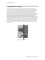
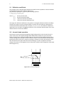
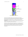
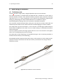
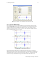
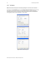
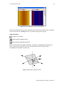
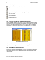
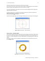
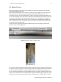
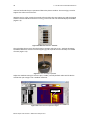
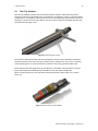
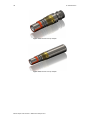
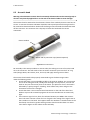
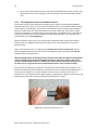
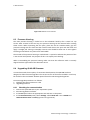
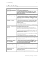
28 5 – Performance Check & Calibration 5 Performance Check & Calibration
5.1
Mirror rotation
Direction of motor rotation is clockwise viewed from top of tool (Figure 5‐1): Placing 2 fingers3 on the acoustic window may check mirror rotation. In time mode, record the 2 finger traces shown4 on the Abi surface browser. Remove your right finger from the acoustic window; the corresponding right finger trace on the Abi surface image should disappear. Figure 5-1 Direction of mirror rotation
5.2
Functionality test of the deviation system
5.2.1 Functionality test
The QL40 ABI‘s deviation system is factory calibrated and does not require further calibration. The functionality tests subsequently described have to be done to check that the tool is giving the correct deviation outputs: To verify inclination at 0° and 90°, position the probe vertical (acoustic head pointing down) for 0° inclination and horizontal for 90° inclination. Note that uphole measurement is possible with the APS544 deviation system as it includes 3 accelerometers. In uphole, the inclination will be between 90° and 180° (probe vertical, acoustic head pointing up). To verify azimuth accuracy, a good compass and an area free of magnetic materials must be used. Use a compass to orient North with the probe horizontal and verify that the azimuth reading is 0° ± 1°. Repeat the procedure for East, South and West directions. 5.2.2 Rolling test – azimuth and tilt check
Azimuth and tilt could be tested by rotating the tool about its long axis while maintaining both a constant inclination to the vertical, say 15°, and a fixed azimuth. The data imported into WellCAD should show a deviation of the azimuth less than the limit of ±2.5° and a deviation of the tilt less than the limit ±0.5°. 3
4
Wet your fingers first for a better coupling Adjust the amplitude scale to enhance the finger traces
Mount Sopris Instruments – www.mountsopris.com