1
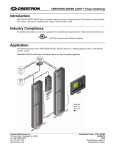
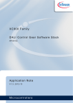
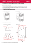
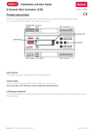
Installation and User Guide 458-UNI8 8-Channel Universal Dimmer Module Introduction The 458/UNI8 is an 8-channel universal, digital transistor, dimmer module. Each channel’s mode can be selected for either leading-edge or trailing-edge dimming. This provides compatibility with all common load types; inductive, capacitive and resistive. The unit incorporates a number of novel features that provide ‘first class’ performance when dimming modern LED lamps. This includes both mains dimmable retrofit lamps and LED drivers. Control inputs The 458-UNI8 can be controlled using DALI, S-DIM or DMX, and an override input. NOTE: DALI AND S-DIM / DMX MUST NOT BE CONNECTED SIMULTANEOUSLY. LCD display and keypad The front of the module has an LCD display and keypad to set basic configuration parameters and provide basic control of channel levels. Channels and load protection The 458/UNI8 module has 8 channels rated at 6 A, with a total current capacity of 48 A. Note: the correct chassis load protection must be chosen to ensure the required channel ratings are achieved, but not exceeded. Mains supply connector socket Attachment knob Heat sink Load cable sockets Connect cables from 458Mx chassis. Grille DALI connections Terminal block supplied with 458/UNI8. Override & S-DIM/DMX connections* Terminal block supplied with 458M1/M2/M3 chassis. LCD Display Attachment knob Keypad Contents Section Installation Mounting, environmental and clearance requirements Configuration Control panel LCD display and keypad Adjusting channel levels using the keypad Navigating the menu using the keypad Module Menu Options Status messages Technical Data Appendices Page 2 2 5 5 5 6 7 13 14 15 Appendix 1: 458/UNI8 Connections 15 Appendix 2: S-DIM/DMX wiring to next device & S-DIM/DMX termination 16 Doc. 7860303, issue 01 Installation INSTALLATION STEPS 1. Attach the module to a chassis 2. Connect power and load cables 3. Connect control wiring (DALI or S-DIM/DMX) 4. Connect Override input wiring (optional) 5. Replace chassis cover 6. Power on the 458-UNI8 7. Set S-DIM/DMX mode & base address (if using S-DIM/DMX control) 8. Configure the 458-UNI8 using Designer or Toolbox Mounting, environmental and clearance requirements Mounting • Attach the 458/UNI8 to a 458M1, 458M2, or 458M3 chassis, which is mounted vertically on a flat surface. Environment • • • • The ambient temperature must be between 0ºC and 40ºC. Air humidity must be between 0% and 90% (non-condensing). The area must be adequately ventilated. Do NOT install this product in a damp location. Clearance • For effective ventilation, ensure that there is adequate space around the combined chassis and module(s): 50 mm above, below and on both sides. • When a Helvar control module (e.g. dimmer unit) is attached, the grilles must NOT be obstructed. WARNING: BEFORE ATTACHING THE 458-UNI8 MODULE AND MAKING ANY CONNECTIONS, ENSURE THAT THE MAINS SUPPLY IS ISOLATED. IMPORTANT:The 458-UNI8 may be controlled by either DALI or S-DIM/DMX. However, DALI AND S-DIM / DMX MUST NOT BE CONNECTED AT THE SAME TIME. 1. Attach the module to a chassis 1.1. Remove chassis cover Refer to the 458Mx Chassis Installation Guide for details. In Step 5, you will replace the chassis cover. 1.2. Remove chassis blanking plates Unscrew and remove blanking plate(s) from the chassis. Blanking plate Note 1: 458M1: 1 blanking plate; 458M2: 2 blanking plates; 458M3: 3 blanking plates. Note 2: The diagrams on this page show the 458M1/8S06 chassis. Covers and knockouts are removed from the 458M2 & 458M3 in a similar way. 1.3. Loosen attachment knobs Partially unscrew the two knobs on the dimmer module to reveal the pins. 1.4. Slot module pins into mounting bracket Attach the module to the chassis by slotting the pins of the module to the mounting bracket. 1.5. Tighten attachment knobs Screw the knobs to the mounting bracket to secure the module. 2 Helvar 458/UNI8 8-Channel Universal Dimmer: Installation and User Guide Loosen knobs 2. Connect power and load cables See Appendix 1: 458/UNI8 Connections for diagrams. 2.1. Connect the power cable Connect the power cable from the 458Mx chassis to the 3-pin socket on the 458-UNI8 module. 2.2. Connect the load cables Disconnect the load cables from the bypass terminals in the 458Mx chassis. Connect the 8 load cables from 458Mx chassis to the eight 2-pin sockets on the 458-UNI8 module. Leave any unused load cables connected to the bypass terminals. 3. Connect control wiring: DALI or S-DIM/DMX Choose DALI or S-DIM/DMX. DO NOT CONNECT S-DIM/ DMX AND DALI SYSTEM AT THE SAME TIME. 3.a. 3.b. Connect the DALI cable If using DALI control, connect the DALI cable to the terminal block provided with the module. Make sure the terminal block is pushed firmly into the socket in the side of the module. Connect the S-DIM / DMX cable See Appendix 2: S-DIM/DMX wiring to next device & S-DIM/DMX termination for wiring diagrams. If connecting to S-DIM/DMX, plug in the connector of the S-DIM/DMX cable loom to the S-DIM/DMX terminals. This is attached to the DIN-rail inside the 458Mx chassis. Keep unscreened wire lengths to a minimum. 4. DADA+ DALI S-DIM/DMX termination If the dimmer is at either end of the S-DIM/DMX cable, wire a link between the ‘TERM’ and ‘B’ terminals of the S-DIM/DMX connector to enable cable termination. NC A [Data +] 0V [Data reference] SCN [Earth screen] B [Data -] TERM S-DIM/ DMX Link for termination Connect override input wiring (optional) Channel level override functionality Wire a switch between the ‘0V’ and ‘OVR’ terminals. Switch closure sets the light output of the channels to their override level, regardless of external control signals. For example, the override could be activated by contact closure on an alarm system. Override Vin < 1.5 V OVR 0V Ishort = 1 mA Set override levels using Designer software, or using the keypad and LCD display. Set override level for all channels, or set different override levels for each channel. 5. Replace chassis cover Replace the chassis cover using the original screws. The cover was removed in step 1.1. 3 6. Power on the 458/UNI8 Power up the dimmer unit by switching on the MCBs. The LCD display should appear as shown. 7. Set S-DIM or DMX mode and base adress (if using S-DIM or DMX control) Select S-DIM or DMX mode Use the control panel to select S-DIM or DMX mode, as shown below. The factory default setting is S-DIM mode. 8. Set S-DIM or DMX base address Use the 458/UNI8 keypad to set the S-DIM or DMX base address, as shown below. Configure the 458/UNI8 Designer software If the 458/UNI8 is connected to a router-based system (Helvar 905, 910 or 920 router, running Helvar’s Designer software, v. 4.2.18 or later), connect a PC to the router, and configure the 458/UNI8 using Designer software. Toolbox software You can configure the 458/UNI8 using a Windows PC (running Helvar’s Toolbox software, v. 2.3.3 or later) connected via USB or serial cable to the DALI network. Use a 510 USB interface, or other Helvar serial interface. Control panel You can use the control panel keys and display to adjust the DALI channel outputs directly, and configure options for all and individual channels. 4 Helvar 458/UNI8 8-Channel Universal Dimmer: Installation and User Guide Configuration We recommend configuring the 458/UNI8 using Designer software (4.2.18 or higher) or Toolbox software (2.3.3 or higher). You can also use the control panel keys and display to adjust the DALI channel outputs directly, and configure options for all and individual channels. Control panel LCD display and keypad LCD Display Main Screen: The Main Display Screen appears: - When the 458/UNI8 is powered on - After 60 seconds of inactivity on the Control Panel. - After exiting the control panel options Control panel keypad Use the keypad to: - Set dimmer channel levels - Navigate the system menus to adjust module settings ( ) S-DIM / DMX Activity and DALI Power / Activity Indicator For S-DIM / DMX the indicator is normally off, and flashes on intermittently for activity. If DALI power is on, then the indicator is on. It flashes to indicate DALI activity. Channel level %: The percentage shown is the level of DALI channel numbers the currently selected channel(s). ‘ALL’ is displayed here if all channels or outputs are selected simultaneously, but are set to different levels. Channel levels indicators 5 Adjusting channel levels using the keypad (From the LCD Display Main Screen): Press either RIGHT or LEFT to access the channel levels. Step left or right through channels. The selected channel(s) are shown by a flashing bar or ‘o’ (to indicate 0% light level). Adjust lighting level percentage (%) for the selected channel(s). Return to Main Display Screen Navigating the menu using the keypad 1. (From the LCD Display Main Screen): Press UP or DOWN to access the menu options. 2. Scroll through main options. 3. Select an option (access option screen). 4. Adjust parameters. 5. Step between different parameters in options screens. 6. Return to previous menu. Return to Main Display Screen (from main menu) 6 Helvar 458/UNI8 8-Channel Universal Dimmer: Installation and User Guide Module menu options Main Menu Use the keypad to access and navigate and adjust the menu options: see ‘Navigating the menu using the keypad.’ This table lists the main options available from the module control panel. Full options details are listed in the next section. Addresses Set S-DIM, DMX & DALI addresses, including base addresses, and S-DIM/DMX mode. Unit Details View module serial number, firmware version, and various other service-related information. Recall scene Recall DALI scenes. Save as scene Save levels as a DALI scene. Default scenes Reset DALI scenes to default settings. Groups Group and ungroup DALI channels. Dimming curves Select dimming curves for dimmer channels. Min fade time Set minimum fade times for DALI channels. Power on level Set DALI power-on levels for DALI channels. Failure level Set (or disable) DALI failure levels for DALI channels. Override level Set (or disable) override levels for DALI channels. Minimum level Set DALI minimum load levels for DALI channels. Switch-on level Set switch-on levels for S-DIM/DMX channels. Max load level Set maximum load levels for dimmer channels. Hysteresis Activate / De-activate S-DIM hysteresis for S-DIM channels. Dimming mode Set the dimming mode to match the characteristics of the load(s). Scaling high Set the upper limit (%) of the dimming control range to match the lamp characteristics. Scaling low Set the upper limit (%) of the dimming control range to match the lamp characteristics. LCD contrast Adjust the LCD contrast level. Factory reset Reset all settings to factory defaults. Use password Apply password lock to settings (except to ‘Unit details’ and ‘Enter password’ items). Enter password Remove the password lock (see ‘Use password’). The password is ‘58’. 7 Menu Options Details Addresses The digital interface (DALI or S-DIM/DMX) receives control messages from devices in the system. You can set any address to any channel. Note: The base address is the first channel address, from which the remaining addresses are allocated (unless changed manually in the address sub-menu). Sub-menu items Options S-DIM/DMX mode DMX or S-DIM (Default) S-DIM/DMX base S-DIM Base: DMX base: Disabled: S-DIM/DMX addr Channel: 1–8 S-DIM Address: 1 – 254; Disabled (Default: 1) DMX Address: 1 - 512; Disabled (Default: 1) Disabled: The address will not be re-allocated DALI base DALI Base: Disabled: 1 – 57 (Default: 1) The address will not be re-allocated DALI addresses Channel: Address: Removed: 1–8 1 – 64; Removed; Disabled Next time you connect it to a controller program or router, the DALI address will be re-allocated The address will not be re-allocated Disabled: 1 – 247 (Default: 1) 1 - 505 The address will not be re-allocated Unit Details Sub-menu items Options Details (Read-only) Serial number and Firmware version Mode Mode, power and data information If DALI power is on, a tick appears next to the DALI power field. DALI or S-DIM/DMX shows the last detected mode when the module was reset. User mode (All readonly); Refer to the ‘Troubleshooting’ section of this guide for message details. Recall Scene Recall a scene previously stored (temporarily if connected to a Helvar router system). Scenes are sets of lighting levels and can make use of any combination of channels. This option is always available, even when password protection is applied to other options. Range: Scene 1 -16 Save as Scene The levels which are currently active for all channels of the dimmer are applied to this scene. You can recall stored scenes in the ‘Recall Scene’ menu (see above). Range: Scene 1 -16 Default scenes Default lighting scenes can be applied to the dimmer channels, i.e. scene 1 = 100%, scene 2 = 75%, scene 3 = 50%, and scene 4 = 25%. Note:Lighting levels are NOT changed automatically once you apply default scenes; but once you recall a scene, lighting is set to the levels for that scene. 8 Helvar 458/UNI8 8-Channel Universal Dimmer: Installation and User Guide Groups Assign channels to DALI groups. Any channel can be assigned to any group. Options: Group: 1 – 16 Selected: (Up button); Not selected: x (Down button). Dimming curves Configure the shape of the dimming curve to suit the requirements of your lighting equipment. Options: Channel: 1 – 8; ALL Curves: 0: Non-dim (‘Switch mode’) 1: LED 2: Linear 3: LED Min fade time Set the minimum time it takes to change between minimum and maximum lighting levels. Options: Channel: 1 – 8, ALL Fade time: 0: 20 ms 1: 150 ms 2: 500 ms 3: 1 sec (Default) Power on level Set the level each channel will go to when the unit is powered on, with DALI connected. Note: Power-on levels for S-DIM are set in the router, and not using the control panel. In S-DIM mode, Power on level is fixed at 0% and controlled by the router. Options: Channel: 1 – 8; ALL Power on level: 0 – 100%; Last (Default in DALI mode:100%) Failure level Set channel levels for situations where the DALI bus goes low, such as when it is short-circuited or the DALI PSU is turned off. Options: Channel: 1 – 8; ALL Failure level: 0 – 100%; **** (= do not apply Failure level); 8 (Ignore) (Default:100%) 9 Override level If the override input connection is short-circuited, e.g. by contact closure on an alarm system, all channels are set to their override level, regardless of external control signals. Options: Channel: 1 – 8; ALL Override level: 0 – 100%; **** (= do not apply override level); (Default:100%) Minimum level[Displayed only when the module is in DALI mode: see Addresses menu] Set the minimum DALI lighting level the channel will achieve when turned on, no matter what scene is called or level is set. For example, if you set a minimum level of 50% and call scene 4 (at 25% level), the channel output level will be 50%. For S-DIM/DMX, the level set here is actually the switch-on level, and the channel will not turn on unless it receives a command to go to or above this level. See Switch-on level (below). The minimum level is 1% by default. If you set the minimum level to 100%, this forces the dimming curve into switch mode. Options: Channel: 1 – 8; ALL Minimum level: 0.1%; 1% – 100%; (Default: 0.1%) Switch-on level [Displayed only when the module is in S-DIM/DMX mode: see Addresses menu] Set the switch-on levels for S-DIM/DMX channels. Options: Channel: Switch-on level: 1 – 8; ALL (Default) 0% – 64%; (Default: 2%) Max load level Limit the maximum output level of each channel. You can set the maximum level to between 1% and 100%. Note: The maximum level is 100% by default. Options: Channel: 1 – 8; ALL Maximum level: 1% – 100%; (Default:100%) 10 Helvar 458/UNI8 8-Channel Universal Dimmer: Installation and User Guide Hysteresis Note: Hysteresis is supported only when controlled by S-DIM. This setting affects the level at which the channel turns off. When hysteresis is on, the switch-off level is 80% of the switch-on level. At or below the switch-off level, the channel will be off. For example, if the switch on level is 50%, and the signal rises to this level or above, the channel turns on, then if the signal falls to 40% or below, the channel turns off. By default on the dimmer: - When hysteresis is on and the signal rises to 2%, the lighting for that channel turns on; when it falls to 0%, the channel turns off. - When hysteresis is off (default setting) and the signal rises to 2%, the lighting for that channel turns on; when it falls to 1%, the channel turns off. Options: Channel: 1 – 8; ALL Off: (up button); x (down button) (Default: x) Dimming mode Set the dimming mode to match the characteristics of the load(s). Options: Channel: 1 – 8; ALL Mode Modes: 0: Non-dim: 1: Trailing: 2: Leading: 3: Inductive: Typical load Loads which do not dim (e.g. fixed output LED drives and small fans. Incandescent & mains halogen lamps; trailing edge electronic transformers and LED lamps. Leading edge LED lamps Wire-wound transformers and inductive loads Scaling high and Scaling low Set these values to scale the dimming curves. This provides optimum performance for lamps that have restricted dimming characteristics. Options: Channel: 1 – 8; ALL Range: 0% – 100%; (Default: Mininum 0%; Maximum 100%) LCD Contrast Set the LCD display contrast: 0–100% (default: 40%) Note 1: Even at 0%, the text is just visible. Note 2: The display adjusts as you raise or lower the contrast value, but you must press ‘OK’ to select that contrast level. Factory reset Reset the module to the original settings (defaults). Note: Restoring factory settings returns all connected lighting to default levels immediately. Press and hold ‘OK’ for 10 seconds until , a ‘ Done’ message appears. 11 Use password Note: The password is disabled by default. You can use the factory-set password for the module. If the password is enabled, you must enter the correct password, otherwise you can only use the following functions / menus: • Change dimmer levels • View technical information about the module • Recall a scene • Enter the password If you chose to use the password, after 1 minute of inactivity, the Control Panel goes to standby and the ‘Enter password’ menu appears in ‘Main Menu’. ‘Use password’ disables the functionality of the remaining menus. You can access the menus but cannot change any settings, unless you enter the password (58). A key ( ) is displayed in the bottom right of the screen when you enter the menu, to indicate that you cannot enter any settings. Options: Use password: (password is 58) (up button); x (down button) (Default: x = no) Press ‘OK’ to confirm new selection, and a “ Done” message appears. The password lock will be applied after a period of 60 seconds from this message appearing. Enter password If the password is enabled and you wish to use all of the functions of the module, you must enter the correct password. 12 Helvar 458/UNI8 8-Channel Universal Dimmer: Installation and User Guide Status messages Status messages are displayed on the bottom row of the LCD display. Message Reason and recommended action Dimmer too Hot! Dimmer heatsink getting too hot - Reduces the dimmer is reducing its output levels. Reduce the load or check peak load currents. Preceeds temperature trip; > 80oC. Load too heavy! Output current too high - the dimmer is reducing its output levels. Reduce the load. Off - Frequency is < 45Hz or > 65Hz Mains V too low Mains voltage too low. Off - > 276 volts RMS Off - < 70 volts RMS Mains V too high Mains voltage too high. Output Trip Notes Mains frequency Mains frequency outside limits Off - Frequency is < 45Hz or > 65Hz Current zero Internal error. Cycle power. - - - Starting up... Channel is starting up (Displayed only briefly). - - - Current measure Internal error. Cycle power. - - - 12V supply bad Channel power fault. - - - No zero crossing No zero crossings observed (informative after Mains Freq trip) Off - Mains zero crossings not detected for 2.5 seconds Temp sensor fail Temperature sensor failure Off Latched; resettable Off Latched; resettable Off Latched; resettable Temp update trip Temperature update failure. Check Off Latched; resettable Fast overcurrent Output severely overloaded or Off Latched; resettable Off Latched; resettable Avalanche V trip Output over-voltage, check that Off Latched; resettable RMS load V trip Output over-voltage, check load compatibility. Off Latched; resettable Halfwaving off Output current not symmetrical; dimmer has switched off. Off Latched; resettable Halfwaving on As above but dimmer has latched to full to protect the load. Off Latched; resettable Temperature trip Temperature became too high. Reduce the load or check peak load currents. Temp rate trip Temperature rising too fast. Severely overloaded. control power and reset channels. short-circuited. RMS overcurrent Output overloaded. Reduce the load. inductive loads are using the “inductive” dimming mode. 13 Technical Data Connections Conformity and Standards Mains supply: Solid core: up to 4 mm² Stranded: 2.5 mm² EMC Emission: EN 55015 DALI: Wire size: 0.5 — 2.5 mm² Recommended: 1.0 — 1.5 mm² Max. length: 300 m @ 1.5 mm² EMC Immunity: EN 61547 Safety: EN 60950-1 Environment: Complies with WEEE and RoHS directives DALI data transfer: According to DALI standard IEC60929, with Helvar extensions S-DIM/DMX: 0.22 - 1.5 mm² low loss RS485 type (multi-stranded, twisted and shielded) Override (OVR): 0.5 — 1.5 mm² (screened and twisted) Cable rating: All cables must be mains rated Power supply Mains supply voltage: 85-264 VAC, 45-65 Hz Power consumption: 1.3 W External MCB protection: Max. 6 A (control circuit). The external power supply must be protected. Isolation: 4 kV between mains supply; DALI; and S-DIM/DMX/Override connectors. Standby power: 2W Max. total losses: TBD DALI consumption: 2 mA S-DIM data transfer: Helvar protocol (RS485, 115 kpbs) DMX data transfer: Configuration software Configure using Designer version 4.2.18 (or higher), or Toolbox version 2.3.3. (or higher) Mechanical Data Material: Housing: Powder coated steel (black) Heatsink: Anodised aluminium IP rating: IP 20 (For installation in a restricted access location only) Mounting: Attached to 458M1, 458M2, or 458M3 chassis Weight: 3.9 kg Module dimensions: 360 x 105 x 170 mm Supply Supply current: 48 A (max) Maximum load: 8x6A Output regulation: Automatic compensation for supply voltage and frequency variations 170 Protection For load protection, refer to 458Mx installation guide. Active bottom load: PTC protection: resettable fuse 360 Thermal protection: Control board – resettable fuse, power devices – thermal sensing Inputs Control: DALI; S-DIM or DMX Override (OVR): Wired override input User interface: Control panel: 5 push buttons and LCD screen for configuration Operating Conditions 105 Ambient Temperature: 0°C to +40°C Relative Humidity: Max 90%, non-condensing Storage Temperature: -10°C to +70°C DMX512-A protocol 14 Helvar 458/UNI8 8-Channel Universal Dimmer: Installation and User Guide Appendices Appendix 1: 458/UNI8 Connections The diagram shows the 458M1 chassis. Cable connection is similar for the 458M2 and 458M3. Power cable Power cable from 458Mx chassis : connects to the 3-pin socket on the 458-UNI8 module. Load cables 8 load cables from 458Mx chassis: connect to the eight 2-pin sockets on the 458-UNI8 module. Control wiring Choose DALI or S-DIM/DMX. DO NOT CONNECT S-DIM/DMX AND DALI SYSTEM AT THE SAME TIME. Power cable from 458Mx chassis 1 2 3 4 5 6 7 8 Load cables from 458Mx chassis DALI Override & S-DIM/DMX DADA+ Override S-DIM/ DMX Bypass terminals S-DIM/DMX cable loom OVR: Vin < 1.5 V; Ishort = 1 mA 0V NC A [Data +] 0V [Data reference] SCN [Earth screen] B [Data -] TERM Link for termination 15 Appendix 2: S-DIM/DMX wiring to next device & S-DIM/DMX termination S-DIM/DMX wiring to next device S-DIM/DMX termination 458M2 & 1x 458 module 458M2 & 1x 458 module A[+] 0V SC B[-] TERM A[+] 0V SC B[-] TERM B[-] SC 0V A[+] B[-] SC 0V A[+] Termination link: TERM to B 458M2 & 2x 458 modules 458M2 & 2x 458 modules A[+] 0V SC B[-] TERM A[+] 0V SC B[-] TERM Termination link: TERM to B A[+] 0V SC B[-] TERM B[-] SC 0V A[+] A[+] 0V SC B[-] TERM 458M3 & 3x 458 modules 458M3 & 3x 458 modules A[+] 0V SC B[-] TERM A[+] 0V SC B[-] TERM B[-] SC 0V A[+] Termination link: TERM to B A[+] 0V SC B[-] TERM A[+] 0V SC B[-] TERM A[+] 0V SC B[-] TERM A[+] 0V SC B[-] TERM Doc. 7860303, issue 01. 14.04.2014 B[-] SC 0V A[+] B[-] SC 0V A[+] 16