1
2.5
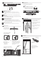
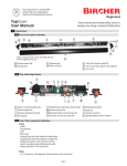
Selecting the switching and operating modes
2.7
Mounting the sensor
Mount the sensor in the housing and slide
both mounting brackets against the sensor.
Switch 1
1 2
1 2
1 2
Note:
Put cable behind the mounting bracket.
Make sure the red screws on the mounting brackets are fully unscrewed before
inserting the sensor into the brackets.
Switch 2
1 2
Operating mode: moving or stationary
Moving mode: Switch 1 up
1 2
1 2
1 2
– no background necessary, floor is ignored (background suppression)
– the sensor cannot be tested in this operating mode (test input TI without
function)
1 2
Stationary mode: Switch 1 down (not recommended if mounted on a
moving door)
1 2
1 2
– a stable background is essential, the floor is analyzed (background evaluation)
– the sensor can be tested via the test input
1 2
1 2
2.6
Switching mode active/passive variable
Passive variable: Switch 2 up
1 2
– on detection, the relay switches from common to nc (see section 2.6)
– this setting has the advantage that a power failure or wire damage is interpreted as a detection and will trigger the respective safety feature of the door
2.8
Checking the settings
Power on the sensor after all installations have been completed
Active switching: Switch 2 down
– on detection, the relay switches from common to no (see section 2.6)
Check the detection range with a regular sheet of paper (white, letter size) or
the palm of your hand.
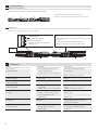
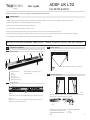
Electrical connection
If necessary, adjust the detection characteristics as described in sections 2.9,
2.10 and 2.11.
The terminal block can be
pushed
– ⁄ ~ out from below with
1
+⁄~
a screwdriver
if necessary2
commun
nc
no
TE*
–⁄~
+⁄ ~
commun
nc
no
TE*
3
4
5
6
Note: The LED lights up when the
sensor detects a presence.
1
2
3
4
5
6
Connect the cables to the terminal
based on the diagram below
standard
–⁄~
+⁄~
common
no
nc
TI*
switch 2 down
1
2
3
4
5
6
white
brown
green
grey
yellow
*Test input (only if switch 1 is down)
Note on test input:
Testing is only possible for:
–⁄~
1
– stationary
mode
+⁄~
2
– DCcommon
supply Power
3
nc
no
TE*
4
5
6
–⁄~
+⁄~
common
nc
no
TI*
1
2
3
4
5
6
white
brown
green
grey
yellow
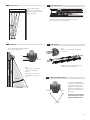
2.9
Scanning range
Function of test input:
When the test input is active (voltage
present), the sensor is switched off.
This simulates a detection and when
–⁄~
1
functioning
correctly causes
the
+⁄ ~
2
relay
to switch.
3
common
nc
no
TE*
Decreasing the
scanning range
4
5
6
Set the scanning range to
approx. 9.84” (25 cm) above the
floor with a maximum of 28” to
fulfill ANSI 156.10.
Plug the plug-in screw terminal back in
again and route the cable away over the
guide bridge.
Decreasing the
scanning range
Increasing the
scanning range
2
Increasing the
scanning range
Adjust the scanning range with
the adjustment wheel.