1
2.10
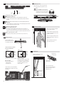
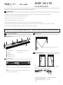
Adjust detection area
2.12 Secure the sensor position
Adjust the detection area by
sliding the sensor (red mounting
brackets should be partly unscrewed
for easy adjustments).
When all the settings are completed, secure the sensor by tightening the red screws on the mounting brackets.
2.11
Inclination angle
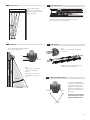
2.13 Closing the housing
Note:
If necessary, cut out the cable exit indicated on
the end cover.
Set the inclination angle by carefully rotating the
sensor up or down with 2 hands.
30°
Scale
0°
0 to 30°
Attach the front cover to the aluminium housing.
Mount the end caps using the screws.
2m
6.56’
(2 m)
2 m (6.56')
Note:
The angle of 0° to 30° can be read
on the sides of the mounting
brackets.
Make sure to set the same angle
on both brackets to have a level
sensor.
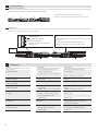
2.14 Adaptation for ANSI/BHMA compliance
0 à 30°
To comply with the ANSI/BHMA
requirement of 1” max between leading edge and sensing field, cut the
side braket on the leading edge side
1.15 m
and slide the sensor/brackets assembly as far as possible towards the
leading edge.
1.15 m(1.15m)
(3.77')
3.77’
The Topscan has been independently tested by TÜV and certified
compliant with ANSI standards.
side brackets
3