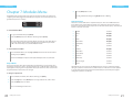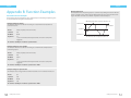
1
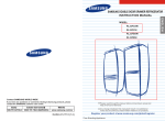
Copyright © 2010-2011 Dynon Instruments DBA Digital Aquatics. All rights reserving, no part of this manual may be reproduced, copied, transmitted, disseminated or stored in any storage medium, for any purpose without the express written permission of Digital Aquatics. Digital Aquatics hereby grants permission to download a single copy of this manual and of any revision to this manual onto a hard drive or other electronic storage medium to be viewed for personal use, provided that such electronic or printed copy of this manual or revision must contain the complete text of this copyright notice and provided further that any unauthorized commercial distribution of this manual or any revision hereto is strictly prohibited. Information in this document is subject to change without notice. Digital Aquatics reserves the right to change or improve its products and to make changes in the content without obligation to notify any person or organization of such changes. Visit the Digital Aquatics website (www. DigitalAquatics.com) for current updates and supplemental information concerning the use and operation of this and other Digital Aquatics products. ReefKeeper Lite User Guide Firmware 2.01 Contents Contents Contents Chapter 6 14 = Preface iii About This Guide Part 1 Getting Started Chapter 1 Chapter 2 Chapter 3 1 Product Overview 1 What Is Included 2 Head unit 2 iTemp Temperature Probe System Menu 14 Brightness 15 Sound 15 Date/Time 16 Lock Keys 17 Units 18 Communication 18 Info 19 Factory Reset Chapter 7 20 Modules Menu 20 Output Modes 21 Output Functions 40 Output Alarms 41 Input Calibration Chapter 8 42 Timers Menu Chapter 9 44 Alarms Menu 3 Installation 3 Wiring Your System 4 General Mounting 4 Mounting The RKL Head unit 5 Mounting The PC4 5 Mounting The SL1 5 Mounting The NET Part 3 5 Bus Cable Routing Support 6 General Interface 6 Getting Around Appendix A 48 Glossary Home Screen Appendix B 50 Function Examples 6 Part 2 Programming Chapter 4 9 Chapter 5 10 i ReefKeeper Lite User Guide Main Menu General Menu 10 Standby 11 Night Mode 12 Wave Maker 13 Storm Mode ReefKeeper Lite User Guide ii About This Guide Getting Started About This Guide Part 1 Icon Definitions Getting Started A exclamation point within an equilateral triangle is intended to alert the user of a cautionary notice to which attention should be given prior to the products usage. A lowercase “i” within a circle is intended to alert the user to the presence of important operating information in the literature accompanying the product. This symbol is also used for Notes. A jagged arrow within an equilateral triangle is intended to alert the user of a hazardous warning that involves the possibility of electrical shock. Disclaimers • • • As with most electronic devices, contact with water will cause unrepairable damage and is not covered under any warranty. The ReefKeeper Lite carries a limited 1 year warranty against manufacturer defect. All probes sold by Digital Aquatics have a limited 90 day warranty unless otherwise stated. Some probes may be covered by the manufacture and not Digital Aquatics. Commonly Used Abbreviations iii RKL ReefKeeper Lite System MLC Moon Light Controller GC2 ReefKeeper Lite Head unit ALC Advanced Light Controller Network Interface Device SID System Interface Device NET PC4 Power Controller 4 SW5 Switch 5 PC1 Power Controller 1 RD1 SL1 System Lab 1 APC Advanced Pump Controller SL2 System Lab 2 AP1 ReefKeeper Lite User Guide Remote Display 1 Advanced Probe 1 Chapter 1: Product Overview What Is Included Depending on what ReefKeeper Lite (RKL) system package was purchased, the kit will have the following hardware. RKL BASIC RKL PLUS RKL NET 1 x RKL Head unit 1 x PC4 Module 1 x SID * 1 x iTemp Probe 1 x Programming Coupler 4 x Mounting Screws 1 x RKL Head unit 2 x PC4 Module 1 x SL1 Module 1 x SID * 1 x iTemp Probe 1 x pH Probe 1 x 3Ft Bus Cable 1 x 6Ft Bus Cable 1 x Programming Coupler 8 x Mounting Screws 1 x RKL Head unit 2 x PC4 Module 1 x SL1 Module 1 x NET Module 1 x SID * 1 x iTemp Probe 1 x pH Probe 1 x 1Ft Bus Cable 1 x 3Ft Bus Cable 1 x 6Ft Bus Cable 1 x 7Ft Network Cable 1 x Programming Coupler 10 x Mounting Screws * The SID is the device used to update the RKL and any modules via a USB port on a Windows computer The SID is also used for communication with the myReef Application. At the time of this printing, the Programming Application is only compatible with the Windows operating system. It is not compatible with the Apple OS or Linux OS. ReefKeeper Lite User Guide 1 Getting Started Getting Started Head unit The RKL head unit is the main control unit for the entire system. All settings and configurations are set and stored within it. Chapter 2: Installation Wiring Your System 2 1 ReefKeeper Lite LCD Screen 2 Module Indicator LEDs 3 Dual usage Enter / Status key 4 Dual usage Back / Standby key 1 3 The ReefKeeper Lite (RKL) is a modular system. All modules are connected together via the bus cables included with the system. There is not a specific order when connecting modules to the system, nor is there a required port order. Below are connection examples for each one of the RKL system packages. These examples are intended to show a possible connection scheme for your system. 4 ReefKeeper Lite Head unit iTemp Temperature Probe Ma x Cur ren t Per Cha 2 1 2 nne The ReefKeeper Lite System has the unique ability to monitor temperature from a probe connected directly to the system bus. The probe consists of a standard temperature probe with an RJ bus connection on one end. This allows the probe to be connected at the end of the bus chain and lets the RKL system monitor temperature without the usage of an SL1. Besides the physical connection of the iTemp probe, iTemp is treated exactly the same as any other input on the system. l 4 3 Bus 1 ReefKeeper Lite BASIC: Connection Example p H Te m p itch Sw s tu a St O RP Bu s Ma x Cur ren 1 2 t Per Cha 2 nne l 4 3 iTemp Temperature Probe Bus 1 Ma x Cur ren 1 2 t Per Cha 2 nne l 4 3 Bus 1 ReefKeeper Lite PLUS: Connection Example 2 ReefKeeper Lite User Guide ReefKeeper Lite User Guide 3 Getting Started Getting Started Mounting the PC4 s atu St Bu s Mount the PC4 in a well ventilated location. Also, make sure it can be accessed in the event maintenance must be done, such as a firmware upgrade. p H Te m p itch Sw St a tu s RP O Bu s PC4s should never be mounted on the floor or any other surface where water can pool. Ma x Cur ren 1 2 t Per Cha 2 nne l 4 3 Bus 1 Ma x Cur ren 1 2 t Per Cha 2 nne l 4 3 Bus 1 Mounting the SL1 (Included with the RKL PLUS and RKL NET package) Mount the SL1 in a well ventilated location; close enough to the tank or sump so that all probe wires can reach their mounting locations. Also, make sure it can be accessed in the event maintenance must be done, such as a firmware upgrade. ReefKeeper Lite NET: Connection Example There is no required order when connecting a ReefKeeper Lite system. General Mounting It is important that electronic equipment never be mounted on the ground or the bottom of a cabinet. All Digital Aquatics modules should be mounted as high as conditions will allow. Also, all bus cables, probe wires, and power cords should use proper drip loops. Correct Installation w/ Drip Loop Mounting the NET (Included with the RKL NET package) Mount the NET in a well ventilated location. Please be aware that the module must be within wiring distance of a network connection. Also, make sure it can be accessed in the event maintenance must be done, such as a firmware upgrade. Bus Cable Routing It is important to make sure bus cables are routed in a way that will keep them safe. Make sure they cannot get pinched or crimped. Damaging a bus cable can cause system wide failure. It is also important to keep bus cables clear of lighting ballasts and wiring. Bus cables can pick up electronic noise and in extreme cases this noise can cause interference to the system. Incorrect Installation w/o Drop Loop Water damage is not covered by product warranties and is the leading cause of device failure. It is the responsibility of the user to insure safe installation practices are followed. Mounting the RKL Head unit Mount the head unit in a location where it can be easily accessed for daily operation. While the face of the head unit is splash resistant, proper ventilation is important. 4 ReefKeeper Lite User Guide ReefKeeper Lite User Guide 5 Getting Started Getting Started Chapter 3: General Interface Getting Around The ReefKeeper system and head unit have been designed to be as intuitive and easy to use as possible. Navigation through the head unit can be accomplished by using the [UP] and [DOWN] arrow keys. The [UP] key is indicated by a triangle pointing upward and the [DOWN] key is indicated by a triangle pointing downward. Menus can be entered and exited using the [ENTER] Standby Standby is a timer that can be set to turn ON or OFF outputs for a user programmable duration of time. Typically, Standby is used to temporarily turn off pumps for maintenance or feeding. Once the Standby timer has finished counting down, all outputs set to use Standby will automatically resume their normal operation. Each device can individually be set to use standby. and [BACK] keys receptively. Example screen after Standby has been started Home Screen The home screen gives you quick and easy access to the most important information in your system. Standby can only be started from the Home Screen. It will appear on the lower line when active. Standby has a factory default setting of 30 minutes. To set up Standby Example Home Screen Date and Time The Date and Time are displayed in the top half of the display. The date is formatted as the current day of week followed the current day of the month. The time is formatted based on a 12 hour clock using the A (AM) and P (PM) designators. Please see page 12 on how to change the current date and time. To set an Output to use Standby 1 When on the Home Screen, Press the [Back] / Standby button. The lower line will say “Standby”. 2 Press the [Enter] button to start Standby. The time will appear next to “Standby”, it will begin to countdown, signaling that Standby is now active. Once the standby time has expired, the system will go back to normal operation and the channels will function based on their programming. A port that has been removed from the system will show up as “error” The quick data will always say “None” when powered up as it does not store the sensor that it was previously set to. Please see the output function setup instructions in Chapter 7. To start Standby Quick Data Quick Data can display any port (input/output) attached to the system. This allows for quick access to all of your systems parameters without having to navigate through the menus. Please see the General menu instructions in Chapter 5. To cancel Standby Press the [Back] button. To change quick data 6 Press the [Up] button to go up through the port list. Press the [Down] button to go down through the port list. ReefKeeper Lite User Guide Standby can be stopped early once activated. Standby and its timer will be removed from the screen. The previous quick data will take its place. ReefKeeper Lite User Guide 7 Getting Started Programming Alarm Notification Part 2 When an alarm is set to use a the flash or beep notification, it will appear on the home screen. The alarm will appear on the top line as “AlarmXX”, where the XX is the number of the active alarm. Programming Example Alarm Notification Chapter 4: Main Menu To stop an alarm’s flashing or beeping Pressing [Menu] enters the menu system. The menu system is structured as follows. When on the Home Screen, Press the [Back] button. To remove the alarm message from the screen When on the Home Screen, Press the [Enter] button. The alarm condition must be cleared before the alarm message will be removed from the screen. For example, if a temperature alarm of 80 degrees triggers an alarm, the “Alarm” message on the screen will stop displaying if and only if you press [Enter] and the temperature is currently below 80 degrees. 8 ReefKeeper Lite User Guide General System Modules Timers Alarms Pressing the arrow keys will navigate through the menu options listed above. Once the desired item is flashing, press [Enter] to make your selection. ReefKeeper Lite User Guide 9 Programming Programming Chapter 5: General Menu You can go back from a save by pressing [Back] when save is flashing. The General menu includes the following settings. Standby Night Mode Wave Maker Storm Mode To navigate to the General menu 1 On your ReefKeeper Lite head unit, hit the [Menu] key. 2 Press [Down] until “General” is flashing and press [Enter]. Night Mode The Night Mode option sets a night time period for your system. This feature can be used for the following items: The MLC/ALC modules (sold separately) can use the Lunar function to turn on lights during Night Mode. The Pump function have options to turn pumps ON or OFF during Night Mode. The LCD screen has a brightness option for both Day Mode and Night Mode. To set Night Mode 1 The first setting is the Night Mode Start Time. Hours will be flashing. Standby The Standby option is a timer that can be triggered from the Home Screen. Outputs can use this timer to turn ON or OFF for various reasons such as feeding or maintenance. Only the minutes and seconds can be set in the Standby timer with a maximum duration of 59 minutes and 59 seconds. From the General Menu, press [Down] until “Night Mode” is flashing and press [Enter]. 2 Press the [Up] or [Down] buttons to change the current values for Hours, Minutes and Seconds. Move from one field to the next by hitting [Enter]. 3 After the last field for Night Start is set, press the [Enter] button to confirm. To set Standby The next setting is the Night Mode End Time. Hours will be flashing. 1 From the General Menu with Standby flashing, press [Enter]. 4 Press the [Up] or [Down] buttons to change the current values for Hours, Minutes and Seconds. Move from one field to the other by hitting [Enter]. 5 After the last field for Night Start is set, press the [Enter] button to confirm. The middle time option (Minutes) will be flashing and ranges from 00 to 59. 2 Press the [Up] and [Down] buttons to change the minutes to the desired value and press the [Enter] button to confirm. The last time option (seconds) will then start flashing and ranges from 00 to 59. 3 Press the [Up] button or the [Down] button to change the seconds to a desired value and press the [Enter] button to confirm. The screen will change and show “Save”. 6 Press the [Enter] button to save. You can go back from a save by pressing [Back] when save is flashing. The screen will change and show “Save”. 4 10 Press the [Enter] button to save. ReefKeeper Lite User Guide ReefKeeper Lite User Guide 11 Programming Programming Wave Maker Storm Mode The wavemaker setting allows the user to configure two opposing pump cycles, A and B. These settings can be used with the Wave Maker function to generate turbulent flow within your tank. Since these cycles oppose each other, WM A is always ON when WM B is OFF and vice versa. The “Storm Mode” setting is used to create random ON and OFF durations of the devices on the system. For example, if a light is programmed to use storm mode, it will turn ON and OFF at random time intervals. Storm Mode can be used on Lights and Pumps. To set Wave Makers To set up Storm mode 1 From the General Menu, press [Down] until “Wave Maker” is flashing and press [Enter]. 1 The first option will be “Day Of Week” and the first “-” will be flashing by default. “Day Of Week” represents the days of the week that you would like Storm Mode to operate and is displayed as a sequence of dashes. Any or all of the days can be selected for Storm Mode. The first setting is the amount of time that Wave Maker A will be ON, shown by “WM A”. Hours will be flashing. 2 Press the [Up] or [Down] buttons to change the current values for Hours, Minutes and Seconds. Move from one field to the other by hitting [Enter]. Hours range from 0 to 11. Minutes and seconds range from 00 to 59. 3 Example: “S - - W - - S” = Sunday, Wednesday, Saturday “Active 2 After the last field is set, press the [Enter] button to confirm. The next setting is the amount of time Wave Maker B will be ON, shown by “WM B”. Hours will be flashing. 4 Press the [Up] or [Down] buttons to change the current values for Hours, Minutes and Seconds. Move from one field to the other by hitting [Enter]. 5 After the last field is set, press the [Enter] button to confirm. 3 Press the [Up] or [Down] button to set the first field (hour), press [Enter] to set and move to the next field. The next prompt will be for the “On Duration” time with the first field (hour) flashing. This is not a standard time but a total duration that Storm Mode is to be in the ON state. 4 Press the [Up] or the [Down] buttons to change between “Yes” and “No” and press enter to confirm. Press the [Up] or [Down] buttons to select the first day, press [Enter] to set and move to the next day. Continue until all days are set and press [Enter] to confirm. The next prompt will be for the “Start” time with the first field (hour) flashing. The next prompt is for “Random”. Selecting “Yes” will vary the On and Off durations between zero and the maximum set. The On and Off durations set in the earlier steps determine the maximum value. 6 From the General Menu, press [Down] until “Storm Mode” is flashing and press [Enter]. Press the [Up] or [Down] button to set the first field (hour), press [Enter] to set and move to the next field. The next prompt will be for the “Off Duration” time with the first field (hour) flashing. This is not a standard time but a total duration that Storm Mode is to be in the OFF state. 5 Press the [Up] or [Down] button to set the first field (hour), press [Enter] to set and move to the next field. The screen will change and show “Save”. 7 The next prompt is for “Repeat Count” and specifies the number of on/off cycles that the Storm Mode will repeat. The default state is “00” and indicates that Storm Mode will not repeat. When set to 01 Storm Mode will repeat one time. Press the [Enter] button to save. You can go back from a save by pressing [Back] when save is flashing. 6 Press the [Up] or [Down] button to set the field, press [Enter] to set. The screen will change and show “Save”. 7 Press the [Enter] button to save. You can go back from a save by pressing [Back] when save is flashing. 12 ReefKeeper Lite User Guide ReefKeeper Lite User Guide 13 Programming Programming Chapter 6: System Menu The screen will change and show “Save”. The System menu includes the following settings. 4 Press the [Enter] button to save. Brightness Sound Date / Time Lock Keys Sound Units The Sound setting is used to turn on or off the tone associated with a button press. Changing the Sound setting to “OFF” does not affect audible alarms. Communication Info Factory Reset To navigate to the System menu 1 On your ReefKeeper Lite head unit, hit the [Menu] key. 2 Press [Down] until “System” is flashing and press [Enter]. You can go back from a save by pressing [Back] when save is flashing. To set the Sound option 1 From the System Menu, press [Down] until “Sound” is flashing and press [Enter]. 2 Press the [Up] or [Down] buttons to change between “On” and “Off” and press the [Enter] button to confirm. The screen will change and show “Save”. 3 Press the [Enter] button to save. You can go back from a save by pressing [Back] when save is flashing. Brightness The Brightness setting determines how bright the LCD screen is for viewing. The LCD can have different brightness levels for Day Mode and for Night Mode. The level will automatically change when the system transitions from day to night and back again. Date/Time To set the Brightness level of the screen Date is used to keep track of the day of the week as well as the current lunar cycle for the Lunar function. Time is used to trigger lights on and off as well as timers. 1 From the System Menu, press [Down] until “Brightness” is flashing and press [Enter]. Time does not automatically update with daylight savings time. The first setting is for the level of brightness during Day Mode. To set the Date and Time 2 Press the [Up] or [Down] buttons to set the desired level and press the [Enter] button to confirm and advance to the next value. 1 The next setting is for the level of brightness during Night Mode. 3 14 Press the [Up] button or the [Down] button to set the desired level and press the [Enter] button to confirm. ReefKeeper Lite User Guide From the System Menu, press [Down] until “Date/Time” is flashing and press [Enter]. The first option is to set the system’s date. The Year will be flashing and ranges from 2000 to 2099. 2 Press the [Up] button or the [Down] button to change the year to the desired value and press the [Enter] button to confirm and advance to the next value. ReefKeeper Lite User Guide 15 Programming Programming The next option is to set the system’s month and ranges from Jan to Dec. 3 Press the [Up] button or the [Down] button to change the current month to a desired value and press [Enter] to confirm and advance to the next value. 1 From the System Menu, press [Down] until “Lock Keys” is flashing and press [Enter]. 2 Press the [Up] or [Down] buttons to change between “Yes” and “No”. 3 Press the [Enter] button to confirm. If “Yes” is selected the system will display the Home Screen with “Locked!” on the bottom line. The “Locked” will disappear and display the Quick Data. At any time if a key is pressed and the display is locked the “Locked” will appear for four seconds. To navigate the system again, use the unlock button code. The next option is to set the system’s day and ranges from 1 to the current month’s maximum. 4 Press the [Up] button or the [Down] button to change the current day to a desired value and press [Enter] to confirm and advance to the next value. The next option is to set the system’s time. The hour will be flashing and ranges from “1” to “12”. To unlock the keys 5 Press the [Up] button or the [Down] button to change the hour to the desired value and press the [Enter] button to confirm and advance to the next value. The next option is to set the minutes and ranges from “1” to “59”. 6 Press the [Up] button or the [Down] button to change the current minutes to a desired value and press [Enter] to confirm and advance to the next value. From the Home screen, press [Up], [Down], [Up], [Enter]. Your keys should now be unlocked. Units The “Units” setting affects the display of temperature on the system. Temperature can be displayed as either Fahrenheit (F) or Celsius (C). To set Units The next option is to set the seconds and ranges from “1” to “59”. 7 Press the [Up] button or the [Down] button to change the current seconds to a desired value and press [Enter] to confirm. 1 From the System Menu, press [Down] until “Units” is flashing and press [Enter]. 2 Press the [Up] button or the [Down] button to change between “F” Fahrenheit and “C” Celsius and press the [Enter] button to confirm. The screen will change and show “Save”. 8 Press the [Enter] button to save. You can go back from a save by pressing [Back] when save is flashing. The screen will change and show “Save”. 3 Press the [Enter] button to save. You can go back from a save by pressing [Back] when save is flashing. Lock Keys The key lock ability allows a system to operate as normal, but will not accept a key press. This feature is intended to be used as a safety measure when kids or guests are present. The unlock button combination is: [Up], [Down], [Up], [Enter] To lock the keys 16 ReefKeeper Lite User Guide ReefKeeper Lite User Guide 17 Programming Programming Communication Factory Reset The communication option allows the user to set whether or not devices other than the head unit can control and alter the system. These options have been added for security purposes and it is highly recommended to leave them off if they are not being actively used. The Factory Reset option will revert the ReefKeeper Lite back to its default settings. Factory resetting your head unit will result in the complete loss of all saved user settings. Please take caution as this action cannot be undone. To set the communication settings 1 From the System Menu, press [Down] until “Communication” is flashing and press [Enter]. The first setting is for NET control. Setting this to “Yes” will allow a connected NET module to turn ON and OFF channels through the web interface. 2 Press the [Up] or [Down] buttons to change between “Yes” and “No”. 3 Press the [Enter] button to confirm. The second setting is for myReef control. Setting this to “Yes” will allow the myReef application (connected through the SID) to have full control over your system. This includes the editing and saving of all system settings and parameters. 4 Press the [Up] or [Down] buttons to change between “Yes” and “No”. 5 Press the [Enter] button to confirm. To reset the RKL settings 1 From the System Menu, press [Down] until “Factory Reset” is flashing and press [Enter]. 2 Press the [Up] or [Down] buttons to change between “Yes” and “No”. 3 Press the [Enter] button to confirm. If the Factory Reset was set to “Yes” the screen will display “Reset” on the top line. The bottom line will display a progress bar as the various settings are reset. Once the ReefKeeper Lite has finished resetting its defaults the head unit will automatically restart itself. The screen will change and show “Save”. 6 Press the [Enter] button to save. You can go back from a save by pressing [Back] when save is flashing. Info The Info menu shows the current firmware version that has been installed on the ReefKeeper Lite. To view info 18 1 From the System Menu, press [Down] until “Info” is flashing and press [Enter]. 2 Press [Enter] or [Back] to leave the menu option. ReefKeeper Lite User Guide ReefKeeper Lite User Guide 19 Programming Programming Chapter 7: Modules Menu 4 Press the [Enter] button to save. You can go back from a save by pressing [Back] when save is flashing. The Modules menu is the third option in the menu list. This option allows for the viewing and configuring of modules plugged into the ReefKeeper Lite system. It is here that outputs are programmed and probes are calibrated. Output Function Example Modules Menu Screen To enter the Modules Menu 1 2 On/Off Standard To get to the Modules Menu press [Menu]. Heater ReadyFit Press the [Down] button until “Modules” is flashing and press [Enter]. Fan ReadyFit Chiller ReadyFit Metal Halide ReadyFit Light (Other) Standard Lunar Standard Skimmer ReadyFit Wave Maker Standard Pump (Other) Standard Controller Standard Multi-Timer Standard Advanced Light Standard Switch Standard The menu will now show the list of modules that are currently connected to the ReefKeeper Lite system. The first option in the list is the ReefKeeper Lite itself, which is represented as “RKL”. This is where iTemp is accessed and calibrated if needed. To enter a Module’s Port Menu Functions are used to define how an output should operate. There are 14 different functions that an Output can be programmed with. Below is the complete list and description of these functions. It’s important to note that any function can be used in almost any way. If the functions behavior is desired it can be used. From the Modules Menu, press the [Up] or [Down] buttons until the desired module is flashing and press [Enter]. This menu will display a complete list of the Inputs and Outputs for the selected module. Output Mode This is the current state of the output and should not be adjusted prior to programming. Once programmed, it will be set to “Auto”. Setting the Mode to “On” or “Off” will put the output in that state regardless of the program. An output mode must be placed back into “Auto” to resume the programmed function if the mode is ever changed. The ReefKeeper Lite (2.00+) uses the new ReadyFit functions. These are intended to simplify setting up a system for some of the more common functions. All functions have been updated to use the new EasyFlow menu structure where the ReefKeeper Lite will walk you though the configuration options for each function. To change an outputs mode 1 From a Module’s Port Menu, while “Mode” is flashing, press [Enter]. 2 Press the [Up] button or the [Down] button to change between “On”, “Off” or “Auto”. 3 Press the [Enter] button to confirm. The screen will change and show “Save”. 20 ReefKeeper Lite User Guide ReefKeeper Lite User Guide 21 Programming Programming On/Off Heater The On/Off function has a default state of “Off”. It can only be affected by alarms, standby and it’s mode. This is the most basic function and allows a channel to be always ON or always OFF but still give the option to be controlled by alarms and standby. The Heater function is a ReadyFit function. It allows for quick setup of a heater and requires only a minimal amount of input from the user. If more control is desired, the Controller function can be used. To set up the On/Off function 1 From a Module’s Port Menu, select “Function” and press [Enter]. 2 Press the [Up] or [Down] buttons to scroll to “On/Off” and press [Enter] This ReadyFit function uses the iTemp temp probe that came with your ReefKeeper Lite. When using the Heater Function, this cannot be changed. For increased function options please use the Controller Function. To set up the Heater function The first setting is “Action”. The action determines the constant state of the channel. For example, if you want the device to constantly be ON, set the action to “On”. 3 1 From a Module’s Port Menu, select “Function” and press [Enter]. 2 Press the [Up] or [Down] buttons to scroll to “Heater” and press [Enter] Press the [Up] or [Down] buttons to choose between the “On” and “Off” options. The “Set Point” prompt will be on the screen with 000.0 and the first digit will be flashing. The next prompt will be for “In Standby” with the options of On/Off/Ignore. This sets the state of the output when you enter Standby mode on the head unit. 3 4 Press the [Up] or [Down] buttons to make your selection and press [Enter] to confirm. Press the [Up] or [Down] buttons to set the first digit, press [Enter] to set and move to the next digit. Continue until the value is set. Example: Input 079.1 for 79.1° The next prompt is for setting the default state for the output. If the programmed module can no longer communicate with the head unit, the module will set the output to the state chosen in the default setting. For example, if a heater is plugged into channel 1 on a PC4 and it can no longer communicate with the head unit, the default state will take affect. 5 4 The next prompt is for setting the default state for the output. If the programmed module can no longer communicate with the head unit, the module will set the output to the state chosen in the default setting. For example, if a heater is plugged into channel 1 on a PC4 and it can no longer communicate with the head unit, the default state will take affect. In the case of a heater it is recommended that the default state be set to ON. Press the [Up] or [Down] buttons to choose between the “On” and “Off” options. The screen will change and show “Save”. 6 Press the [Enter] button to save. Once the final digit is set press [Enter] to confirm. 5 Press the [Up] or [Down] buttons to choose between the “On” and “Off” options. The screen will change and show “Save”. You can go back from a save by pressing [Back] when save is flashing. 6 Press the [Enter] button to save. You can go back from a save by pressing [Back] when save is flashing. 22 ReefKeeper Lite User Guide ReefKeeper Lite User Guide 23 Programming Programming Fan Chiller The Fan function is a ReadyFit function. It allows for quick setup of a fan or general cooling device and requires only a minimal amount of input from the user. If more control is desired, the Controller function should be used. The Chiller function is a ReadyFit function. It allows for quick setup of a chiller or general cooling device and requires only a minimal amount of input from the user. If more control is desired, the control function can be used. This ReadyFit function uses the iTemp temp probe that came with your ReefKeeper Lite. When using the Fan Function, this cannot be changed. For increased function options please use the Controller Function. To set up the Fan function 1 2 From a Module’s Port Menu, select “Function” and press [Enter]. Press the [Up] or [Down] buttons to scroll to “Fan” and press [Enter] This ReadyFit function uses the iTemp temp probe that came with your ReefKeeper Lite. When using the Chiller Function, this cannot be changed. For increased function options please use the Controller Function. To set up the Chiller function 1 From a Module’s Port Menu, select “Function” and press [Enter]. 2 Press the [Up] or [Down] buttons to scroll to “Chiller” and press [Enter] The “Set Point” prompt will be on the screen with 000.0 and the first digit will be flashing. The “Set Point” prompt will be on the screen with 000.0 and the first digit will be flashing. 3 Press the [Up] or [Down] buttons to set the first digit, press [Enter] to set and move to the next digit. Continue until the value is set. 3 Example: Input 079.1 for 79.1°. Example: Input 085.0 for 85.1°. 4 Once the final digit is set press [Enter] to confirm. 4 Press the [Up] or [Down] buttons to choose between the “On” and “Off” options. 5 Press the [Enter] button to save. You can go back from a save by pressing [Back] when save is flashing. 24 ReefKeeper Lite User Guide Press the [Up] or [Down] buttons to choose between the “On” and “Off” options. The screen will change and show “Save”. The screen will change and show “Save”. 6 Once the final digit is set press [Enter] to confirm. The next prompt is for setting the default state for the output. If the programmed module can no longer communicate with the head unit, the module will set the output to the state chosen in the default setting. For example, if a heater is plugged into channel 1 on a PC4 and it can no longer communicate with the head unit, the default state will take affect. The next prompt is for setting the default state for the output. If the programmed module can no longer communicate with the head unit, the module will set the output to the state chosen in the default setting. For example, if a heater is plugged into channel 1 on a PC4 and it can no longer communicate with the head unit, the default state will take affect. 5 Press the [Up] or [Down] buttons to set the first digit, press [Enter] to set and move to the next digit. Continue until the value is set. 6 Press the [Enter] button to save. You can go back from a save by pressing [Back] when save is flashing. ReefKeeper Lite User Guide 25 Programming Metal Halide The Metal Halide (MH) function is a ReadyFit function. It allows for quick setup of a metal halide lights and requires only a minimal amount of input from the user. If more control is desired, the Light (Other) function should be used. The Metal Halide function incorporates another feature that is unique to the function called Sureon. Sure-on invokes a protection that prohibits the MH bulb from re-firing within a 15 minute window after a power interruption. This insures that the MH bulb does not refire while it is hot. To set up the Metal Halide function 1 From a Module’s Port Menu, select “Function” and press [Enter]. 2 Press the [Up] or [Down] buttons to scroll to “Metal Halide” and press [Enter] The first prompt will be for “On:” time with 00:00:00 and the first field (hour) will be flashing. 3 Press the [Up] or [Down] buttons to set the first field (hour), press [Enter] to set and move to the next block. Note scrolling past 12 noon will toggle the AM indicator to PM. Continue until the on time is set. Programming 8 You can go back from a save by pressing [Back] when save is flashing. Light (Other) This is the general lighting function and allows for a variety of options for T5, PC and other lighting sources. It is quite versatile and can also be used to control Metal Halides if more options are desired. To set up the Light (Other) function 1 From a Module’s Port Menu, select “Function” and press [Enter]. 2 Press the [Up] or [Down] buttons to scroll to “Light (Other)” and press [Enter] The first prompt will be for on time with 00:00:00 and the first field (hour) will be flashing. 3 Example: 08:30:00AM 4 5 4 Example: 05:30:00PM 7 Press the [Up] or [Down] buttons to choose between the “On” and “Off” options. Press the [Up] or [Down] buttons to set the first field (hour), press [Enter] to set and move to the next field. Note scrolling past 12 noon will toggle the AM indicator to PM. Continue until the on time is set. Example: 05:30:00PM Once the final digit is set press [Enter] to confirm. The next prompt is for setting the default state for the output. If the programmed module can no longer communicate with the head unit, the module will set the output to the state chosen in the default setting. For example, if a heater is plugged into channel 1 on a PC4 and it can no longer communicate with the head unit, the default state will take affect. Once the field is set press [Enter] to confirm. The next prompt will be for off time with 00:00:00 and the first field (hour) will be flashing. Press the [Up] or [Down] buttons to set the first field (hour), press [Enter] to set and move to the next field. Note scrolling past 12 noon will toggle the AM indicator to PM. Continue until the on time is set. 5 6 Press the [Up] or [Down] buttons to set the first field (hour), press [Enter] to set and move to the next field. Note scrolling past 12 noon will toggle the AM indicator to PM. Continue until the on time is set. Example: 08:30:00AM Once the field is set press [Enter] to confirm. The next prompt will be for “Off:” time with 00:00:00 and the first field (hour) will be flashing. Press the [Enter] button to save. 6 Once the final field is set press [Enter] to confirm. The next prompt will be for “In Standby” with the options of On/Off/Ignore. This sets the state of the output when you enter Standby mode on the head unit. 7 Press the [Up] or [Down] buttons to make your selection and press [Enter] to confirm. The screen will change and show “Save”. 26 ReefKeeper Lite User Guide ReefKeeper Lite User Guide 27 Programming Programming The next prompt will be for “Enable SureOn” with the options of Yes/No. This sets the state of the output in the event of a power interruption. SureOn will hold the output OFF for approximately 15 minutes. This is useful when powering Metal Halides as it insures they will cool and refire when power has been restored. 8 Press the [Up] or [Down] buttons to make your selection and press [Enter] to confirm. The “Ramp” prompt will be on the screen with 00 flashing. The Ramp option can be used to fade in and fade out your lights. It ranges from 0 - 90 and reflects the number of minutes you would like the Ramp to take. 5 Press the [Up] or [Down] buttons to set the Ramp duration. 6 Once the value is set press [Enter] to confirm. The next prompt is for setting the default state for the output. If the programmed module can no longer communicate with the head unit, the module will set the output to the state chosen in the default setting. For example, if a heater is plugged into channel 1 on a PC4 and it can no longer communicate with the head unit, the default state will take affect. 9 Press the [Up] or [Down] buttons to choose between the “On” and “Off” options. The next prompt is for setting the default state for the output. If the programmed module can no longer communicate with the head unit, the module will set the output to the state chosen in the default setting. For example, if a heater is plugged into channel 1 on a PC4 and it can no longer communicate with the head unit, the default state will take affect. 7 The screen will change and show “Save”. 10 Press the [Enter] button to save. The screen will change and show “Save”. 8 You can go back from a save by pressing [Back] when save is flashing. Lunar This function makes setting up the Digital Aquatics lunar pods quick and easy. Moonlight Pods will automatically follow the natural lunar intensity on any given night. It also allows the intensity of the pods to be scaled to fit the application. The Lunar function can only be used with the MLC and ALC modules. It must also only be applied to Moonlight ports on those modules. To set up the Lunar function 1 From a Module’s Port Menu, select “Function” and press [Enter]. 2 Press the [Up] or [Down] buttons to scroll to “Lunar” and press [Enter] The “Intensity” prompt will be on the screen with 00 flashing. The POD intensity can be changed to suit the installation. Tanks with more coverage may need to reduce the intensity so to not over power the tank at night. The setting range is from 00%-99%. 28 3 Press the [Up] or [Down] buttons to set the intensity level. 4 Once the value is set press [Enter] to confirm. ReefKeeper Lite User Guide Press the [Up] or [Down] buttons to choose between the “On” and “Off” options. Press the [Enter] button to save. You can go back from a save by pressing [Back] when save is flashing. Skimmer The Skimmer function is a ReadyFit function. It allows the user to configure such options as “Post SB Delay”. “Post SB Delay” is the duration that the skimmer will remain off after the Standby mode has ended. This is quite useful when doing feedings. It will allow the food to go through the complete circulation system without being skimmed out allowing for a second feeding. Once the delay has expired the skimmer will resume operation and remove the uneaten food. To set up the Skimmer function 1 From a Module’s Port Menu, select “Function” and press [Enter]. 2 Press the [Up] or [Down] buttons to scroll to “Skimmer” and press [Enter] The first prompt for “In Standby” with the options of On/Off/Ignore will be flashing. This sets the state of the skimmer when you enter Standby mode on the head unit. 3 Once the field is set, press [Enter] to confirm. The next prompt will be for “Standby Delay” time with 00:00:00 and the first field (hour) will be flashing. ReefKeeper Lite User Guide 29 Programming 4 Press the [Up] or [Down] buttons to set the first field (hour), press [Enter] to set and move to the next field. 5 Once the value is set press [Enter] to confirm. The next prompt is for setting the default state for the output. If the programmed module can no longer communicate with the head unit, the module will set the output to the state chosen in the default setting. For example, if a heater is plugged into channel 1 on a PC4 and it can no longer communicate with the head unit, the default state will take affect. 5 The next prompt will be for “In Standby” with the options of On/Off/Ignore. This sets the state of the output when you enter Standby mode on the head unit. 7 8 Press the [Up] or [Down] buttons to set the first field (hour), press [Enter] to set and move to the next field. 9 Once the value is set press [Enter] to confirm. Press the [Enter] button to save. The next prompt is for setting the default state for the output. If the programmed module can no longer communicate with the head unit, the module will set the output to the state chosen in the default setting. For example, if a heater is plugged into channel 1 on a PC4 and it can no longer communicate with the head unit, the default state will take affect. You can go back from a save by pressing [Back] when save is flashing. Wave Maker The Wave maker function is a ReadyFit function. It allows the user to configure two opposing pump cycles, A and B. These settings can be used with the Wave Maker function to generate turbulent flow within your tank. Since these cycles oppose each other, WM A is always ON when WM B is OFF and vice versa. Press the [Up] or [Down] buttons to make your selection and press [Enter] to confirm. The next prompt will be for “Standby Delay” time with 00:00:00 and the first field (hour) will be flashing. Press the [Up] or [Down] buttons to choose between the “On” and “Off” options. The screen will change and show “Save”. 6 Programming 10 Press the [Up] or [Down] buttons to choose between the “On” and “Off” options. The screen will change and show “Save”. 11 Press the [Enter] button to save. To set up the Wave Maker function You can go back from a save by pressing [Back] when save is flashing. 1 From a Module’s Port Menu, select “Function” and press [Enter]. 2 Press the [Up] or [Down] buttons to scroll to “Wave Maker” and press [Enter] The first prompt will be for “Cycle” with the letter “A” flashing. 3 Press the [Up] or [Down] buttons to set the output to follow WaveMaker “A” or “B”. 4 Once the field is set press [Enter] to confirm. The next prompt will be for “Night Mode” with the default “Off” flashing. It’s common to turn off some powerheads at night to allow for a calming affect in the tank. 30 5 Press the [Up] or [Down] buttons to set the output to be “On” or “Off” during the programmed Night Mode. 6 Once the field is set press [Enter] to confirm. ReefKeeper Lite User Guide ReefKeeper Lite User Guide 31 Programming Programming Controller This is the most dynamic control function for the ReefKeeper Lite. The controller function is used to take an input such as temperature, pH, ORP, salinity and more to cause an output or channel to change it’s state. Such as if the pH rises or falls you can turn on or off a reactor pump as needed to stabilize that value. The Controller function also allows for more control over a heater or chiller allowing the user to set the hysteresis. These advanced setting are pre-set in the Heater, Fan and Chiller ReadyFit functions. The next prompt will be for “In Standby” with the options of On/Off/Ignore. This sets the state of the output when you enter Standby mode on the head unit 9 The next prompt is for setting the default state for the output. If the programmed module can no longer communicate with the head unit, the module will set the output to the state chosen in the default setting. For example, if a heater is plugged into channel 1 on a PC4 and it can no longer communicate with the head unit, the default state will take affect. In the case of a heater it is recommended that the default state be set to ON. To set up the Controller Function using a Probe (ie: Temperature, pH) 1 From a Module’s Port Menu, select “Function” and press [Enter]. 2 Press the [Up] or [Down] buttons to scroll to “Controller” and press [Enter] Press the [Up] or [Down] buttons to make your selection and press [Enter] to confirm. 10 Press the [Up] or [Down] buttons to choose between the “On” and “Off” options. The first prompt will be for “Device” with “None” flashing. The screen will change and show “Save”. 3 Press the [Up] or [Down] buttons to select the probe or device that will trigger the control function and press [Enter] to confirm. 11 The next prompt will be for “Set Point”. Depending on the “Device” selected the value will have different options. For example pH will have a value of 00.00 flashing while iTemp would have 000.0 flashing. 4 Press the [Up] or [Down] buttons to set the first digit, press [Enter] to set and move to the next digit. Continue until the value is set. 5 Once the final field is set press [Enter] to confirm. Press the [Enter] button to save. You can go back from a save by pressing [Back] when save is flashing. To set up the Controller Function using a switch input (ie: Float Switch) 1 From a Module’s Port Menu, select “Function” and press [Enter]. 2 Press the [Up] or [Down] buttons to scroll to “Controller” and press [Enter] The next prompt will be for “On When”. Options are “Above” or “Below”. The first prompt will be for “Device” with “None” flashing. When the control function is set to be on “Above” the output will be powered when the device’s value is higher than the set point plus the hysteresis. 3 When the control function is set to be on “Below” the output will be powered when the device’s value is lower than the set point plus the hysteresis. Press the [Up] or [Down] buttons to select the probe or device that will trigger the control function and press [Enter] to confirm. The next prompt will be for “On When”. Options are “Open” or “Closed”. 6 Press the [Up] or [Down] buttons to set this field and press [Enter] to confirm. When the control function is set to be on “Open” the output will be powered when the device’s value is Open. The next prompt will be for “Hysteresis”. This sets the window in which the control function will operate. Please see page XX for a detailed description of Hysteresis. 7 Press the [Up] or [Down] buttons to set the first digit, press [Enter] to set and move to the next digit. Continue until the value is set. 8 Once the final digit is set press [Enter] to confirm. When the control function is set to be on “Closed” the output will be powered when the device’s value is Closed. 4 Press the [Up] or [Down] buttons to set this field and press [Enter] to confirm. The next prompt will be for “In Standby” with the options of On/Off/Ignore. This sets the state of the output when you enter Standby mode on the head unit 32 ReefKeeper Lite User Guide ReefKeeper Lite User Guide 33 Programming 5 Programming Press the [Up] or [Down] buttons to make your selection and press [Enter] to confirm. The next prompt is for setting the default state for the output. If the programmed module can no longer communicate with the head unit, the module will set the output to the state chosen in the default setting. For example, if a heater is plugged into channel 1 on a PC4 and it can no longer communicate with the head unit, the default state will take affect. The next prompt is for setting the default state for the output. If the programmed module can no longer communicate with the head unit, the module will set the output to the state chosen in the default setting. For example, if a heater is plugged into channel 1 on a PC4 and it can no longer communicate with the head unit, the default state will take affect. 6 5 Press the [Up] or [Down] buttons to choose between the “On” and “Off” options. Press the [Up] or [Down] buttons to choose between the “On” and “Off” options. The screen will change and show “Save”. The screen will change and show “Save”. 7 6 Press the [Enter] button to save. Press the [Enter] button to save. You can go back from a save by pressing [Back] when save is flashing. You can go back from a save by pressing [Back] when save is flashing. Pump (Other) To set up the Controller Function using a channel or other output Device 1 From a Module’s Port Menu, select “Function” and press [Enter]. 2 Press the [Up] or [Down] buttons to scroll to “Controller” and press [Enter] The first prompt will be for “Device” with “None” flashing. 3 Similar to WaveMaker, the Pump (Other) function allows for advance pump setup without linking the pump to the oscillating wavemaker function. To set up the Pump (Other) function 1 From a Module’s Port Menu, select “Function” and press [Enter]. 2 Press the [Up] or [Down] buttons to scroll to “Pump (Other)” and press [Enter] Press the [Up] or [Down] buttons to select the probe or device that will trigger the control function and press [Enter] to confirm. The first prompt will be for “Night Mode” with the default “Off” flashing. It’s common to turn off some powerheads at night to allow for a calming affect in the tank The next prompt will be for “On When”. Options are “On” or “Off”. 3 When the control function is set to be on “On” the output will be powered when the device’s value is ON. Press the [Up] or [Down] buttons to set the output to be “On” or “Off” during the programmed Night Mode. 4 Once the field is set press [Enter] to confirm. When the control function is set to be on “Off” the output will be powered when the device’s value is OFF. 4 Press the [Up] or [Down] buttons to set this field and press [Enter] to confirm. The next prompt will be for “In Standby” with the options of On/Off/Ignore. This sets the state of the output when you enter Standby mode on the head unit. 5 The next prompt will be for “In Standby” with the options of On/Off/Ignore. This sets the state of the output when you enter Standby mode on the head unit 5 34 The next prompt will be for “Standby Delay” time with 00:00:00 and the first field (hour) will be flashing. Press the [Up] or [Down] buttons to make your selection and press [Enter] to confirm. ReefKeeper Lite User Guide Press the [Up] or [Down] buttons to make your selection and press [Enter] to confirm. 6 Press the [Up] or [Down] buttons to set the first field (hour), press [Enter] to set and move to the next field. 7 Once the value is set press [Enter] to confirm. ReefKeeper Lite User Guide 35 Programming The next prompt is for setting the default state for the output. If the programmed module can no longer communicate with the head unit, the module will set the output to the state chosen in the default setting. For example, if a heater is plugged into channel 1 on a PC4 and it can no longer communicate with the head unit, the default state will take affect. 8 Programming 6 Press the [Up] or [Down] buttons to set the first field (hour) and press [Enter] to set/ move to the next field. 7 Once the final field is set press [Enter] to confirm. The next prompt is for setting the default state for the output. If the programmed module can no longer communicate with the head unit, the module will set the output to the state chosen in the default setting. For example, if a heater is plugged into channel 1 on a PC4 and it can no longer communicate with the head unit, the default state will take affect. Press the [Up] or [Down] buttons to choose between the “On” and “Off” options. The screen will change and show “Save”. 8 9 Press the [Up] or [Down] buttons to choose between the “On” and “Off” options. Press the [Enter] button to save. The screen will change and show “Save”. You can go back from a save by pressing [Back] when save is flashing. 9 Multi-Timer Press the [Enter] button to save. You can go back from a save by pressing [Back] when save is flashing. Multi-Timer allows for the linking of one or two unique timers to an output. This is a very versatile function and can be used for such things as dosing pumps, advanced pump, light functions and more. Please see page 32 for more information about programming Timers. Advanced Light To set up the Multi-Timer function 1 From a Module’s Port Menu, select “Function” and press [Enter]. 2 Press the [Up] or [Down] buttons to scroll to “Multi-Timer” and press [Enter] The Advanced Light function allows for direct control of the AquaIlluminations LED array as well as 0-10VDC outputs on the ALC module. The Advanced Light function should be used with the MLC and ALC modules. To set up the Advanced Light function The first prompt will be for “Timer A” with “00” flashing. 3 Press the [Up] or [Down] buttons to select the first timer that will trigger the on state and press [Enter] to confirm. 1 From a Module’s Port Menu, select “Function” and press [Enter]. 2 Press the [Up] or [Down] buttons to scroll to “Advanced Light” and press [Enter]. The first prompt will be for “Ramp” with “00” flashing. The next prompt will be for “Timer B” with “00” flashing. 3 4 Press the [Up] or [Down] buttons to select the second timer that will trigger the on state and press [Enter] to confirm. The next prompt will be for “In Standby” with the options of On/Off/Ignore. This sets the state of the output when you enter Standby mode on the head unit. 5 36 The next prompt will be for “Color Temp”. This only applies to the AquaIlluminations LED fixtures. 4 Press the [Up] or [Down] buttons to make your selection and press [Enter] to confirm. The next prompt will be for “Standby Delay” time with 00:00:00 and the first field (hour) will be flashing. ReefKeeper Lite User Guide Press the [Up] or [Down] buttons to select the ramp time and press [Enter] to confirm. Press the [Up] or [Down] buttons to select the color and press [Enter] to confirm. The next prompt will be for “Intensity” prompt will be on the screen with 000 flashing. 5 Press the [Up] or [Down] buttons to set the intensity level for the fixture and press [Enter] to confirm. ReefKeeper Lite User Guide 37 Programming The next prompt will be for “Timer”. 6 5 Press the [Up] or [Down] buttons to select the timer that will be activated and press [Enter] to confirm. The next prompt will be for “Off Device”. While any device can be picked you should use a switch input for the function to operate correctly. 6 Press the [Up] or [Down] buttons to select the probe or device that will terminate the switch function and press [Enter] to confirm. The next prompt will be for “Standby Mode”. This is the state that the output will take during standby regardless of the state of the function Press the [Up] or [Down] buttons to choose between the “On” and “Off” options. The screen will change and show “Save”. 9 Press the [Up] or [Down] buttons to select between the two options “Open” or “Closed” and press [Enter] to confirm. The next prompt will be for “Timer” with 00 flashing Press the [Up] or [Down] buttons to make your selection and press [Enter] to confirm. The next prompt is for setting the default state for the output. If the programmed module can no longer communicate with the head unit, the module will set the output to the state chosen in the default setting. For example, if a heater is plugged into channel 1 on a PC4 and it can no longer communicate with the head unit, the default state will take affect. 8 4 Press the [Up] or [Down] buttons to select the timer that will determine the on state of the Advanced Light and press [Enter] to confirm. The next prompt will be for “In Standby” with the options of On/Off/Ignore. This sets the state of the output when you enter Standby mode on the head unit. 7 Programming 7 Press the [Up] or [Down] buttons to select between the options, “On”, “Off” or “Ignore” and press [Enter] to confirm. The next prompt is for setting the default state for the output. If the programmed module can no longer communicate with the head unit, the module will set the output to the state chosen in the default setting. For example, if a heater is plugged into channel 1 on a PC4 and it can no longer communicate with the head unit, the default state will take affect. Press the [Enter] button to save. You can go back from a save by pressing [Back] when save is flashing. 8 Press the [Up] or [Down] buttons to choose between the “On” and “Off” options. Switch The Switch function takes up to two switch inputs and can be used to control an Auto Top Off (ATO) system or water change system. It allows you to trigger a timer with one switch and use a second switch as a safety cut off. The screen will change and show “Save”. 9 Press the [Enter] button to save. To set up the Switch function You can go back from a save by pressing [Back] when save is flashing. 1 From a Module’s Port Menu, select “Function” and press [Enter]. 2 Press the [Up] or [Down] buttons to scroll to “Switch” and press [Enter]. The first prompt will display “On Device” with “None” flashing. 3 Press the [Up] or [Down] buttons to select the probe or device that will trigger the switch function and press [Enter] to confirm. The next prompt will be for “On When” and is referring to the state of the switch. 38 ReefKeeper Lite User Guide ReefKeeper Lite User Guide 39 Programming Programming Output Alarm Input Calibration Each output can be affected by an alarm. There are two setting for this option; Alarm number and Action. “Alarm” number is set to indicate what Alarm will trigger the change in state, while “Action” sets the Outputs actual state when the Alarm is present. An output can be set to turn “On” or “Off” if the indicated Alarm is present. Please see page 34 on how to program an alarm. Many probes used with the RKL system require calibration in order to account for slight variations. Often probes require calibration solution of some kind to complete the process. In most cases it is recommended that the calibration solution is placed in tank water of a known temperature so that you may adjust the calibration settings. This is most commonly recommended for both pH and ORP. To set up an Alarm 1 Once an alarm is programmed it can be used by any output as many times as you would like. For example, if you configure alarm 1 to be triggered once your temperature reaches 81 degrees, you can use the same alarm for both of your Metal Halides on different channels. 2 Temperature probes do not require calibration upon newly opening a system. After time the probe may require calibration if it is believed that the probe has drifted. Make sure that you have configured the alarm you would like to use correctly. Please see page XX on how to program an alarm. To calibrate a single point probe (Temperature, ORP) 1 Set the target data using the [Up] and [Down] arrows. This is accomplished by changing each digit in the target and pressing [Enter] to move to the next target digit. 2 Once the target data has been set, press [Enter] with the last digit in the target value flashing. This will cause the “raw data” to begin flashing. 3 Once the “raw data” value has stabilized, press [Enter] to save the calibration. From a Module’s Port Menu, while “Alarm” is flashing, press [Enter]. The prompt will display “Alarm” with “00” flashing. To calibrate a double point probe (pH) 3 Press the [Up] or [Down] buttons to select the Alarm number you would like to use and press [Enter] to confirm. The next prompt will display “Action” with the options of On or Off. This sets the state of the output when the Alarm is triggered. 4 Set the target data using the [Up] and [Down] arrows to change a digit in the target, and [Enter] to move the next target digit. 2 Once the target data has been set, press [Enter] with the last digit flashing. This will cause the “raw data” to begin flashing. 3 Once the “raw data” value has stabilized, press [Enter] to save that calibration point. The screen will proceed to the second calibration point. 4 Rinse the probe in RO water. 5 Transition the probe to the second packet of calibration solution. 6 Repeat steps 1 through 4 for the second calibration point. Press the [Up] or [Down] buttons to make your selection and press [Enter] to confirm. The screen will change and show “Save”. 5 1 Press the [Enter] button to save. You can go back from a save by pressing [Back] when save is flashing. 40 ReefKeeper Lite User Guide ReefKeeper Lite User Guide 41 Programming Programming Chapter 8: Timers Menu The ReefKeeper Lite has 16 timers that can be used. Timers have a number of settings that allow them to be used in powerful ways. Timers are used to run on/off cycles that can be linked to a variety of functions. They can be set to turn on for specific days of the week, have their durations be set to random and have added repeat cycles. The next prompt will be for the “Off Duration” time with the first field (hour) flashing. This is not a standard time but a total duration that the timer is to be in the OFF state. It is set just as a time is, however. 6 Press the [Up] or [Down] button to set the first field (hour), press [Enter] to set and move to the next field. To navigate to the Timers menu 1 On your ReefKeeper Lite head unit, hit the [Menu] key. 2 Press [Down] until “Timers” is flashing and press [Enter]. The next prompt is for “Repeat Count” and specifies the number of on/off cycles that the timer will repeat. The default state is “00” and indicates that the timer will not repeat. When set to 01 the timer will repeat one time. 7 The next prompt is for “Oscillate”. If “Yes” is selected, the timer will ignore all settings except for the On duration and the Off duration. It will start as soon as the setting is saved and continue indefinitely. To set up a Timer 1 From the Main Menu with Timers flashing, press the [Enter] button. 8 “Timer01” will be flashing. 2 Press the [Up] button or the [Down] button to scroll to the Timer you wish to set up and press the [Enter] button. The first option will be “Day Of Week” and the first “-” will be flashing by default. “Day Of Week” represents the days of the week that you would like the timer to operate and is displayed as a sequence of dashes. Any or all of the days can be selected for a Timer. Press the [Up] or [Down] buttons to select the first day, press [Enter] to set and move to the next day. Continue until all days are set and press [Enter] to confirm. Press the [Up] or the [Down] buttons to change between “Yes” and “No” and press enter to confirm. The next prompt is for “Random”. Selecting “Yes” will vary the On and Off durations between zero and the maximum set. The On and Off durations set in the earlier steps determine the maximum value. 9 Example: “S - - W - - S” = Sunday, Wednesday, Saturday “Active 3 Press the [Up] or [Down] button to set the field, press [Enter] to set. Press the [Up] or the [Down] buttons to change between “Yes” and “No” and press enter to confirm. The screen will change and show “Save”. 10 Press the [Enter] button to save. You can go back from a save by pressing [Back] when save is flashing. The next prompt will be for the “Start” time with the first field (hour) flashing. 4 Press the [Up] or [Down] button to set the first field (hour), press [Enter] to set and move to the next field. The next prompt will be for the “On Duration” time with the first field (hour) flashing. This is not a standard time but a total duration that the timer is to be in the ON state. It is set just as a time is, however. 5 42 Press the [Up] or [Down] button to set the first field (hour), press [Enter] to set and move to the next field. ReefKeeper Lite User Guide ReefKeeper Lite User Guide 43 Programming Programming Chapter 9: Alarms Menu The next prompt will be for “Set Point”. Depending on the “Device” selected the value will have different options. This value determines the point at which the Alarm will trigger. For example pH will have a value of 00.00 flashing while iTemp would have 000.0 flashing. The ReefKeeper™ Lite has 16 alarms that can be used. Alarms can be tripped by any input or output and linked to any output to trigger a change in state of the channel. To set an alarm, follow the steps below. 5 To navigate to the Alarms menu 1 On your ReefKeeper Lite head unit, hit the [Menu] key. 2 Press [Down] until “Alarms” is flashing and press [Enter]. Press the [Up] or [Down] buttons to set the first digit, press [Enter] to set and move to the next digit. Continue until the value is set. The next prompt will be for “Trip When”. Options are “Above” or “Below”. When the alarm is set to be on “Above” the alarm will be triggered when the device’s value is higher than the set point. When the alarm is set to be on “Below” the alarm will be triggered when the device’s value is lower than the set point. Setting an Alarm is different than using the Alarm. An Alarm must be configured before it can be linked to an output’s alarm option. 6 Press the [Up] button or the [Down] button to select the correct value and press [Enter] to move to the next step. To set an Alarm using a Probe (ie: Temperature, pH) The screen will change and show “Save”. 1 From the Main Menu with Alarms flashing, press the [Enter] button. 7 Press the [Enter] button to save. “Alarm01” will be flashing. You can go back from a save by pressing [Back] when save is flashing. 2 Press the [Up] button or the [Down] button to scroll to the Alarm you wish to set up and press the [Enter] button. The first prompt will be for “Alert” and “---” will be displayed as default. Each one of the “-” marks indicate a different type of alert that can be enabled or disable. Enabling these values will display the letter that represents the type of the alarm. The first “-” is to set the flashing of the screen, the second is to set the unit to beep and the third is to set the NET module to send an e-mail. 3 Press the [Up] or [Down] buttons to set the first character, press [Enter] to set and move to the next option. Continue until all options are set and press [Enter] to confirm. To set an Alarm using a switch input (ie: Float Switch) 1 “Alarm01” will be flashing. 2 Press the [Up] button or the [Down] button to scroll through the available devices and press the [Enter] button when the desired probe is flashing. 3 44 ReefKeeper Lite User Guide Press the [Up] button or the [Down] button to scroll to the Alarm you wish to set up and press the [Enter] button. The first prompt will be for “Alert” and “---” will be displayed as default. Each one of the “-” marks indicate a different type of alert that can be enabled or disable. Enabling these values will display the letter that represents the type of the alarm. The first “-” is to set the flashing of the screen, the second is to set the unit to beep and the third is to set the NET module to send an e-mail. The next option will be Device and “None” will be flashing. 4 From the Main Menu with Alarms flashing, press the [Enter] button. Press the [Up] or [Down] buttons to set the first character, press [Enter] to set and move to the next option. Continue until all options are set and press [Enter] to confirm. ReefKeeper Lite User Guide 45 Programming Programming The next option will be Device and “None” will be flashing. 4 5 Press the [Up] button or the [Down] button to scroll through the available devices and press the [Enter] button when the desired probe is flashing. The next option will be Device and “None” will be flashing. 4 The next prompt will be for “Trip When”. Options are “Open” or “Closed”. The next prompt will be for “Trip When”. Options are “On” or “Off”. When the alarm is set to trip when “Open”, the alarm will be triggered when the device’s value is Open. When the alarm is set to trip when “On”, the alarm will be triggered when the device’s value is On. When the alarm is set to trip when “Closed”, the alarm will be triggered when the device’s value is Closed. When the alarm is set to trip when “Off”, the alarm will be triggered when the device’s value is Off. Press the [Up] button or the [Down] button to select the correct value and press [Enter] to move to the next step. 5 The screen will change and show “Save”. 6 Press the [Up] button or the [Down] button to scroll through the available devices and press the [Enter] button when the desired probe is flashing. Press the [Enter] button to save. You can go back from a save by pressing [Back] when save is flashing. Press the [Up] button or the [Down] button to select the correct value and press [Enter] to move to the next step. The screen will change and show “Save”. 6 Press the [Enter] button to save. You can go back from a save by pressing [Back] when save is flashing. To set an Alarm using a channel or other output device 1 From the Main Menu with Alarms flashing, press the [Enter] button. “Alarm01” will be flashing. 2 Press the [Up] button or the [Down] button to scroll to the Alarm you wish to set up and press the [Enter] button. The first prompt will be for “Alert” and “---” will be displayed as default. Each one of the “-” marks indicate a different type of alert that can be enabled or disable. Enabling these values will display the letter that represents the type of the alarm. The first “-” is to set the flashing of the screen, the second is to set the unit to beep and the third is to set the NET module to send an e-mail. 3 46 Press the [Up] or [Down] buttons to set the first character, press [Enter] to set and move to the next option. Continue until all options are set and press [Enter] to confirm. ReefKeeper Lite User Guide ReefKeeper Lite User Guide 47 Support Support Part 3 Probe ReadyFit™ ReadyFit™ functions are programs that are pre-setup to make programming your ReefKeeper™ Lite straight forward and fast. These function were designed based on years of customer input and help reduce the time needed to configure your system. Relative Humidity Relative humidity is defined as the ratio of the partial pressure of water vapor in a parcel of air to the saturated vapor pressure of water vapor at a prescribed temperature. Support Appendix A: Glossary Salinity Channel Channels are used to describe outputs on various modules in the ReefKeeper system. For example, the PC4 module has four outlets. Skimmer Chiller A chiller is a device that is placed in an aquarium to lower the temperature of the water. Temperature EasyFlow™ The new EasyFlow™ menu system from Digital Aquatics walks you through the configuration of channels and menu items. Other controllers require you to navigate a complicated maze of menus or learn a programming language to setup the controller. Fan A fan is a device that is placed in an aquarium to lower the temperature of the water. This type of cooling is called evaporative cooling. Function A channel’s function is the behavior programmed to the output and is usually based on a form of input such as time (for lighting,) or a probe such as temperature for a heater or chiller. Heater A heater is a device that is placed in an aquarium to raise the temperature of the water. Humidity A device that monitors a parameter such as temperature, pH, ORP and Salinity. Salinity is the saltiness or dissolved salt content of a body of water. Also called a protein skimmer, this device is used to pull excess waist from an aquarium – skimmers only work in saltwater aquariums. Monitored in either Fahrenheit or Celsius. Humidity is the amount of water vapor in the air. Input This manual refers to inputs as those ports which are typically monitored and used to control an output. Examples of inputs include probes such as temperature, pH, ORP, and salinity as well as float switches. Night Mode Night Mode is a user settable fully integrated timer period where certain system functions are affected such as Lunar PODs, wavemakers, and other affects that are used to simulate the natural environment. ORP Outputs pH Port Powerhead 48 This manual refers to outputs as those ports which are use to control, drive or power an external device. Examples of outputs include channels, moonlight pod ports and 0-10V ports. Is a rating of the acidity of substance. A common pH range for a saltwater aquarium is 8.2pH. A port is any input or output in the system. A powerhead is a type of pump commonly used to generate flow within the aquarium’s main/display tank. ReefKeeper Lite User Guide ReefKeeper Lite User Guide 49 Support Support Appendix B: Function Examples Controller Function Examples Example of Hysteresis This example shows a temperature graph for a common setup utilizing the controller function to turn on and off a heater. When using the Controller function for a heater, the function setting for “On When” should be set to “Below”. Hysteresis is abbreviated by H. These examples have been designed to give a brief description of the settings required to generate an intended result using the controller function. Off when greater than or equal to Set Point + H Example Settings for a Heater This example covers the basic function of turning on a heater when the temperature has reached a low point. Set Point + H Temperature Set Point Device iTemp (any temp probe can be used) Set Point 78.0 On When Below Hysteresis 0.1 * 0.1 is a the smallest usable hysteresis that can be set for temp and is suggested. Set Point - H On when less than or equal to Set Point - H No alarms or standby are needed to operate a heater. Example Settings for a Fan or Chiller This example covers the basic function of turning on a chiller when the temperature has reached a high point. Device iTemp (any temp probe can be used) Set Point 78.0 On When Above Hysteresis 0.1 * 0.1 is a the smallest usable hysteresis that can be set for temp and is suggested. No alarms or standby are needed to operate a fan or chiller. Example Settings for a pH Controller This example covers raising pH and it should be noted that an SL1 is needed to monitor pH. Device pH Set Point 8.25 On When Below Hysteresis 0.05 No alarms or standby are needed to operate a fan or chiller. 50 ReefKeeper Lite User Guide ReefKeeper Lite User Guide 51 Digital Aquatics 19825 141st PL NE Woodinville, WA 98072 www.DigitalAquatics.com 11/22/2010 - Rev 2