1
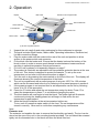
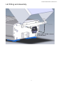
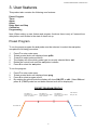
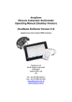
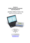
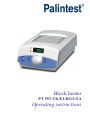
Block heater PT 592 UK/EURO/USA Operating instructions Palintest Manual Part 41281Issue A 2 Palintest Manual Part 41281Issue A Contents 1. Safety 2. Operation 3. User features 4 5 8 8 9 10 10 11 12 13 14 15 16 17 Preset program Timer Alarm Offset Delay start / stop Calibration Programming 4. Maintenance 5. Guarantee and service 6. Specification 7. Compliance 3 Palintest Manual Part 41281Issue A 1. Safety The following symbols mean:Caution: Read these operating instructions fully before use and pay particular attention to sections containing this symbol. Caution: Surfaces can become hot during use. Always observe the following safety precautions Do not check the temperature by touch. Use a thermometer. Do not touch surfaces which become hot during high temperature operation. Use only as specified by the operating instruction or the intrinsic protection may be impaired. To reduce the risk of eye injury during high temperature operation, use safety goggles or spectacles. After transport or storage in humid conditions, dry out the unit before connecting it to the supply voltage. During drying out the intrinsic protection may be impaired. Connect only to a power supply with a voltage corresponding to that on the serial number label at the rear of the unit. Ensure that the mains switch and power plug are easily accessible during use. Connect only to a power supply which provides a safety earth (ground) terminal. Before moving, allow to cool and disconnect at the power supply socket. If liquid is spilt inside the unit, disconnect it from the power supply and have it checked by a competent person. It is the user's responsibility to carry out appropriate decontamination if hazardous material is spilt on or inside the equipment. Clean the unit only with a damp cloth. Do not use chemical cleaning agents. Before using any cleaning or decontamination method except those recommended in this manual, users should check with Palintest Ltd that the proposed method will not damage the equipment. The unit must be placed on a level, non-flammable surface away from flammable materials and ensuring that all ventilation slots in the base are clear from obstructions. Disconnect the mains before removing the outer cover. Note there are no user serviceable parts inside in the unit. Use appropriate vessels / tubes for temperature required. 4 Palintest Manual Part 41281Issue A 2. Operation Display Mains inlet Extractor tool storage bracket Removable block Heater indicator Fault indicator Control knob Mains switch (F)unction & (S)elect buttons 1. 2. Unpack the unit carefully and retain packaging for future shipment or storage. The pack includes: Block heater, Mains cable, Operating instructions, Extractor tool, Lid with connection fittings. 3. Plug the mains cable into the socket at the rear of the unit and position to allow access to the power switch and connector. 4. Fit the block into the heater well. Ensure that the heater bed and the bottom of the block is clean in order to ensure good thermal contact between heater and block resulting in optimal temperature control performance. 5. Fit Lid to unit as shown in lid assembly diagram on page 7. 6. The product is fitted with an adjustable over-temperature protection device at the rear of the unit. This device is designed to protect the sample. To set up the overtemperature cut out refer to the relevant section on page 6. 7. Turn the unit on by pressing the mains switch on the front of the unit. The display will illuminate showing the current temperature of the block. 8. The unit is programmed with a preset program of set point 150°C for 120 minutes which can be accessed and turned on by referring to the preset program in section 4. 9. If the preset program is not required then a set temperature can be set by following items 10 to 12 of this procedure. 10. Press the ‘S’ button and adjust the set temperature using the knob. Press ‘S’ to select the temperature or press ‘F’ to exit without changing the value. 11. The block heater will now begin to heat the block. The heater light will illuminate continuously during the heating phase but will begin to flash when the set temperature is approached. 12. Allow the block to stabilise at the set temperature before use. To turn unit off, press the mains switch on the front. The set temperature will be stored in memory. Allow unit to cool before completing any maintenance Note: Extractor tool: The extractor tool enables the user to remove the block safely and easily. The tool can be stored on the rear of the unit in the mounting bracket provided. The tool should be screwed tightly into the threaded hole in the block and then the block lifted out. 5 Palintest Manual Part 41281Issue A Heating Error Detection If the processor detects an error in heating the fault light will illuminate, the buzzer will beep and the display will flash -ot-. To reset this fault switch the unit off and then on. If the fault re-occurs contact Palintest Ltd. Adjustable Over-Temperature Protection Device The Palintest block heater is fitted with an adjustable over-temperature protection device at the rear of the unit which has been preset at 160°C. This device is designed to protect the sample not the user from harm. If operated it will display the same fault as above. To set the device use the following procedure: a) Turn the knob of the protection thermostat to maximum (clockwise) b) Set the control temperature to 2°C above the desired operating temperature and wait for the temperature to stabilise c) Slowly turn the knob down until a click is heard and -ot- is displayed d) Reset the control temperature to the desired operating temperature Probe Error Detection 1. Err2/Err3 – System Probe (out) failure if this fault occurs contact Palintest Ltd. 6 Palintest Manual Part 41281Issue A Lid Fitting and Assembly Fit bracket with 2 off M3 x 6 screw and 2 x M3 Washers 7 Palintest Manual Part 41281Issue A 3. User features This product also contains the following user features: Preset Program Timer Alarm Offset Delay Start and Stop Calibration Programming Note: When setting up user feature and program functions there is only a 5 second time delay before unit reverts to the start of menu set up. Preset Program To run the preset program the out probe must be selected, to select the out probe, complete the following procedure: 1 2 3 4 5 6 Press F to enter main menu. Rotate control knob until display shows prOb. Press S to select probe selection. The display will show which probe type is currently selected int or out. Rotate the control knob until the out probe is shown. Press S to select the out probe. To run the program: 1 2 3 4 Press F to enter main menu. Rotate control knob until display shows prog. Press S to select program mode. By rotating the control knob the display will show ON OFF or edit. Select ON and press S. (If OUT probe has not been selected err4 will be displayed). PRESET PROGRAM PROFILE SET POINT 1 Temperature (S1) 150ºC Time (T) 120mins SET POINT 2 Temperature (S2) 150ºC Time (T) 0mins SET POINT 3 Temperature (S3) 150ºC Time (T) 0mins END POINT Beep on (S4) HEATER OFF HEATER ON 8 Palintest Manual Part 41281Issue A Timer The timer is used to count down a time period in the range of 1 to 9999 minutes. A buzzer signifies time up, but the heater control is not affected. 1 2 3 4 5 6 7 8 9 Press F to enter main menu. Rotate control knob until display shows CLOC. Press S to select timer control. Display will show ON or OFF. Rotate knob to desired state and press S to select state. If ON is selected the display will flash and show number of minutes. Rotate the control knob until the desired value is displayed and press S to select. If OFF is selected the display will return to the actual temperature. If the timer is set the display will alternate between actual temperature and time left on the timer. Once the timer has counted down to zero the buzzer will sound and the display will alternate between END and actual temperature1. To cancel the buzzer press either F or S key. The buzzer will cancel automatically after 5 minutes. If the main power to the unit fails the timer will revert to OFF2. Notes: 1 The heater control is not affected by the timer, normal operation continues. 2 The timer value will be retained in memory after the main power has been turned off. 9 Palintest Manual Part 41281Issue A Alarm The alarm is a deviation alarm, settable from 0.5 to 10 ºC. If the actual temperature deviates from the set point by more than the value selected the alarm will sound. It is only activated once the actual value has been within ± 0.2 ºC of the set value for 2 minutes. It does not affect the normal operation of the unit. 1 2 3 4 5 6 7 8 9 10 Press F to enter main menu. Rotate control knob until display shows ALAr. Press S to select alarm control. Display will show ON or OFF. Rotate knob to desired state and press S to select. If ON is selected the display will flash and show the current set value. Rotate control knob until desired value is shown. (The alarm limit is ± 0.5oC to ±10.0oC) If OFF is selected the display will return to the actual temperature. Press S to set alarm state once the desired value has been selected. The display will return to actual temperature. No indication is given that the alarm is set. If the temperature is outside the limit set for more than 10 seconds, the buzzer will sound and the display will alternate between actual temperature and -AL-. To reset the alarm press either F or S key. If the alarm conditions still exist the alarm will re-activate after 10 seconds. To disable the alarm feature select OFF at point 4 above. Note: The alarm value and set state condition are retained in memory. Offset The offset feature allows the user to change the temperature by up to ±2 ºC in order to allow single point calibration. 1 2 3 4 5 6 Press F to enter main menu. Rotate control knob until display shows Oset. Press S to select offset control. The display will flash and show current value. Rotate the control knob until desired value is shown. Press S to confirm the offset value. To cancel the offset, set the value to 0.0. 10 Palintest Manual Part 41281Issue A Delay Start and Stop The delay start and stop provides a means of turning the heater control on or off after a specified period of time. 1 2 3 4 5 6 7 Press F to enter main menu. Rotate control knob until display shows deL. Press S to select delay control. Display will show ON or OFF, rotate knob to desired state. Press S to select state. If ON is selected the display will show either strt (delayed start) or StOp (delayed stop). Using the control knob select which type of delay is required. Press S to select. The display will flash and show the number of minutes delay. Rotate the control knob until the desired value is displayed and press S to select. Notes: 1 2 During delayed start the display will alternate between STRT and the actual temperature. During delayed stop the unit will continue to respond as normal. Once the delayed period has expired the temperature control will be turned off and the display will alternate between stop and the actual temperature. To return to normal operation press either the S or F keys. 11 Palintest Manual Part 41281Issue A Calibration The calibration procedure allows the user to calibrate the unit over a wide temperature range. A calibrated thermometer will be required to measure the temperature of the block. The adjusted readings entered must be within ±3ºC of the original reading. 1 2 3 4 5 6 7 8 9 10 11 12 13 14 15 16 17 18 19 20 21 22 Set the temperature of the unit to 35°C in the normal manner and allow the unit to stabilise. Press F to enter main menu. Rotate control knob until display shows CaL. Press S to select calibration. The display will show PASS for one second then O001.Rotate to a value of 0004 and press S to select. Rotate the control knob until the display shows LCAL. Press S to select. The display will show the current temperature value. Using the control knob change the value to match that of the calibrated thermometer. Press S to select the new value. The display will revert to the non-adjusted actual temperature. Set the temperature of the unit to 75°C and allow the unit to stabilise. Press F to enter main menu. Rotate control knob until display shows CaL. Press S to select calibration. The display will show PASS for one second then O001. Rotate to a value of 0004 and press S to select. Rotate the control knob until the display shows HCAL. Press S to select. The display will show the current temperature value. Using the control knob change the value to match that of the calibrated thermometer. N.B. If the reading is over 3 degrees out the unit will continue to flash the display. In this case turn the unit off and allow to cool. Then remove the blocks and clean the heater bed and bottom of the blocks and start the procedure again. Press S to select the new value. The display will revert to the non-adjusted actual temperature. Press F to enter main menu. Rotate control knob until display shows CaL. Press S to select calibration. The display will show PASS for one second then O001. Rotate to a value of 0004 and press S to select. Rotate the control knob until the display shows set. Press S to select. The display will now display the actual adjusted temperature using the calibration values entered. To return to factory settings complete the following: 1 2 3 4 5 Press F to enter main menu. Rotate control knob until display shows CaL. Press S to select calibration. The display will show PASS for one second then O001. Rotate to a value of 0004 and press S to select. Rotate the control knob until the display shows rFd. Press to select. 12 Palintest Manual Part 41281Issue A Programming To set up a program the out probe must be selected, to select the out probe, complete the following procedure: 1 2 3 4 5 6 Press F to enter main menu. Rotate control knob until display shows prOb. Press S to select probe selection. The display will show which probe type is currently selected int or out. Rotate the control knob until out probe is shown. Press S to select the out probe. The Palintest block heater is capable of running a simple program consisting of three temperature and time segments and an end phase. All the temperature/time segments must be set even if only 2 steps are required. 1 2 3 4 5 6 7 8 9 10 11 12 13 14 15 16 17 18 19 20 21 22 Press F to enter main menu. Rotate control knob until display shows prog. Press S to select program mode. Rotate the control knob to show ON OFF or edit. Press S to select state. (On or Off will return the display to actual temperature. On runs the program, Off returns to normal operation). If edit is selected the display will show s1 (section 1) then SEtP (set point). Press S to select edit mode. The display will flash and show the current set value. Rotate the control knob until the desired value is displayed and press S to select. The display will show t (time). Press S to select. The display will flash and show the time in minutes. Rotate the control knob until the desired value is displayed and press S to select. The display will show S2 (section 2). Repeat steps 6 to 10 above for sections 2 and 3. The display will show S4 (section 4), press S to select. The display will show BEEP (buzzer) press S to select. By rotating the control knob the display will show ON or OFF. Press S to select state of buzzer when the program finishes (it will sound for 1 minute). The display will show HEAt (heater control). Press S to select. By rotating the control knob the display will show ON or OFF. Press S to select state of heater control when the program finishes. If Off is selected the heater is switched off after the last step and there is no temperature control. If On is selected the unit will return to normal operation. The unit is now programmed; to run the program: Press F to enter main menu. Rotate control knob until display shows prog. Press S to select program mode. By rotating the control knob the display will show ON OFF or edit. Select On and press S. (If OUT probe is not selected err4 will be displayed). To cancel the program complete steps 18 to 21 but select Off. Notes: 1. When running a program the display will alternate as follows: When heating up the display will alternate between STP and the actual temperature. When temperature has been achieved and stabilized the display will alternate between time left, step number and actual temperature. 2. The time count down for each step is only started once the actual temperature is within 1 ºC of the set temperature. 13 Palintest Manual Part 41281Issue A 4.Maintenance All products covered in this manual are designed to comply with IEC61010-1 and can be flash tested. Some are fitted with radio frequency interference suppressers. Therefore it is recommended that only a D.C. test be performed. No other routine service is required. Cleaning The case can be cleaned with a damp cloth after disconnection. Do not use solvents. Before using any decontamination or cleaning method except that recommended, check with our Service Department that the proposed method will not damage the equipment. Replacement of fuses Disconnect from the power supply socket. Remove the IEC power plug from the rear of the unit. Pull out the fuse drawer, replace the fuse with the correct type, and replace the fuse holder. The fuses are ceramic quick acting, rated: Voltage Model Fuse Rating (Amps) Voltage Model Fuse Rating (Amps) 230V 230V PT 592 UK PT 592 EU 2 2 120V PT 592 USA 3.15 14 Palintest Manual Part 41281Issue A 5.Guarantee and Service Guarantee When used in laboratory conditions and according to these working instructions, this product is guaranteed for THREE YEARS against faulty materials or workmanship. Service There are no user serviceable parts inside the unit. For service return for repair to our Service Department. Please do not return the blocks. Service Address: Service Department Palintest Ltd Palintest House Team Valley Gateshead Tyne & Wear NE11 0NS England. Tel: +44 (0) 191 491 0808 Fax: +44 (0) 191 482 5372 E-mail: [email protected] Web: www.palintest.com 15 Palintest Manual Part 41281Issue A 6.Specification Supply Specifications Voltage Frequency PT 592 UK 230V UK PLUG PT 592 EU 230V EURO PLUG 230V 10% 230V 10% 50-60Hz 50-60 Hz PT 592 USA 120V USA PLUG 120V 10% 50-60Hz Minimum Setting Temperature ºC Max Temperature ºC Stability @ 37 ºC within block Uniformity @ 37 ºC within block Number of blocks Setting resolution ºC Display resolution ºC Adjustable over temperature cut out Heat up time 25 to 100 ºC minutes Width x height mm Model variations 15 200 ±0.1 ±0.1 1 0.1 0.1 yes 15 200 x100 PT 592 UK PT 592 EU PT 592 USA Block variations Length Block Size 140 x 100 Heater power (watts) 230/110V 300/200 The block heater is fitted with a thermal fuse which operates at a temperature of 230°C. 16 Palintest Manual Part 41281Issue A 7.Compliance WEEE Directive In Europe, at the end of its life the product must be disposed of in accordance with the WEEE directive, For information regarding WEEE collections in the UK please contact our B2B Compliance Scheme directly on 01691 676 124 Our supplier complies fully with the Waste Electrical & Electronic Equipment (WEEE) regulations 2006. They are a member of the B2B compliance scheme (Scheme Approval Number WEE/MP3338PT/SCH), which handle the WEEE obligations on the behalf of our supplier have been issued with a unique registration number by the Environmental Agency; this reference number is WEE/GA0048TZ. For other countries please contact your equipment supplier. For General WEEE information please visit: www.b2bcompliance.org.uk RoHS Directive All the products covered by this manual comply with the requirements of the RoHS Directive (Directive 2002/95/EC). This means the products are free of Lead and other hazardous substances covered by the directive. Electrical safety and Electromagnetic compatibility All the products covered by this manual comply with the requirements of the Low Voltage Directive (2006/95/EC) for Electrical safety and the EMC directive (2004/108/EC) for Electromagnetic compatibility. See the Declaration of Conformity on the inside back page 17 Palintest Manual Part 41281Issue A Palintest Ltd Palintest House Kingsway Team Valley Gateshead Tyne and Wear NE11 0NS England 18