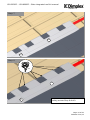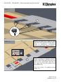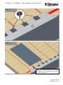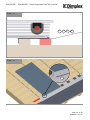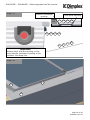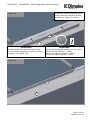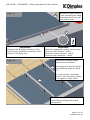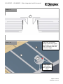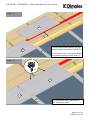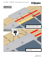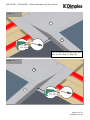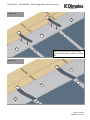
1
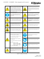
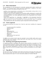
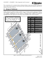
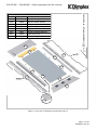
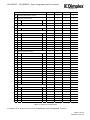
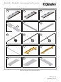
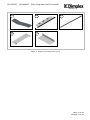
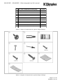
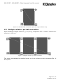
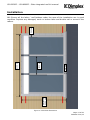
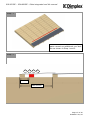
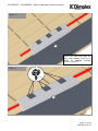
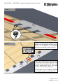
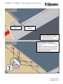
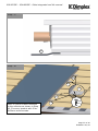
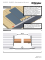
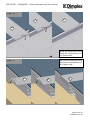
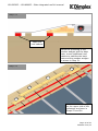
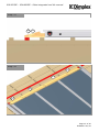
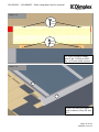
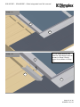
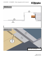
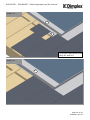
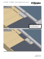
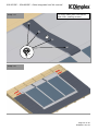
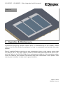
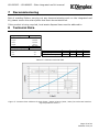
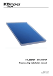
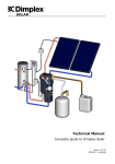
SOLAR
SOL202SIP – SOL808SIP
Slate Integrated Roof Kit
Installation Manual
Page 1 of 60
R02894-2 – 01/14
SOL202SIP – SOL808SIP - Slate integrated roof kit manual
SOLAR
0
Contents
0
CONTENTS
2
1
BEFORE YOU START
3
1.1
1.2
1.3
1.4
1.5
1.6
1.7
GENERAL
COMPETENCE
HEALTH AND SAFETY
RISK ASSESSMENT
TOOLS REQUIRED
EARTHING AND LIGHTNING PROTECTION
PIPE WORK
3
3
3
5
5
5
5
2
SCOPE OF DELIVERY
3
PRODUCT FEATURES AND DESCRIPTIONS
12
4
COLLECTOR CONNECTIONS
12
4.1 SINGLE COLLECTOR PORTRAIT CONNECTION
4.2 MULTIPLE COLLECTOR PORTRAIT CONNECTION
6
12
13
INSTALLATION
14
5
OPERATION & MAINTENANCE
56
6
SPARE PARTS
57
7
DECOMMISSIONING
58
8
TECHNICAL DATA
58
Page 2 of 60
R02894-2 01/14
SOL202SIP – SOL808SIP - Slate integrated roof kit manual
SOLAR
1
1.1
Before you start
General
Thank you for choosing a Dimplex product. We ensure you that every effort has been
made at the design, manufacture and delivery stages to produce a product with superior quality. We will provide you with the best possible support throughout the product’s
lifespan.
As part of ongoing product development and improvement Dimplex reserves the right to
undertake changes to the product without prior notice. Great care has been taken to
ensure this manual was correct at the time of print. Should you however discover any
issues with the information contained therein please do not hesitate to contact your
vendor.
We strongly recommend reading the whole contents of this manual before commencing
the work.
1.2
Competence
Dimplex products have been designed and manufactured to the current relevant standards and under stringent quality control procedures. It is therefore imperative that the
product is only installed by a:
- trained and
- competent
person as defined in the relevant regulations. Dimplex does not accept any liability for
damage done to persons or property resulting from undue handling and usage of this
product.
All regulations current at the time of installation are to be considered alongside the content of this manual as they form the code of best practice.
The warranty of this product is linked to the ability to prove that the product was installed, commissioned and maintained:
- by a competent person
- in accordance with Dimplex instructions and the current relevant regulations and legislation
- the product being registered with Dimplex at the time of installation using the form in
the Dimplex On Site Guide
- records showing the date of maintenance in accordance with the maintenance schedule as detailed in the On Site Guide
1.3
Health and Safety
The installation of this product is subject to the Health and Safety at Work Act. It is
your responsibility to ensure that the transport, storage, installation and operation of
the product is carried out in a safe manner.
Dimplex will not accept any liability due to damage caused to people or property resulting from negligence or not adhering to the relevant Health and Safety practices.
Page 3 of 60
R02894-2 01/14
SOL202SIP – SOL808SIP - Slate integrated roof kit manual
SOLAR
Safety precautions: Before commencing mounting
work on roofs, it must be ensured in all cases that the
non- personal fall protection and fall-arrest systems
required by DIN 18338 (Roof Covering and Roof
Sealing Works) and DIN 18451 (Scaffolding Works) are
in place. See also Builders‘ Protection Ordinance
[Bauarbeiterschutzverordnung], Federal Law Gazette
340/ 1994, paragraphs 7-10! Other country-specific
regulations must be observed!
Safety harnesses should be fixed above the users
whenever possible. Safety harnesses should only
be fastened to sufficiently load-bearing structures
or fixing points!
If non-personal fall protection or fall-arrest systems
cannot be installed for technical reasons, all
personnel must be secured by means of suitable
safety harnesses!
Never use damaged ladders (e.g., wooden ladders
with split runners or rungs, or bent or buckled
metal ladders). Never try to repair broken runners,
rungs or steps on wooden ladders!
Only use safety harnesses (safety belts, lanyards and
straps, shock absorbers, fall arresters) that were
tested and certified by authorized testing bodies.
Ensure that ladders are put up safely. Observe the
correct leaning angle (68° - 75°). Prevent ladders
from sliding, falling over or sinking into the ground
(e.g. using wider feet, feet suited to the ground or
hooking devices).
If non-personal fall protection or fall-arrest systems
are not provided, working without the use of
suitable safety harnesses may lead to falls from
heights and therefore cause serious or lethal
injuries!
Only lean ladders against secure points. Secure
ladders in traffic areas by suitable cordoning.
Ladders not properly secured against sinking in,
sliding or falling over may lead to dangerous falls!
Contact with live electric overhead cables can be
lethal.
Whenever you are near live overhead electric cables
where contact is possible, only work if:
Wear protective goggles when drilling and
handling collectors!
- it is ensured that they are voltage-free and this
is secured for the duration of work.
- the live parts are secured by covering them or
cordoning them off.
- the prescribed safety distances are maintained.
Voltage radius:
1 m ................voltages up to 1000V
2 m ................voltages from 1000V to 11000V
3 m ................voltages from 11000V to 22000V
4 m ................voltages from 22000V to 38000V
> 5 m in case of unknown voltages
The manufacturer hereby guarantees to take back
products identified with an eco-label and to recycle
the materials used. Only the heat transfer medium
specified may be used!
Wear safety shoes when carrying out installation
work!
Wear cut-proof safety gloves when mounting
collectors!
Wear a helmet when carrying out installation
work!
Figure 1: Safety information
Page 4 of 60
R02894-2 01/14
SOL202SIP – SOL808SIP - Slate integrated roof kit manual
SOLAR
1.4
Risk assessment
The compilation of a risk assessment is strongly recommended before installing the
product. The following areas require particular consideration in addition to the information required by the Health and Safety at Work Act.
- scalding: where appropriate or required by law a thermostatic mixing valve is to be
fitted to the hot water outlet of the cylinder
- explosion: the unit is fully equipped with all relevant safety equipment to comply with
current regulations. The correct design and function has been verified by independent
third party testing. The correct application thereof is the responsibility of the competent installer.
- water borne organisms (i.e. Legionella): if applicable a risk assessment should be
carried out following the recommendations outlined in the Approved Code of Practice
L8.
- the user preference must be considered when commissioning the system, in particular
when adjusting the solar and auxiliary system temperature and timer settings.
1.5
Tools required
It is recommended that the below list of tools be used when installing the integrated
roof kit.
-
2 people required for installation
Measuring tape
Hammer
Drill
Adjustable pliers
TX 25 x 25mm torque bit
Spirit level
Plumb line
Additional wood (as required)
Pop-rivet gun
In addition to the above tools it may be required to wear suitable safety gloves upon
installation as the kit consists of sheet metal which may cause cuts if care is not taken
during handling of the product.
1.6
Earthing and Lightning Protection
If a lightning arrester is available, the collector frame should be connected to it. This
may be performed using the collector frame, because the slot for mounting on the reverse side of the collector is ideally suited for fixing a thick cable. If no arrester is available, the potential equalization is carried out using a connection of a cable at the
pipe(s) which are led into the building. Please consult local regulations to ensure adherence.
1.7
Pipe Work
The pipe work from the collector to the pump unit and from the pump unit to the cylinder is to be all metal. The joints have to be high temperature resistant (compression or
high temperature flat seal). For more information please see Technical Manual.
Page 5 of 60
R02894-2 01/14
SOL202SIP – SOL808SIP - Slate integrated roof kit manual
SOLAR
The connections of a mounted solar collector/collector array may become excessively
hot so care must be taken to avoid burns when working around collectors that are exposed to the rays of the sun.
2
Scope of delivery
Please check the contents and the condition of your delivery before signing the delivery
documentation against the content shown in Table 3 and mark as appropriate. Contact
your supplier immediately for any missing or damaged parts. Claims for missing or
damaged parts after signing for the delivery documentation will not be accepted.
Part No.
P31
P32
P33
P34
P35
P36
P37
P38
P39
P40
P41
P42
P43
P44
P45
P46
P47
P51
SOL202COL
Spare No. Description
74021
left front part
74022
centre front part
74023
right frontpart
74220
lateral fixation bracket
74222
centre fixation bracket
74211
left lateral part
74213
right lateral part
74001
left collector cover
74002
centre collector cover
74003
right collector cover
74230
connection strip
74090
wooden wedge 600 mm
74091
wooden wedge 1200 mm
74061_SL left back part
74062
centre back part
74063_SL right back part
74070
back part connection
74224
slate lateral part
Useable from 20° roof pitch!
These mounting instructions
only apply to the installation of
the in roof flashing and the
fixation of the collectors!
Table 1: Overview of flashing components part 1
Page 6 of 60
R02894-2 01/14
SOL202SIP – SOL808SIP - Slate integrated roof kit manual
SOLAR
SOL202COL
Spare No. Description
74024
front part single collector
74220
lateral fixation bracket
74211
left lateral part
74213
right lateral part
74004
single collector cover
74091
wooden wedge 1200 mm
74224
slate lateral part
74064_SL back part single collector
Useable from 20° roof pitch!
Part No.
P48
P34
P36
P37
P49
P43
P51
P50
P50
P43
P51
P37
P34
P36
P51
P34
P49
P48
P34
Table 2: Overview of flashing components part 2
Page 7 of 60
R02894-2 01/14
SOL202SIP – SOL808SIP - Slate integrated roof kit manual
SOLAR
No. Designation
SOL202SIP
SOL404SIP
SOL606SIP
SOL808SIP
A
Solar flat plate collector 2.02m²
1
2
3
4
B
Hydraulic connection set
1
1
1
1
0
1
2
3
1
0
0
0
0
1
1
1
0
0
1
2
C
P01
22mm x 90° elbow
x2
P02
22mm stop end
x2
Hydraulic interconnection set
P03
#O
P
Q
22mm x 22mm straight compression
Slate integrated set 2.02m²
P48
front part single collector
P34
lateral fixation bracket
P49
single collector cover
P36
left lateral part
P37
right lateral part
P43
wooden wedge 1200mm
P50
back part single collector
P51
slate lateral part
Slate integrated set 4.02m²
P31
left front part
P33
right front part
P34
lateral fixation bracket
P35
centre fixation bracket
P38
left collector cover
P40
right collector cover
P36
left lateral part
P37
right lateral part
P41
connection strip
P42
wooden wedge 600mm
P43
wooden wedge 1200mm
P44
left back part
P46
right back part
P47
back part connection
Slate integrated set extension
P32
centre front part
P35
centre fixation bracket
P39
centre collector cover
P41
connection strip
P43
wooden wedge 1200mm
P45
centre back part
P47
back part connection
x2
Table 3: Scope of components
# Letters D to N are for On-Roof Installation and Integrated Tile kits
Page 8 of 60
R02894-2 01/14
SOL202SIP – SOL808SIP - Slate integrated roof kit manual
SOLAR
P31
P32
P33
P34
P36
P37
P38
P39
P40
P41
P42
P43
14
P44
16
P45
17
P46
P35
5
Table 4: Images of components part 1
Page 9 of 60
R02894-2 01/14
SOL202SIP – SOL808SIP - Slate integrated roof kit manual
SOLAR
P47
18
21
P50
P48
19
20
P49
P51
Table 5: Images of components part 2
Page 10 of 60
R02894-2 01/14
SOL202SIP – SOL808SIP - Slate integrated roof kit manual
SOLAR
No. Art. Code +74357 Generic fitting bag
Content
1
Sealing screw 4.5 x 25mm anthracite
2
Torque bit TX25 x 25mm
34
3
Fixation bracket (for lateral parts)
10
4
Galvanised nails 2.5 x 25mm
60
5
Rivet anthracite 4.1mm
6
C hipboard screw SK TX25 5.0 x 30mm
7
C hipboard screw TX25 5.0 x 50mm
6
8
C hipboard screw TG SK TX25 5.0 x 70mm
6
9
Lateral fixation bracket (for collector)
8
10
C entre fixation bracket (for collector)
4
1
2
32
Table 6: Scope of components for generic bag of fittings
Table 7: Images of components in generic bag of fittings
Page 11 of 60
R02894-2 01/14
SOL202SIP – SOL808SIP - Slate integrated roof kit manual
SOLAR
3
Product features and descriptions
The Dimplex Slate Integrated Roof kit offers a unique solution for mounting solar thermal collectors to the roof of a building. The concept of the product is to make the installation of the collectors a quick and simple process.
The Slate Integrated Roof Kit can cater for 2m² up to 8m² of collector area and comes
in three variations, 2m² kit, 4m² kit and extension kit.
The product consists of various aluminium flashings and fixings that seal the collector
against the roof covering in an aesthetically pleasing way. The collector is an integral
part of the assembly and forms part of the weather tightness of the roof.
4
Collector connections
Due to its four connections, the collector offers a wide choice of connection options.
Ensure that no part of the collector array or collector in the array is short circuited by
following these instructions.
When planning the collector array, the position of the various connection parts must be
in accordance with the diagrams, also pay attention to the position of the highlighted
sensor pocket position.
Table 8 illustrates the components required to make all the collector connections.
Part No
Image
Description
P01
22mm x 90° elbow
P02
22mm stop end
P03
22mm x 22mm straight compression
Table 8: Collector connection components
4.1
Single collector portrait connection
When installing a single collector installation, there is one connection option available.
The sensor must always be installed at the top of the collector and on the connection
where the heat transfer fluid leaves the collector.
Figure 2 illustrates the left hand side connection option that is applicable only to a single portrait collector connection.
Page 12 of 60
R02894-2 01/14
SOL202SIP – SOL808SIP - Slate integrated roof kit manual
SOLAR
Figure 2: Left hand side connection option for single collector only
4.2
Multiple collector portrait connection
When installing multiple collectors, (2 up to 4), component P03 is used to connect one
collector to the next.
Figure 3: Multiple collector portrait connection
The sensor must always be installed at the top of the collector on the connection flow of
the system.
Page 13 of 60
R02894-2 01/14
SOL202SIP – SOL808SIP - Slate integrated roof kit manual
SOLAR
Installation
SOL202COL
2390 mm
200 mm
1225 mm
4100 mm
240 mm
NB: Ensure all the laths / roof battens under the area of the installation are in good
condition. Replace any damaged, week or broken laths and double nail or screw to the
rafters.
Figure 4: Mounted dimensions
Page 14 of 60
R02894-2 01/14
SOL202SIP – SOL808SIP - Slate integrated roof kit manual
SOLAR
Step: 1
For the stabilisation of the front
parts mount an additional roof batten as shown in Step 1 and 2.
Step: 2
P31
P32
P33
P48
90 mm
280-300mm
Page 15 of 60
R02894-2 01/14
SOL202SIP – SOL808SIP - Slate integrated roof kit manual
SOLAR
Step: 3
P31
Place the left front part on
the roof batten and fix it
with 12 sealing screws
(Step 4 and 5).
Step: 4
6x
P31
Page 16 of 60
R02894-2 01/14
SOL202SIP – SOL808SIP - Slate integrated roof kit manual
SOLAR
Step: 5
P31
6x
Ensure the aluminium edges of both
parts are well aligned and the apron
forms a continuous overlapping
barrier to avoid any water ingress.
Step: 6
P31
P32
P32
P31
Place the centre front part on the
roof batten and plug it together with
the left front part until the first hole
on the centre part fits to the right
hole on the left part (Step 6).
In the case of a 2-collector installation please continue with Step 10.
Page 17 of 60
R02894-2 01/14
SOL202SIP – SOL808SIP - Slate integrated roof kit manual
SOLAR
Step: 7
P32
P31
Step: 8
6x
P32
P31
Fix the centre front part with 12
sealing screws Step 8 and 9.
Page 18 of 60
R02894-2 01/14
SOL202SIP – SOL808SIP - Slate integrated roof kit manual
SOLAR
Step: 9
P32
6x
Ensure the aluminium edges of both
parts are well aligned and the apron
forms a continuous overlapping
barrier to avoid any water ingress.
Step: 10
P32
P33
P33
P32
Place the right front part on the roof
batten and plug it together with the
centre (left) front part until the first
hole on the right front part fits to
the right hole on the centre front
part (Step 10).
Then fix it with 12 sealing screws
(Step 11).
Page 19 of 60
R02894-2 01/14
SOL202SIP – SOL808SIP - Slate integrated roof kit manual
SOLAR
Step: 11
12 x
P33
Step: 12
Place the first collector. Fit it into
the flaps on the front part as shown
in Step 13 and 14.
Page 20 of 60
R02894-2 01/14
SOL202SIP – SOL808SIP - Slate integrated roof kit manual
SOLAR
Step: 13
P31
P32
P33
P48
Step: 14
P31
Page 21 of 60
R02894-2 01/14
SOL202SIP – SOL808SIP - Slate integrated roof kit manual
SOLAR
Step: 15
Marking for
slate
Marking for
collector
Place the collector so that it
is aligned with the marking
on the left front part.
Fix the collector on the left
(outer) side with 4 lateral fixation
brackets.
Place the brackets to the collector
as shown in Step 17 and fix every
lateral fixation bracket with 2 No.
5x30mm wood screws.
Step: 16
P34
P34
P34
5x30
mm
P34
P34
Page 22 of 60
R02894-2 01/14
SOL202SIP – SOL808SIP - Slate integrated roof kit manual
SOLAR
Step: 17
P34
Step: 18
P35
P35
P35
P35
Place 4 centre fixation brackets
to the collector as shown in Step
19. Fix every bracket with 2 No.
5x30mm wood screws.
P35
5x30
mm
Page 23 of 60
R02894-2 01/14
SOL202SIP – SOL808SIP - Slate integrated roof kit manual
SOLAR
Step: 19
P35
Step: 20
P03
P03
Position 22 x 22mm straight
compression fittings on 1st collector
loosely before fitting 2nd collector.
Page 24 of 60
R02894-2 01/14
SOL202SIP – SOL808SIP - Slate integrated roof kit manual
SOLAR
Allow the 2nd collector to rest into the
flaps offset slightly to the right. Gently
taking the weight off the collector,
move it to the left, ensuring the collector engages in the centre fixation
brackets of the 1st collector (Step 22)
and into the flaps of the centre front
part (Step 13) and the loosely fitted
compression fittings (Step 20).
Step: 21
The distance between the collectors
should be about 55mm and this should
ensure a neat fit with the centre fixation brackets (Step 22).
Step: 22
55mm
P35
Page 25 of 60
R02894-2 01/14
SOL202SIP – SOL808SIP - Slate integrated roof kit manual
SOLAR
Step: 23
Step: 24
P35
5x30
mm
Fix every centre fixation bracket
with 2 additional 5x30mm wood
screws.
Page 26 of 60
R02894-2 01/14
SOL202SIP – SOL808SIP - Slate integrated roof kit manual
SOLAR
Step: 25
P35
P35
P35
P35
Place 4 centre fixation brackets
on the right side of the 2nd collector (Step 19) and fix every
bracket with 2 No. 5x30mm
wood screws.
5x30
mm
P35
Step: 26
P03
P03
Position 22 x 22mm straight compression fittings on 2nd collector
loosely before fitting 3rd collector.
Page 27 of 60
R02894-2 01/14
SOL202SIP – SOL808SIP - Slate integrated roof kit manual
SOLAR
Repeat steps 20 to 24
Step: 27
Step: 28
P35
5x30
mm
Page 28 of 60
R02894-2 01/14
SOL202SIP – SOL808SIP - Slate integrated roof kit manual
SOLAR
Step: 29
Fix the right (outer) side of the
collector with 4 lateral fixation
brackets.
P34
P34
P34
P34
P34
5x30
mm
P34
Fit collector connections and sensor
and pressure test and insulate.
Step: 30
P01
sensor
P36
P02
Page 29 of 60
R02894-2 01/14
SOL202SIP – SOL808SIP - Slate integrated roof kit manual
SOLAR
Fit the left lateral part to the collectors profile as shown in Step 32.
Step: 31
On the lower side the upper perforation should be aligned with the collectors profile as shown in Step 34.
P36
Step: 32
P36
Page 30 of 60
R02894-2 01/14
SOL202SIP – SOL808SIP - Slate integrated roof kit manual
SOLAR
Step: 33
P36
P31
Step: 34
P36
Align the upper perforation
with the collector edge!
P31
Bend the lateral part along
the perforation as shown
in Step 34 and 35.
Page 31 of 60
R02894-2 01/14
SOL202SIP – SOL808SIP - Slate integrated roof kit manual
SOLAR
Step: 35
P36
P31
Step: 36
P36
P31
Page 32 of 60
R02894-2 01/14
SOL202SIP – SOL808SIP - Slate integrated roof kit manual
SOLAR
Fix the left lateral part with
a nail on every roof batten.
Step: 37
P36
P36
P31
Step: 38
P02
P01
Fit collector connections and pressure test and insulate.
Page 33 of 60
R02894-2 01/14
SOL202SIP – SOL808SIP - Slate integrated roof kit manual
SOLAR
Mount the right lateral part
in the same way as the left
one.
Step: 39
P37
P33
Mount the left collector cover
and fit into the collector profile
as shown in Step 41 and 42.
Step: 40
P36
P38
P31
Important!
Check the engraved number on the cover.
Cover for left collector: 74001
Cover for centre collector: 74002
Cover for right collector: 74003
Page 34 of 60
R02894-2 01/14
SOL202SIP – SOL808SIP - Slate integrated roof kit manual
SOLAR
Step: 41
Collector ventilation
opening
Cover parts opening
Step
41a
P38
P39
P40
P38
P39
P40
P49
P49
P31
P32
P33
P48
Important!
Always check that the opening on the
cover fits the ventilation opening of the
collector. See Step 41a.
Step: 42
P38
P36
P31
Page 35 of 60
R02894-2 01/14
SOL202SIP – SOL808SIP - Slate integrated roof kit manual
SOLAR
Mount the centre collector cover
and fit into the collector profile
as shown in Step 41 and 44.
Step: 43
P39
P32
Important!
Always check that the opening on the
cover fits the ventilation opening of the
collector. See Step 41a.
Important!
Check the engraved number on the cover.
Cover for left collector: 74001
Cover for centre collector: 74002
Cover for right collector: 74003
Step: 44
P39
P32
Page 36 of 60
R02894-2 01/14
SOL202SIP – SOL808SIP - Slate integrated roof kit manual
SOLAR
Step: 45
P37
Mount the right collector
cover following the same
procedure as for the left
and centre cover
P33
P40
Important!
Always check that the opening on the
cover fits the ventilation opening of the
collector. See Step 41a.
Important!
Check the engraved number on the cover.
Cover for left collector: 74001
Cover for centre collector: 74002
Cover for right collector: 74003
Mount the collection strips
between the collectors.
Step: 46
P41
P41
Just plug them into the collector profiles as shown in Step
47.
You can use the connection
strips in both directions (there
is no upper or lower side).
Important!
Before fitting insulate pipes and
connections
Page 37 of 60
R02894-2 01/14
SOL202SIP – SOL808SIP - Slate integrated roof kit manual
SOLAR
Step: 47
P41
Step: 48
11
P41
Place the connection
strips so that the upper
perforation on the lower
side is aligned with the
collectors edge.
P41
11
P41
11
Align upper
perforation
with collectors
edge!
Page 38 of 60
R02894-2 01/14
SOL202SIP – SOL808SIP - Slate integrated roof kit manual
SOLAR
Step: 49
P41
11
11
P41
P41
11
Bend the connection strip
along the perforations on
the lower side.
Bend the connection strip
along the perforations on
the upper side.
Step: 50
11
P41
11
P41
11
P41
Page 39 of 60
R02894-2 01/14
SOL202SIP – SOL808SIP - Slate integrated roof kit manual
SOLAR
Step: 51
Additional
roof battens
Before the mounting of the
wooden wedges and the back
parts, mount additional roof
battens to stabilise the back
parts and the wooden wedges
as shown in Step 51.
Step: 52
12
P42
13
P43
P43
13
12
P42
Place the wooden wedges
on the upper side of the
collectors as shown in
Steps 53 and 54.
Page 40 of 60
R02894-2 01/14
SOL202SIP – SOL808SIP - Slate integrated roof kit manual
SOLAR
Step: 53
P42
13
P43
Step: 54
12
P42
13
P43
13
P43
12
P42
Page 41 of 60
R02894-2 01/14
SOL202SIP – SOL808SIP - Slate integrated roof kit manual
SOLAR
Step: 55
5x50
mm
5x70
mm
Fix every wooden wedge
with 2 No. 5x50mm and 2
No. 5x70mm wood screws.
Step: 56
P36
6
P31
1
Cover the left front part
with soakers (Step 56 and
57).
Page 42 of 60
R02894-2 01/14
SOL202SIP – SOL808SIP - Slate integrated roof kit manual
SOLAR
Step: 57
P36
6
P31
1
Step: 58
P36
6
Fit the slate lateral part
into the left lateral part as
shown in Step 59 and
place it as shown in Step
60.
14
P51
P31
1
Page 43 of 60
R02894-2 01/14
SOL202SIP – SOL808SIP - Slate integrated roof kit manual
SOLAR
Step: 59
P36
P51
Soaker
Step: 60
P36
6
P51
14
Fix the slate lateral part with a
nail on the roof batten.
Page 44 of 60
R02894-2 01/14
SOL202SIP – SOL808SIP - Slate integrated roof kit manual
SOLAR
Step: 61
P36
6
14
P51
Cover the slate lateral part
(Step 61 and 62).
Step: 62
P36
6
Page 45 of 60
R02894-2 01/14
SOL202SIP – SOL808SIP - Slate integrated roof kit manual
SOLAR
Step: 63
P36
6
14
P51
Repeat steps 58-62 until
you reach the top of the
lateral part (Step 66).
Step: 64
P36
6
P51
14
Page 46 of 60
R02894-2 01/14
SOL202SIP – SOL808SIP - Slate integrated roof kit manual
SOLAR
Step: 65
P36
6
Step: 66
Page 47 of 60
R02894-2 01/14
SOL202SIP – SOL808SIP - Slate integrated roof kit manual
SOLAR
Step: 67
P36
6
14
P51
If necessary to avoid a collision with the left back part,
cut the last slate lateral part
with a plate shear (Step 67).
Step: 68
P37
7
P33
3
Mount the right side in the
same way as the left one.
Page 48 of 60
R02894-2 01/14
SOL202SIP – SOL808SIP - Slate integrated roof kit manual
SOLAR
Fit the left back part to the collectors profile as shown in Step 70
and place it as shown in Step 71.
Step: 69
P44
15
P36
6
Step: 70
P44
P45
P46
P50
Page 49 of 60
R02894-2 01/14
SOL202SIP – SOL808SIP - Slate integrated roof kit manual
SOLAR
Step: 71
P44
15
P36
6
Step: 72
3x
15
P44
P36
6
Fit the left back part with 3 No.
sealing screws.
Page 50 of 60
R02894-2 01/14
SOL202SIP – SOL808SIP - Slate integrated roof kit manual
SOLAR
Step: 73
16
P45
Fit the centre back part to the collectors profile as shown in Step 70.
15
P44
11
P41
In the case of a 2 collector installation please continue with Step 75.
Step: 74
2x
P45
16
15
P44
P41
11
Fix the centre back part with 2
No. sealing screws.
Page 51 of 60
R02894-2 01/14
SOL202SIP – SOL808SIP - Slate integrated roof kit manual
SOLAR
Step: 75
P46
17
P37
7
16
P45
P41
11
Fit the right back part to the collectors profile as shown in Step 67
and place it as shown in Step 73.
Step: 76
2x
P37
7
P46
17
16
P45
Fit the right back part with 3 No.
sealing screws.
Page 52 of 60
R02894-2 01/14
SOL202SIP – SOL808SIP - Slate integrated roof kit manual
SOLAR
Step: 77
15
P44
4
P36
6
+
Fix the left and the right back part
with a rivet (Step 77 and 78).
Step: 78
17
P46
P37
7
+
Page 53 of 60
R02894-2 01/14
SOL202SIP – SOL808SIP - Slate integrated roof kit manual
SOLAR
Step: 79
P47
18
17
P46
18
P47
16
P45
11
P41
15
P44
11
P41
Place the back part connections
on the back part as shown in Step
80.
Step: 80
P47
18
17
P46
11
P41
16
P45
P47
18
15
P44
P41
11
Page 54 of 60
R02894-2 01/14
SOL202SIP – SOL808SIP - Slate integrated roof kit manual
SOLAR
Fix every back part connection
with 4 No. sealing screws.
Step: 81
18
P47
4x
Step: 82
Page 55 of 60
R02894-2 01/14
SOL202SIP – SOL808SIP - Slate integrated roof kit manual
SOLAR
Step: 83
5
Operation & Maintenance
Connections should be double checked prior to commissioning of the system. Please
refer to the On Site Guide for guidance on how to commission and operate the solar
system.
Risk of scalding! Before carrying out any maintenance work on the system ensure that
it is safe to do so. The solar system must be decommissioned before work can be carried out. Refer to the On Site Guide for a maintenance schedule of the complete system.
Check for leaks at the collector connections and other connections in the system. Also
ensure pipe insulation is intact and in good condition.
Page 56 of 60
R02894-2 01/14
SOL202SIP – SOL808SIP - Slate integrated roof kit manual
SOLAR
6
Spare Parts
Part No.
P31
P32
P33
P34
P35
P36
P37
P38
P39
P40
P41
P42
P43
P44
P45
P46
P47
P48
P49
P50
P51
R02894-1
SOL202COL
Spare No. Description
74021
left front part
74022
centre front part
74023
right frontpart
74220
lateral fixation bracket
74222
centre fixation bracket
74211
left lateral part
74213
right lateral part
74001
left collector cover
74002
centre collector cover
74003
right collector cover
74230
connection strip
74090
wooden wedge 600 mm
74091
wooden wedge 1200 mm
74061_SL left back part
74062
centre back part
74063_SL right back part
74070
back part connection
74024
front part single collector
74004
single collector cover
74064_SL back part single collector
74224
slate lateral part
R02894-1 manual
74357
bag of fittings
Table 9: Spare Parts
Page 57 of 60
R02894-2 01/14
SOL202SIP – SOL808SIP - Slate integrated roof kit manual
SOLAR
7
Decommissioning
Risk of scalding! Before carrying out any decommissioning work on the integrated roof
kit, please ensure the solar system has been decommissioned.
If the product is being recycled, local waste disposal laws must be adhered to.
8
Technical Data
Weight empty
33 kg
Dimensions
- length
1730mm
- width
1170mm
- height
Heat transfer medium
Max op. pres. [bar]
83mm
SOLHT20
10
Tilt angle
Collector array [m²]
2
4
6
8
- min
20°
Cu pipe [mm]
15
15
22
22
- max
75°
Wind / snow load [kN/m²]
1.9
1.9
1.9
1.9
Table 10: Collector technical data
Figure 5: Pressure loss collector for anti-freeze / water mixture (40% / 60%) at a thermal conducting temperature of 50° C.
Page 58 of 60
R02894-2 01/14
SOL202SIP – SOL808SIP - Slate integrated roof kit manual
SOLAR
Page 59 of 60
R02894-2 01/14
SOL202SIP – SOL808SIP - Slate integrated roof kit manual
SOLAR
Page 60 of 60
R02894-2 01/14