1
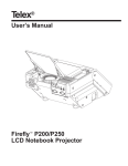
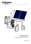
SOLAR SOL202FSP – SOL808FSP Freestanding installation manual Page 1 of 28 R02887-1 10/13 SOL202FSP – Freestanding installation manual SOLAR 0 Contents 0 CONTENTS 2 1 BEFORE YOU START 3 1.1 GENERAL 1.2 COMPETENCE 1.3 HEALTH AND SAFETY 1.4 RISK ASSESSMENT 1.5 TOOLS REQUIRED 1.6 STRUCTURAL REQUIREMENTS 1.7 EARTHING AND LIGHTNING PROTECTION 1.8 CONNECTIONS 1.9 PIPE WORK 1.10 GUARANTEE 3 3 4 5 5 5 6 6 7 7 2 SCOPE OF DELIVERY 3 PRODUCT FEATURES AND DESCRIPTIONS 10 4 RECOMMENDATIONS FOR ATTACHMENT POINTS 13 5 COLLECTOR CONNECTIONS 15 5.1 SINGLE COLLECTOR PORTRAIT CONNECTION 5.2 MULTIPLE COLLECTOR PORTRAIT CONNECTION 8 15 16 6 INSTALLATION 17 7 OPERATION 27 7.1 7.2 7.3 7.4 7.5 FLUSHING AND FILLING INSTALLING THE TEMPERATURE SENSOR OPERATING PRESSURE BLEEDING CHECK HEAT TRANSFER FLUID 27 27 27 27 28 8 MAINTENANCE 28 9 DECOMMISSIONING 28 Page 2 of 28 R02887-1 10/13 SOL202FSP – Freestanding installation manual SOLAR 1 Before you start 1.1 General Thank you for choosing a Dimplex product. We ensure you that every effort has been made at the design, manufacture and delivery stages to produce a product of superior quality. We will provide you with the best possible support throughout the product’s lifespan. As part of on-going product development and improvement Dimplex reserves the right to undertake changes to the product without prior notice. Great care has been taken to ensure this manual was correct at the time of print. Should you however discover any issues with the information contained therein please do not hesitate to contact your vendor. We strongly recommend reading the whole contents of this manual before commencing the work. 1.2 Competence Dimplex products have been designed and manufactured to the current relevant standards and under stringent quality control procedures. It is therefore imperative that the product is only installed by a: trained and competent person as defined in the relevant regulations. Dimplex does not accept any liability for damage done to persons or property resulting from undue handling and usage of this product. The instructions provided here are directed at qualified professionals only. The supplied materials must be used for the installation. Prior to installing and operating the solar panel system, familiarise yourself with the standards and regulations valid at the site in question. We recommend that you use a carrying strap to transport the solar collector. You must not lift the solar collector by its connections or screw threads. Do not jolt the collector or allow parts of it to be affected by mechanical factors. This is particularly important for the glass, rear panel, and pipe connections. All regulations current at the time of installation are to be considered alongside the content of this manual as they form the code of best practice. The warranty of this product is linked to the ability to prove that the product was installed, commissioned and maintained: by a competent person. in accordance with Dimplex instructions and the current relevant regulations and legislation. the product being registered with Dimplex at the time of installation using the form in the Dimplex On Site Guide. records showing the date of maintenance in accordance with the maintenance schedule as detailed in the On Site Guide. Page 3 of 28 R02887-1 10/13 SOL202FSP – Freestanding installation manual SOLAR 1.3 Health and Safety The installation of this product is subject to the Health and Safety at Work Act. It is your responsibility to ensure that the transport, storage, installation and operation of the products are carried out in a safe manner. Please refer to Table 1 for general safety information. Dimplex will not accept any liability due to damage caused to people or property resulting from negligence or not adhering to the relevant Health and Safety practices. Safety precautions: Before commencing mounting work on roofs, it must be ensured in all cases that the non-personal fall protection and fall-arrest systems required by DIN 18338 (Roof Covering and Roof Sealing Works) and DIN 18451 (Scaffolding Works) are in place. See also Builders‘ Protection Ordinance, Federal Law Gazette 340/ 1994, paragraphs 7-10! Other country-specific regulations must be observed! Safety harnesses should be fixed above the users whenever possible. Safety harnesses should only be fastened to sufficiently load-bearing structures or fixing points! If non-personal fall protection or fall-arrest systems cannot be installed for technical reasons, all personnel must be secured by means of suitable safety harnesses! Never use damaged ladders (e.g., wooden ladders with split runners or rungs, or bent or buckled metal ladders). Never try to repair broken runners, rungs or steps on wooden ladders! Only use safety harnesses (safety belts, lanyards and straps, shock absorbers, fall arresters) that were tested and certified by authorized testing bodies. Ensure that ladders are put up safely. Observe the correct leaning angle (68° 75°). Prevent ladders from sliding, falling over or sinking into the ground (e.g. using wider feet, feet suited to the ground or hooking devices). If non-personal fall protection or fall-arrest systems are not provided, working without the use of suitable safety harnesses may lead to falls from heights and therefore cause serious or lethal injuries! Only lean ladders against secure points. Secure ladders in traffic areas by suitable cordoning. Ladders not properly secured against sinking in, sliding or falling over may lead to dangerous falls! Contact with live electric overhead cables can be lethal. Whenever you are near live overhead electric cables where contact is possible, only work if: Wear protective goggles when drilling and handling collectors! - it is ensured that they are voltage-free and this is secured for the duration of work. - the live parts are secured by covering them or cordoning them off. - the prescribed safety distances are maintained. Voltage radius: 1 m ................voltages up to 1000V 2 m ................voltages from 1000V to 11000V 3 m ................voltages from 11000V to 22000V 4 m ................voltages from 22000V to 38000V > 5 m in case of unknown voltages The manufacturer hereby guarantees to take back products identified with an eco-label and to recycle the materials used. Only the heat transfer medium specified may be used! Wear safety shoes when carrying out installation work! Wear cut-proof safety gloves when mounting collectors! Wear a helmet when carrying out installation work! Table 1: Safety information Page 4 of 28 R02887-1 10/13 SOL202FSP – Freestanding installation manual SOLAR 1.4 Risk assessment The compilation of a risk assessment is strongly recommended before installing the product. The following areas require particular consideration in addition to the information required by the Health and Safety at Work Act. scalding: where appropriate or required by law a thermostatic mixing valve is to be fitted to the hot water outlet of the cylinder. explosion: the unit is fully equipped with all relevant safety equipment to comply with current regulations. The correct design and function has been verified by independent third party testing. The correct application thereof is the responsibility of the competent installer. water borne organisms (i.e. Legionella): if applicable a risk assessment should be carried out following the recommendations outlined in the Approved Code of Practice L8. the user preference must be considered when commissioning the system, in particular when adjusting the solar and auxiliary system temperature and timer settings. 1.5 Tools required It is recommended that the below list of tools be used when installing the Dimplex solar collector. 1.6 Two people required to complete this installation Cordless drill with 14mm stone drill Measuring tape, plumb line and pencil Hammer Hacksaw Ratchet Spanners, 13/19/30/32 mm Structural requirements The system may only be installed on a roof surface or substructure with a sufficient load-bearing capacity. The static load-bearing capacity of the roof or substructure must be checked in accordance with local and regional stipulations at the site prior to the installation of the panels, if necessary by means of the commissioning of a structural engineer. In particular, it is important to check whether the quality of the (wooden) substructure is sufficient to enable the durability of the screw connections for attaching the panel mounting apparatus. The onsite checking of the system (collectors and attachment apparatus) as per EN 1991 and/or country specific legislation is particularly important in areas prone to heavy snow or high winds. All features of the installation site (foehn wind, venturi effect, vortex formation etc.) that might result in higher stresses at the site in question must be investigated. Page 5 of 28 R02887-1 10/13 SOL202FSP – Freestanding installation manual SOLAR Information regarding flat roofs: The installation of a collector field is carried out on a (pre-existing) roof. Attics with a special construction or that are used for residential purposes and roof pitches that are below the minimum recommended value require (in relation to the cladding) additional measures to be carried out by the installer in order to protect against the penetration of water as a result of wind force and driving snow. This might include sub-roof membranes, for example. When selecting the installation site, note that the maximum permitted loads must not be exceeded as a result of snow or wind forces. To prevent inadmissible wind loads, the panels must not be installed at the edge of a roof (e/10 zones as per EN 1991, but minimum gap of 1 m). Panels must not be installed below a height transition so that it is not possible for excess loads to fall onto the panel system from the higher level as a result of drifting or sliding snow. If, to solve this problem, snow catchers are installed on the higher level, the statics of the higher level must also be checked. In the case of larger collector fields, we recommend that you mount the panels on a separate bearing structure made from steel profiles. Attachment using concrete ballast blocks enables the system to be installed without penetrating the roof cladding. If the panels are mounted on concrete ballast blocks, rubber underlays must be used to increase the static friction between the concrete ballast blocks, thus preventing damage to the roof cladding. 1.7 Earthing and lightning protection If a lightning arrester is available, the collector frame should be connected to it. This may be performed using the collector frame, because the slot for mounting on the reverse side of the collector is ideally suited for fixing a thick cable. If no arrester is available, the potential equalization is carried out using a connection of a cable at the pipe(s) which are led in the building. Please consult local regulations to ensure adherence. As per the stipulations of Lightning Protection Standard EN 62305 Parts 1 to 4, the collector field must not be connected to the building's lightning protection. Beyond the scope of validity of this standard, country-specific legislation must be observed. A safety gap of at least 1 m from any adjacent object that may be conductive must be kept. In the case of installations on top of existing metal substructures, an authorised and qualified electrician must be consulted. To enable potential equalisation of the building, the metallic conductor pipes of the solar circuit and all of the collector housing/fixtures must be connected to the main equipotential busbar in accordance with EN 60364 and/or country-specific legislation by an authorised and qualified electrician. 1.8 Connections Connect the collectors using the compression fittings. If no flexible tubes are available for use as connection elements, make sure that the connecting pipework allows for precautions to compensate for the thermal expansion caused by temperature fluctuations, e.g.: Expansion bends and flexible piping (see the information on collector circuitry/operating recommendations). In the case of larger collector fields, the intermediate placement of expansion bends/flexible piping is required (CAUTION: Check the pump design). When the connections are tightened up, spanners or another wrench must be used as a counter wrench in order to prevent the absorber from being damaged. Page 6 of 28 R02887-1 10/13 SOL202FSP – Freestanding installation manual SOLAR The collector is suitable for an inclination of between 15º and 75º. The collector connections and venting openings must be protected so that water and contamination such as dust cannot enter. 1.9 Pipe Work The pipe work from the collector to the pump unit and from the pump unit to the cylinder is to be all metal. The joints have to be high temperature resistant (compression, high temperature flat seal or high temperature press fitting). For more information please see Technical Manual. 1.10 Guarantee Guarantee claims are only valid if the system has been used in conjunction with the supplier's original frost protection agents and if the system has been properly installed, commissioned, and maintained. The system must have been installed by a qualified professional and the installation instructions must have been followed without exception in order for any claim to be valid. This product must also be registered with Dimplex in accordance with Section 1.2 of this manual. Page 7 of 28 R02887-1 10/13 SOL202FSP – Freestanding installation manual SOLAR 2 Scope of delivery Please check the contents and the condition of your delivery, before signing the delivery documentation against the content shown in Table 2 and mark as appropriate. Contact your supplier immediately for any missing or damaged parts. Claims for missing or damaged parts after signing for the delivery documentation will not be accepted. SOL202 No. Designation SOL404 SOL606 SOL808 FSP A Solar flat plate collector 2.02m² 1 2 3 4 B Hydraulic connection set 1 1 1 1 0 1 2 3 1 2 3 4 0 0 0 0 0 1 2 3 1 1 1 1 0 1 2 3 C P01 22mm x 90° elbows x2 P02 22mm stop ends x2 Hydraulic interconnection set P03 D G H Support rails for 1 panel x2 Rail landscape set P05 F x2 Rail portrait set P04 E 22mm x 22mm straight compression Support rails for 1 panel x2 Rail interconnection set P06 C lamping piece extension x2 P07 Washer M8 x4 P08 Hex nut M8 x4 Side clamp set P09 Side clamps x2 P07 Washer M8 x2 P08 Hex nut M8 x2 P10 Hammer head bolt M8 x 25 x2 Centre clamp set P11 C entre clamps x1 P12 C entre clamp clamping piece x1 P07 Washer M8 x1 P08 Hex nut M8 x1 P13 Installation gauge x1 I Roof hook fixing set 0 0 0 0 J Coach bolt fixing set 0 0 0 0 K Free standing fixing set 2 3 4 5 P26 Base bracket x1 P27 Support bracket x1 P28 Attachment bracket x2 P20 C oach bolt M12x300 with hexagon x2 P21 Rubber seal x2 P22 Washer M12 x6 P23 Hex nut M12 x6 P10 Hammer head bolt M8 x 25 x2 P29 Hex bolt M8 x 30 x3 P07 Washer M8 x3 P08 Hex nut M8 x3 P18 Hex nut M8 (self-securing) x2 P30 Installation manual x1 Table 2: Contents for freestanding installation Page 8 of 28 R02887-1 10/13 SOL202FSP – Freestanding installation manual SOLAR P01 P02 P03 Ø16 P04 P05 M8 P06 M8 P07 M8x25 P08 P09 P10 P11 P12 P13 6x60 P14 P15 P16 P18 P19 M8x25 P17 Figure 1: Overview of materials part 1 Page 9 of 28 R02887-1 10/13 SOL202FSP – Freestanding installation manual SOLAR Figure 2: Overview of materials part 2 3 Product features and descriptions The Dimplex Solar Free standing kit offers a simple and secure method of securing the SOL202COL solar collectors. The collectors can be installed at angles from 45° to 60°, but the collectors must be mounted at an angle of more than 20°. Due to the connections between the collectors up to 4 collectors can be directly mounted together in one row. Figure 3 illustrates the technical specifications of the collector Figure 4 shows the collector dimensions and Figure 5 shows the correct handling requirements of the collector. Page 10 of 28 R02887-1 10/13 SOL202FSP – Freestanding installation manual SOLAR 33 kg Weight empty Dimensions - length 1730mm - width 1170mm 83mm - height SOLHT20 Heat transfer medium Max op. pres. [bar] 10 Tilt angle Collector array [m²] 2 4 6 8 - min 20° Cu pipe [mm] 15 15 22 22 - max 75° Wind / snow load [kN/m²] 1.9 1.9 1.9 1.9 81 Figure 3: Collector technical data 1130..6 17 3 0 1690. 6 7 0 1 17 12 15 1170 Figure 4: Collector dimensions Page 11 of 28 R02887-1 10/13 SOL202FSP – Freestanding installation manual SOLAR Figure 5: Handling requirements of the collector Page 12 of 28 R02887-1 10/13 SOL202FSP – Freestanding installation manual SOLAR 4 Recommendations for attachment points Structural data for concrete ballasts The maximum permissible wind load for the collectors can be found in the mounting instructions. For ground-mounted installations, concrete ballasts are required to prevent the structure from sliding or tipping over. The minimum weight of the concrete ballasts in relation to the potential gust speed can be found in the following table. Each supporting plane requires one continuous piece of concrete ballast with a minimum length (Figure 6). Slip-resistant rubber matting must be placed between the concrete ballast and the installation surface. Due to the heavy weight of the concrete ballasts, an evaluation must be undertaken by a structural engineer to check the load-bearing capacity of the roof and its suitability to handle possible additional weight (e.g. snow). The collector inclusive of roof mountings is suitable of withstanding a maximum gust of wind (V) of 129km/h and of a maximum characteristic snow load (S k) of 1.9kN/m². The static requirements have been defined according to EN 1991. Weight per concrete ballast in [kg] Gust velocity pressure q [kN/m²] 0.5 (max. permissible) i Concrete ballast weight [kg] 306 The number of supporting triangles in relation to the number of collectors is provided in table 4. The weight specifications of the concrete ballasts are based on a friction coefficient of 0.8 (concrete - rubber matting). Table 3: Gust velocity vs. weight per concrete ballast in portrait installation When mounting with concrete ballasts, the coach bolt must not protrude or overhang! Depending on the wind load zone, type of terrain and building height, the resulting wind gust pressure should be taken from the local wind norms (e.g. DIN 1055-4). The supporting rails must always be installed in decreasing sequence starting with the base set SOL202RP / SOL202RL Dimensioning [mm] / Figure 6 Collectors Supporting planes A B C D E 1 2 210 1220 800 2 3 350 2460 880 1480 2000 3 4 350 3670 990 4 5 350 4900 1050 Table 4: Dimensioning table for portrait installation Page 13 of 28 R02887-1 10/13 SOL202FSP – Freestanding installation manual SOLAR Important note regarding the structural design: For elevated on-roof installations, a shape coefficient of μ1=1.0 applies for large halls with flat roofs of 250m² or larger for the roof construction (primary construction). This serves to take into consideration the potential obstruction to snow blow-off from roofs compared to snow loads on the ground. B A E D C Figure 6: Overview of dimensions for portrait installation Page 14 of 28 R02887-1 10/13 SOL202FSP – Freestanding installation manual SOLAR 5 Collector connections Due to its four connections, the collector offers a wide choice of connection options. Ensure that no part of the collector array, or collector in the array, is short circuited by following these instructions. When planning the collector array, the position of the various connection parts must be in accordance with the diagrams. Table 5 illustrates the components required to make all the collector connections. Part No Image Description P01 22mm x 90° elbow P02 22mm stop end P03 22mm x 22mm straight compression Table 5: Collector connection components 5.1 Single collector portrait connection When installing a single collector installation, there is one connection option available. The sensor must always be installed at the top of the collector and on the connection where the heat transfer fluid leaves the collector. Figure 7 illustrates the left hand side connection option that is applicable only to a single portrait collector connection. Figure 7: Left hand side connection option for single collector only Page 15 of 28 R02887-1 10/13 SOL202FSP – Freestanding installation manual SOLAR 5.2 Multiple collector portrait connection When installing multiple collectors, (2 up to 4), component P03 is used to connect one collector to the next. Figure 8: Multiple collector portrait connection The sensor must always be installed at the top of the collector on the connection flow of the system. Page 16 of 28 R02887-1 10/13 SOL202FSP – Freestanding installation manual SOLAR 6 Installation Please ensure the following instructions are adhered to correctly when installing the collector and that all the laths under the area of the installation are in good condition. Replace any damaged, weak or broken laths and double nail or screw to the rafters. Drill/pre-drill See page Danger of scalding! Important note xx Tighten firmly Qualified electrician Hand-tight Parallel right angle Materials to be provided by others Tools required 30/32 13/19 Page 17 of 28 R02887-1 10/13 SOL202FSP – Freestanding installation manual SOLAR 1 13-15 19 Lubricant such as washing up liquid may be required to help fit the rubber seal 1a 1b P23 Ø14 P22 P28 1c P23 P22 P21 P20 max. 45 mm 1d > 100 mm Page 18 of 28 R02887-1 10/13 SOL202FSP – Freestanding installation manual SOLAR Page 19 of 28 R02887-1 10/13 SOL202FSP – Freestanding installation manual SOLAR Page 20 of 28 R02887-1 10/13 SOL202FSP – Freestanding installation manual SOLAR 4 4b 25 Nm P07 P08 P06 P11 4a 4b 4a 4d 4e 4c Page 21 of 28 R02887-1 10/13 SOL202FSP – Freestanding installation manual SOLAR 5 25 Nm 6 Note: During the installation the absorber should not be moved and the stop ends should be even on both sides 14-16 6b 6a N1 48 6c 6a 6d 6b 6d 6c N1 P13 P03 P07 P08 P09 Page 22 of 28 R02887-1 10/13 SOL202FSP – Freestanding installation manual SOLAR Note: Ensure middle clamp parts are inserted before the next collector is fitted using the installation gauge Page 23 of 28 R02887-1 10/13 SOL202FSP – Freestanding installation manual SOLAR 8 N3 25 Nm 8c 8a 8b 8b 8a P13 9d 8d 8d P12 P08 P11 P07 90° P12 Page 24 of 28 R02887-1 10/13 SOL202FSP – Freestanding installation manual SOLAR 9 9a 25 Nm 9a P08 P07 P09 28-29 Page 25 of 28 R02887-1 10/13 SOL202FSP – Freestanding installation manual SOLAR Pipe diameters Dimensions table with a specific flow rate of 30 l/(m²h). 2 - 8 m² C ollector panel size [m²] Pipe diameter / copper [mm] min 15mm Pipe diameter / stainless steel corrugated pipe DN16 Mass flow rate To ensure the performance of the collector, a specific flow rate of 30 l/ (m²h) is to be selected up to a collector panel size of 8m². Pressure loss 10 9 y = 0,0000106x² + 0,0137580x 8 rp [mbar] 7 6 5 4 3 2 1 0 100 200 300 400 500 m [kg/h] Figure 9: Pressure loss collector for anti-freeze / water mixture (40% / 60%) at a thermal conducting temperature of 50° C. Page 26 of 28 R02887-1 10/13 SOL202FSP – Freestanding installation manual SOLAR 7 Operation Although there are no operational components in the on roof kit, the fixings should be double checked prior to commissioning of the system. Please refer to the On Site Guide for guidance on how to commission and operate the solar system. Operating tips 7.1 Flushing and filling For safety reasons, charging is to be carried out only when there is no direct sunlight or when the collectors are covered. The system must be filled with Dimplex SOLFH20 heat transfer medium. To protect materials from excessive thermal load, the system should be charged and commissioned as soon as possible, after 4 weeks at the latest. If this is not possible, the flange seals should be renewed before commissioning to prevent leaks. It may not be possible to completely empty collectors once they have been filled. For this reason, collectors exposed to frost should only be filled with a water/antifreeze mixture, also for pressure and function tests. Alternatively, the pressure test can also be carried out using compressed air and leak detection spray. 7.2 Installing the temperature sensor The temperature sensor should be installed in the sensor sleeve nearest to the collector array flow. All materials used for installing temperature sensors (sensor element, conducting compound, cables, sealing and insulating materials) must be suitably temperature resistant (up to 250° C). 7.3 Operating pressure The maximum operating pressure of the collector is 10 bar. However, the system is secured at 6 bar at the pump unit. For the optimum operating pressure please refer to the Technical Manual. 7.4 Bleeding The system must be bled: - when commissioning the system (after filling the collectors) - 4 weeks after commissioning - when necessary, e.g. if there are malfunctions Warning: Risk of scalding due to steam and hot heat transfer fluid! Page 27 of 28 R02887-1 10/13 SOL202FSP – Freestanding installation manual SOLAR Only operate the bleeding valve if the temperature of the heat transfer fluid is <60° C. When bleeding the system, the collectors must not be hot! Cover the collectors and, if possible, bleed the system in the morning. 7.5 Check heat transfer fluid The heat transfer fluid must be checked with regard to its antifreeze and pH value. See On Site Guide for details. 8 Maintenance Risk of scalding! Before carrying out any maintenance work on the system, ensure that it is safe to do so. The solar system must be decommissioned before work can be carried out. Refer to the On Site Guide for a maintenance schedule of the complete system. However some basic checks can be made, for example, the collector array must be inspected visually, once a year, for any damage, leaks and contamination. Also ensure pipe insulation is intact and in good condition. 9 Decommissioning Risk of scalding! Before carrying out any decommissioning work on the on roof kit, please ensure the solar system has been decommissioned. If the product is being recycled, local waste disposal laws must be adhered to. Page 28 of 28 R02887-1 10/13