1
Module and Carrier ID
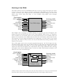
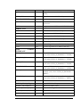
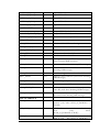
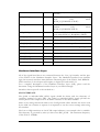
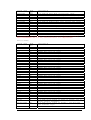
The HERON specification assigns pins on the HERON module that give a HERON
module access to the carrier ID of the carrier that it is plugged into, and a unique HERON
slot identifier.
These IDs are used by the configuration FPGA so that the module is addressed on Heron
Serial Bus (HSB) using this information. These signals are also connected to the user FPGA
so a user program can use them if required.
General Purpose LEDs
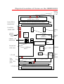
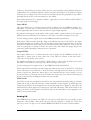
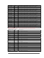
There are some LEDs on the HERON-IO2 that are connected via a buffer to some of the
FPGA I/O pins. There are five such LEDs, which can be used by the FPGA program to
indicate various states of operation.
Done LEDs
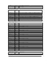
There are two Done LEDs, that are illuminated if the relevant FPGA is not configured.
LED “DONE” is connected to the User FPGA
LED “CNT DONE” is connected to the Control FPGA.
This means that the “CNT DONE” LED should flash at power on, and then go out
showing that the control FPGA is ready to accept a configuration stream for the User
FPGA.
After downloading a bitstream to the user FPGA, LED “DONE” should also go out.
Serial Ports
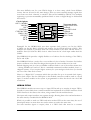
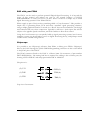
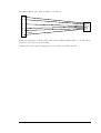
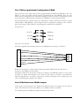
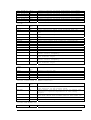
There is a connector on the HERON-IO2 that provides the opportunity to use a variety of
serial port configurations. There is a MAX3160 “protocol converter” chip provided external
to the FPGA, which can provide: 1 channel 4 wire RS232
With RTS and CTS
2 channels of 2 wire RS232
Without RTS and CTS
1 channel of 4 wire RS485
One pair in each direction
2 channels of 2 wire RS485
Two bi-directional pairs
In addition there is a Differential ECL transceiver chip provided that gives one differential
ECL input and one differential ECL output, such as is used by FPDP.
The components are purely voltage level converters, and any UART logic must be
implemented in the user FPGA.
15
HUNT ENGINEERING HERON-IO2 USER MANUAL